In-band crosstalk could be one of the main factors limiting the performance of wavelength-division-multiplexed (WDM) transport networks [1-8]. This crosstalk could be generated, for example, at imperfect optical add-drop multiplexers, or by double Rayleigh backscattering in distributed Raman amplified systems [3-8]. To estimate the scalability of such WDM transport networks, it is important to evaluate accurately the power penalty induced by in-band crosstalk. However, the impact of in-band crosstalk on the system’s performance depends on the modulation format [4-7]. For example, it has been reported that differential phase-shift keying (DPSK) signals are ~6 dB more tolerant to in-band crosstalk than on-off keying (OOK) signals [4]. However, in this comparison of two modulation formats, the effect of optical receiver configuration was not taken into account. It is well known that the in-band crosstalk-induced penalty of OOK signals can be reduced using an optimized decision threshold at an optical receiver [1]. On the other hand, there is no difference in a system’s performance between optimized and fixed threshold conditions for DPSK signals, when a balanced direct-detection receiver is used [9]. Thus, we could expect that the 6-dB difference in the in-band crosstalk tolerance of DPSK and OOK signals could be reduced by simply optimizing the decision threshold of the receiver. In this paper, we derive simple equations for the estimation of power penalties induced by in-band crosstalk for differentially phase-modulated signals (which could be received with a cost-effective direct-detection scheme), for two different optical receiver configurations: a balanced detection, and a single-ended detection. Our equations enable us to simply calculate the in-band crosstalk-induced penalties. Then, we show that the power penalties obtained by our equations agree well with experimental data.
II. IN-BAND CROSSTALK-INDUCED PENALTIES
In OOK signal transmission systems, the sensitivity penalty induced by in-band crosstalk may be estimated using the following equation:

where
However, when the decision threshold is adjusted to minimize the bit-error rate (BER) in a beat-noise-limited receiver (the decision threshold is slightly moved toward ‘0’ level, compared to the fixed case.), the power penalty induced by in-band crosstalk can be expressed as [1].

For DPSK and DQPSK signals, Eq. (1) and (2) cannot be used directly for the calculation of in-band crosstalk-induced penalties, due to the different symbol constellations from OOK signals. Thus, in order to derive simple equations for in-band crosstalk-induced penalties in those phase-modulated signals, we take into account the probability of nonzero-amplitude symbols and symbol distances of the phase-modulated signals. For OOK signals, the in-band crosstalk is generated only by the ‘1s’ of the signals. On the other hand, the crosstalk is generated by both the ‘1s’ and ‘0s’ of the signal for DPSK signals, since DPSK is a constant-amplitude modulation format. Therefore, Rc in Eq. (2) should be replaced with 2·

In the case of balanced detection, the symbol distance of a DPSK signal is twice as long as that of an OOK signal. Thus, under the same BER requirement, the amplitude of a DPSK signal in balanced detection should be halved, in comparison to single-ended detection. This implies that the effect of in-band crosstalk would be decreased to one quarter as much, since the crosstalk power is proportional to the signal amplitude squared. In addition, the optimized threshold of a DPSK receiver would be always located in the middle of the two symbols of the signal, even in a beat-noise-limited receiver. Thus the power penalty for a DPSK signal detected using a balanced receiver can be expressed as

In the case of a DQPSK signal, the crosstalk components could beat with four symbols of the signal having nonzero amplitude. Therefore, for single-ended detection,

In the case of balanced direct-detection, the intersymbol distances between four symbols of a DQPSK signal were taken into account. For one reference symbol, three intersymbol distances would be increased, compared to that of an OOK signal: twice for one, and times for the other two. Therefore, the effects of in-band crosstalk power were respectively decreased to a quarter for one and a half for the other two. By considering the average symbol distance between other symbols (i.e. inclusion of a factor of (1/4+2×1/2)/3=5/12 in Eq. (5)), the in-band crosstalk-induced penalty for a DQPSK signal could be estimated with the following equation:

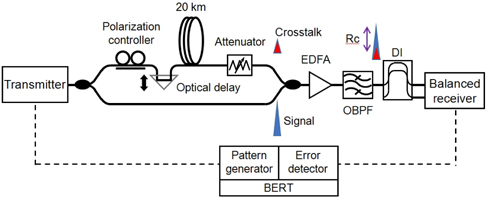
Figure 1 shows the experimental setup for measuring power penalties induced by in-band crosstalk. We first generated 10-Gbaud DPSK and DQPSK signals using external phase and IQ modulators respectively. Then the signals were split into two paths using a 10:90 optical coupler: 90% for the signal path and 10% for the crosstalk path. In the crosstalk path, a variable optical attenuator and a 20-km SSMF were used to adjust respectively the crosstalk level and the decorrelation between signal and crosstalk. We also inserted a polarization controller and a variable optical delay line into the crosstalk path, to maximize the deleterious effects of in-band crosstalk, as it is well known that the effects of in-band crosstalk on a system’s performance are sensitive to polarization and timing alignment between signal and crosstalk. Then the signal and crosstalk components were recombined with a 3-dB coupler and fed to an optically preamplified receiver (OSNR of the received signal was set to be larger than 30 dB for all measurements). The receiver was composed of an erbium-doped fiber amplifier (EDFA), an optical bandpass filter (OBPF, bandwidth = 0.17 nm), a delay interferometer (DI), and a photodetector. The free-spectral range of the DI was 10 GHz. After photodetection using either a single-ended or balanced receiver, we finally measured the BER of the signal.
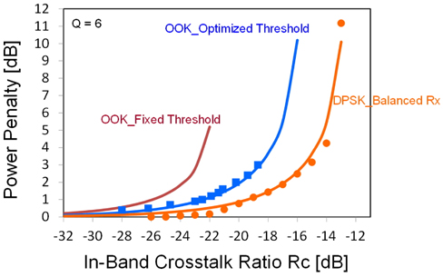
First we measured the in-band crosstalk penalty of a DPSK signal with the balanced detection scheme at a BER of 10-9 (
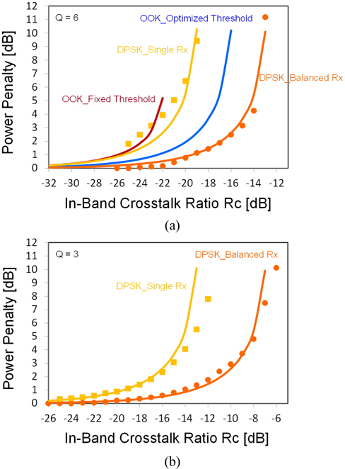
To evaluate the effect of optical receiver configuration, we also measured in-band crosstalk penalties for the DPSK signal with single-ended detection, as shown in Fig. 3. For comparison, the measured penalty for the DPSK signal with balanced detection and the four calculated penalties obtained from Eq. (1), (2), (3), and (4) were also presented in Fig. 3(a). The results show that the DPSK signal with single-ended detection was respectively 6 and 3 dB less tolerant (@ 1-dB penalty) to in-band crosstalk than the DPSK signal with balanced detection and the OOK signal with an optimized threshold of the optical receiver. Also shown in Fig. 3(a) is that the tolerance to in-band crosstalk of the DPSK signal with single-ended detection was between the OOK signals with fixed and optimized threshold schemes. Fig. 3 (b) shows the measured in-band crosstalk-induced penalties at a BER of 10-3(
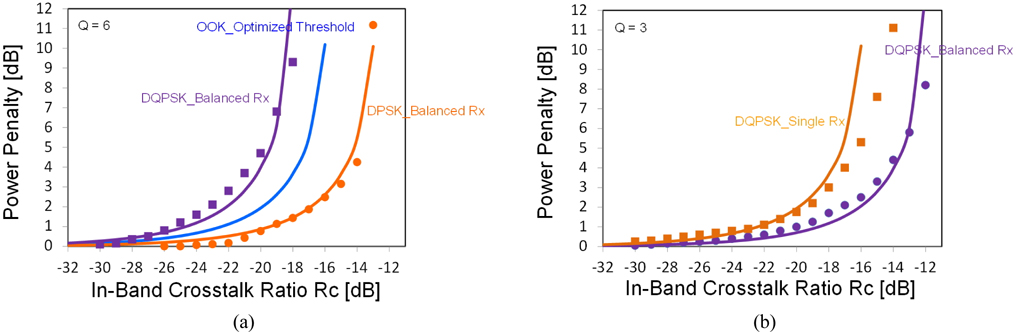
Figure 4(a) shows the measured power penalty at a BER of 10-9 (
Table 1 summarizes the tolerable (giving a 1-dB penalty at
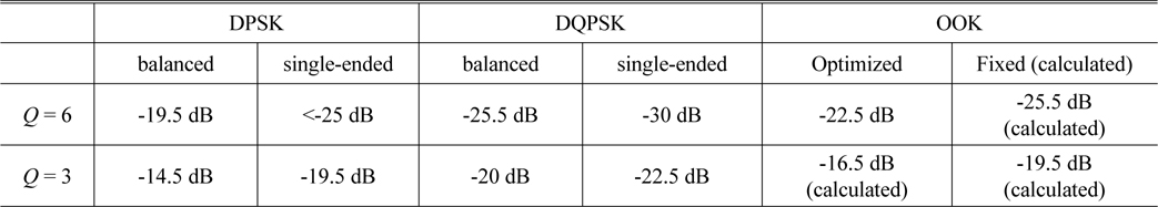
Tolerable crosstalk level for three different modulation formats, for a 1-dB sensitivity penalty guideline. Each crosstalk level was estimated from the measured penalties, except for the OOK signal with an optimized threshold at Q = 3 and with fixed threshold cases at both Q values
The in-band crosstalk-induced penalties for DPSK and DQPSK signals have been investigated for two different direct-detection schemes: balanced and single-ended. First, we have found the difference in in-band crosstalk tolerance between a DPSK signal with balanced detection and an OOK signal to be ~3 dB, as long as an optimized threshold for a beat-noise-limited receiver is used for the measurement. We have also derived simple equations to estimate the in-band crosstalk-induced penalties for DPSK and a DQPSK signals with different