The advent of the wavelength division multiplexing (WDM) technique around 1992 started a revolution in optical fiber transmission systems. In order to use the maximum transmission capacity of optical fibers and to maximize optical networks’ throughputs to their maximum possible values, designers should rely on high speed, low loss, low power consumption and compact alloptical components [1]. These components are vitally important to design and fabricate complex and efficient terminal equipment. Photonic waveguides and photonic crystal waveguides (PCW) are two competing available optical component design platforms. Integration is another technical possibility with its own advantages, compatible with the above-mentioned requirements.
One of the key WDM components is the De-multiplexer (DEMUX), which is characterized by the number and selectivity of it output channels. Some photonic waveguide based DEMUX designs are reported by researchers [1-6]. Because of their weak optical confinement, these components are not of interest of the researchers, whereas more compact designs are possible based on photonic crystal technology [7, 8]. Photonic crystal (PhC) based DEMUX designs are superior in this respect [7-11]. Various methods are proposed by researchers to provide the required frequency selectivity of the output channels. Whilst directional coupler based selectivity has been used in [12-14], resonator based selectivity has been proposed in [7, 15, 16], using cavity, line and ring resonators. Channel bandwidths of the directional coupler based designs are wider than their resonator based counterparts.
Decreasing the group velocity of light leads to enhancement of the wavematter interaction which may be used to improve performances of optical components [18-20]. Photonic crystal waveguide is a suitable medium to control the speed of light and hence is a relevant platform to design slow light based photonic devices [18-20]. In this study we consider the impact of slow light technology on the photonic crystal based DEMUX. In a design reported in 2011 a compact wavelength DEMUX using cascaded single mode PCW utilizing the slow light regime wasproposed [21]. That design is based on a near band-edge slow light operating point, resulting in a large value of group velocity dispersion (GVD).
The effects of light speed on the performance of PC DEMUXs have not yet been considered in the previous studies. This study, firstly proposes a PhC based DEMUX, consisting of a main waveguide and cavity coupled output channels under a slow light regime, secondly analyses the structure numerically to demonstrate de-multiplexing operation and finally studies the impact of light speed on the performance of the proposed structure. The remainder of the paper is organized as follows: Section II considers the structure of the proposed DEMUX, its operation principles and design considerations based on a series of relevant numerical simulations. The effects of the speed of light on performance of the proposed structure are also studied in Section II. Section III is devoted to discussion and conclusions.
II. DESIGNING A PHOTONIC CRYSTAL SLOW LIGHT BASED DEMUX
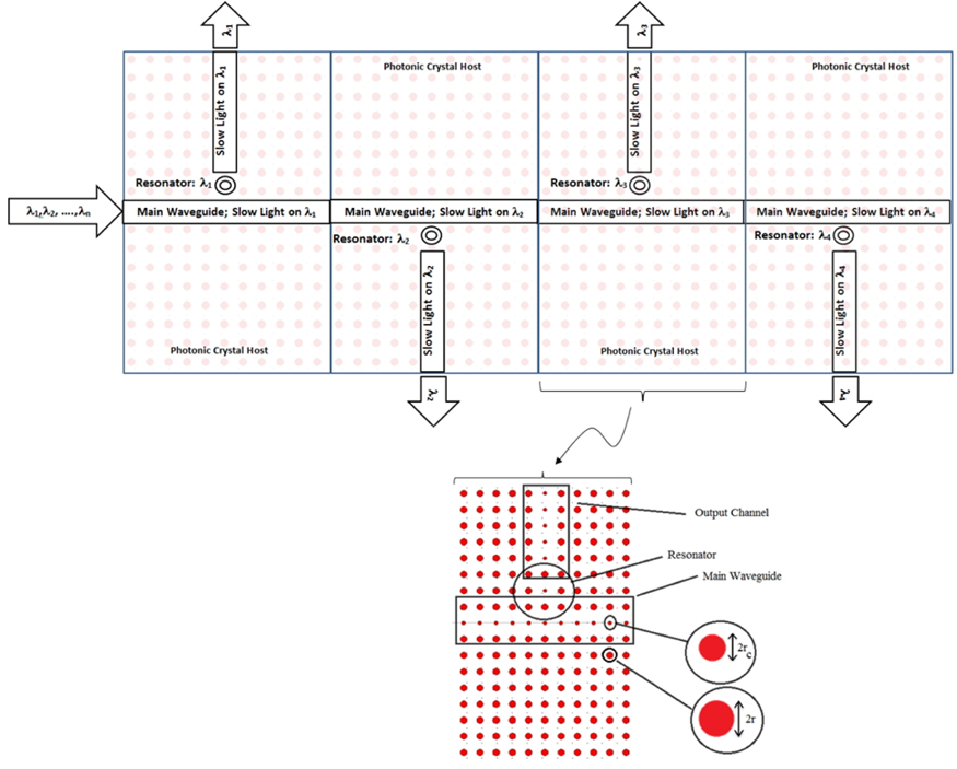
The proposed design consists of a main waveguide carrying input channels,
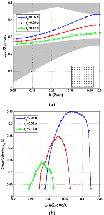
The plane wave expansion method, PWE, is the method of choice to find the dispersion diagram of PCWs, although other methods such as FDTD, FEM, …are used too. In our study we have used the PWE method and selecting an appropriate supercell using MIT photonic band (MPB) package [26] along with Bandsolve tools of Rsoft package [27]. The dispersion curve of the PCW should be located inside the bandgap of the hosting photonic crystal. The proposed photonic crystal structure exhibits a bandgap only for TM polarization. The resulting dispersion diagram for the TM mode of the main PCW of the Fig. 1 is shown in Fig. 2(a) for three values of rc. Simulation parameters are:
As it is indicated in the Fig. 2(a) the slope of the dispersion curves of the TM propagation modes depend on the radii of central rods of the PCW (
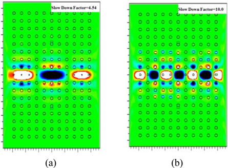
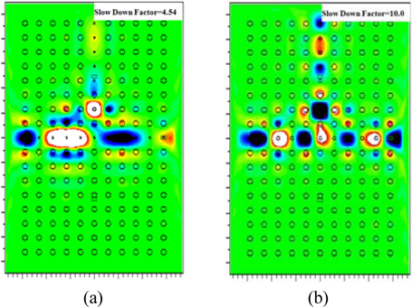
Figure 3 shows the electric field distribution of the TM propagating mode of the PCW for two different slowdown factors of
In the design under study, this integration finally will lead to an enhancement of energy transfer from the main PCW to output channels. In Fig. 4, the relation of the main PCW and one of the output channels is indicated. Selectivity of energy transfer is due to selectivity of slow light operation of the main PCW in the coupling region, inherent selectivity of the side coupled cavity and selective slow light operation of the output channel, all on the assigned output wavelength. Figure 4(a) and Fig. 4(b) repeat the field distribution of Fig. 3 with the same parameters considering one of the output channels on wavelength of
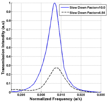
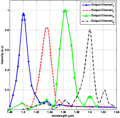
A Gaussian optical pulse, covering the whole frequencyrange-of-interest, is launched at the input of the main waveguide. Power monitors were placed at the output channel to collect the transmitted spectral power density. The transmitted spectral power densities were normalized to the incident light spectral power density from the input port. Figure 5 shows the transmission coefficient of the output channel against normalized frequency (
The same principle of operation is applied to all channels of DEMUX under study. Designing parameters of the DEMUX, using scalability of PhCs and their derived structures are indicated in Table 1.
[TABLE 1.] Designing parameters of four channels DEMUX
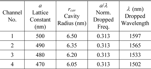
Designing parameters of four channels DEMUX
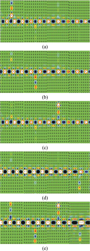
Figure 6(a) to 6e indicate electric field distributions in the DEMUX structure under separate channel excitations at λ1=1.597 µm, λ2=1.565 µm, λ3=1.533 µm, λ4=1.502 µm and under full DEMUX spectrum, λ1 to λ4, excitation.
The Fig. 7 shows normalized transmission spectrum of the DEMUX, with a good channel separation (cross talk) and correct channel placement.
This study shows capabilities of slow light to enhance the performance of photonic crystal demultiplexers. The component consists of a main photonic crystal waveguide and side coupled cavity assisted output branches. The signal in each of the de-multiplexer channels, in addition to pass through the selective element of cavity in its path, undergo selectively twice the slow light propagating condition, the first time in the coupling region of the branching point and then in the output channel waveguide. Our study indicates that each of the slow light regions enhances independently the overall frequency spectrum of the de-multiplexer, both in amplitude and channel selectivity aspects.