Small lightweight satellite has the advantages of low cost, short production cycle and flexible means of transmission, thus it has a strong demand and has developed rapidly in recent years. The main demand for the small lightweight satellite market is high resolution optical remote sensing imaging, thus carrying space optical remote sensing camera is an important application of small lightweight satellite [1-3].
Compared with space optical remote sensing cameras carried by traditional large and medium-sized satellite platform, the lightweight requirements of space optical remote sensing camera carried by small lightweight satellites (hereinafter referred to as “small lightweight space camera”) are more stringent [4]. Weight of opto-mechanical structure usually accounted for more than 80% that of the whole camera, so the lightweight design of the small lightweight space camera is mainly for opto-mechanical structure. According to the function, opto-mechanical structure of small lightweight space camera can be divided into two parts with one participating in imaging and one not participating in imaging. The former one includes the mirror assemblies and detector assemblies, etc. In order to ensure the imaging quality, material selection and lightweight extent of these components are limited, and the optimization design space is small. The latter one mainly includes the framework and light blocking covers, etc. The major function of framework is to provide the installation platform for imaging parts and to ensure that the small lightweight space camera meets the static and dynamic requirements. In general, framework which accounts for about 50% of the weight of the total opto-mechanical structure has a relatively larger selection of materials and the optimization design space is large. The lightweight design of this part can effectively reduce the weight of the small lightweight space camera. [5, 6]
Using a suitable structural material with low density is an important means of lightweight design for a space camera [7]. Carbon fiber composite (CFC), which has the advantages of low density, high specific stiffness, small linear expansion coefficient and ease of design, is an ideal material for optomechanical structure of small lightweight space camera.
At present, CFC has been widely used in the ground-based and space-based optical instruments [8-10]. Such as the HiRISE high resolution camera, where the main support structures like the main bearing force plate, truss rods, etc. are made of CFC.
In this paper, a framework for small lightweight space camera made of CFC (M40J) was designed. An integrated optimization design method and the optimization strategy which combined genetic global optimization algorithm with downhill simplex local optimization algorithm were adopted to optimize the structure parameters of the framework. Finite element analysis was used to verify the rationality of the optimization results. Finally, a mechanical test was used to prove the stability of the camera.
II. OPTICAL SYSTEM AND CFC FRAMEWORK DESIGN
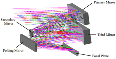
The small lightweight space camera presented here employs an F/8 off-axis Cook-TMA [11] optical system with a focal length of 875 mm working in the spectrum of 480 nm ~ 850 nm, and it consists of 4 mirrors, presented in Fig. 1. The primary mirror is a concave aspheric mirror with an effective aperture of 588 mm×142 mm whose vertex radius is 4767 mm. The secondary mirror is a convex oblate elliptical mirror with an 86 mm×86 mm effective aperture and its vertex radius is 1116 mm. And the third mirror is also a concave aspheric mirror whose effective aperture is 605 mm×174 mm and vertex radius is 1249 mm. The folding mirror with an effective aperture of 552 mm×101 mm is a plane mirror, which is located near the secondary mirror and is used to reflect the light rays and decrease the optical system volume to 605 mm×500 mm×630 mm. Without central obscuration or intermediate image, the optical system can achieve a large field of view of 34°×2°.
In general, the main factor influencing the surface tolerance of optical elements is the mirror supporting structure. Main influence factors of the optical element position tolerance are structural stiffness and thermal adaptation of framework, stiffness and alignment accuracy of mirror support structure. Therefore, in the framework design process, the impact on optical element position tolerance is the main consideration.
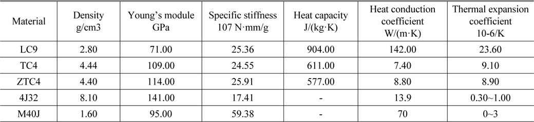
High stiffness, low expansion coefficient, good stability and good process are the target of structural materials for a space camera [12]. But in practice, finding a material that meets all the requirements mentioned above is quite difficult. Table 1 gives several typical structural materials applied in a space camera [13].
[TABLE 1.] Typical structural materials applied in space camera
Typical structural materials applied in space camera
According to the table, CFC (M40J) has the advantages of low density, high specific stiffness, etc. Simultaneously, CFC has good designability. The content and performance of carbon fibers and laying method as well as the matrix properties determine the physical properties of CFC [14]. Thus, M40J was chosen to complete the framework design. As for the metal embedded parts in each position of the CFC framework interface, TC4 was selected.
2.3. Framework Design Approach
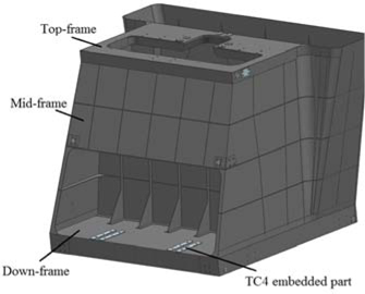
The framework was designed according to the location of each optical element in the optical system. First of all, in order to guarantee the relative position between the primary mirror and the third mirror, a relatively rigid structure, namely the Down-frame, was designed to connect them. Secondly, in order to guarantee the relative position of the secondary mirror and the folding mirror, a relatively rigid structure, namely the Top-frame, was designed. Finally, a frame with enough structure stiffness, namely the Mid-frame, was designed to connect the Top-frame and the Down-frame, and to guarantee their relative positions. The CFC Framework is shown in Fig. 2.
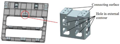
Because of the limitation of the manufacturing process, the surface accuracy of the M40J framework is quite low and if we install optical elements directly onto it, great assembling stress will be induced, thus reducing the surface accuracy of the mirrors. Furthermore, direct mechanical polishing on the framework surface is not allowed. Therefore, TC4 metal parts were embedded in each position of the framework interface, and by grinding of the embedded parts, highly precise mounting surfaces were achieved. Figure 3 shows one of the TC4 embedded parts located at the Down-frame.
III. INTEGRATED OPTIMIZATION OF CFC FRAMEWORK
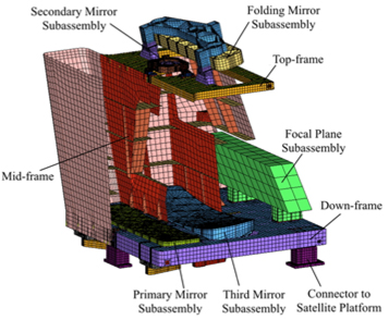
In the previous section, we completed the preliminary design of the CFC framework. The finite element (FE) model of the camera system was generated by Altair Hypermesh. In order to clearly show the inner structure, Mid-frame is displayed by half section view, presented in Fig. 4. The CFC framework, including Top-frame, Mid-frame and Down-frame, was meshed by using 2D elements, and the other parts of the camera system, including mirror subassemblies, TC4 embedded parts and connectors to satellite platform, were meshed by using 3D elements. To reduce the scale of FE model and improve the efficiency of optimization calculation, focal plan subassembly was simplified by replacing it with mass block which had the same mass, moment of inertia and stiffness. The total number of grid points in the FE model of the camera system is 233163, and the FE model consists of 124629 hexahedral elements, 6705 pentahedral elements, 20537 quadrilateral elements and 269 triangular elements. Mirrors in the camera are made of silicon carbide (SiC), whose Young’s modulus is 330 GPa and density is 3.2g/cm3. Support structures in each mirror subassembly and the connectors to satellite platform are made of TC4. From Fig. 4 we can get that the CFC framework is a typical thin-wall multi-cavity structure. Force condition differs in different positions, so the thickness of the framework in different positions should also be different.
3.1.1. Design Variable
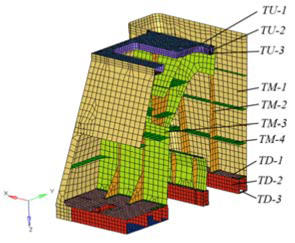
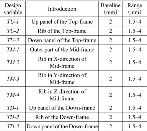
Theoretically, the more CFC framework regions of the space camera we divide, the better optimization results we will get. But considering the actual framework size, mold manufacturing difficulty, production process, computational complexity and structural characteristics, the framework was divided into 10 regions, as shown in Fig. 5. A description of each design variable is given in Table 2.
[TABLE 2.] Properties of each framework region

Properties of each framework region
3.1.2. Design Constraint
According to the design requirements, the first order frequency of a space camera using CFC framework must be greater than 100 Hz.
3.1.3. Objective Function
We take the minimum weight of the CFC framework as the optimization goal, in order to reduce the weight of the space camera.
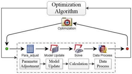
In the optimization process, there are 10 design variables, and in each optimization cycle, we should accomplish the thickness parameter updating of the 10 different regions, the framework weight statistics and the space camera modal analysis. To solve the multi-parameter optimization problem, an integrated simulation and optimization design method was established [15]. Figure 6 shows the analysis process and the corresponding software tools. Finite element analysis software Altair Hypermesh and Altair Optistruct were integrated by utilizing the integrated optimization software Isight. Through the intermediate data transmission between different software, an optimization loop was achieved which connected the thickness parameters adjustment of each region, finite element model updating, camera modal calculation, CFC framework weight statistics, and results feedback judgement. In this way, huge workload of manual adjustment and separately analysis by different software was avoided, and the structural design efficiency has been greatly improved.
3.2. Response Surface Analysis
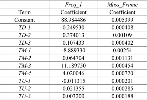
As mentioned above, the CFC framework was divided into 10 regions, thus there were 10 design variables and the design space was huge. Responses to 5000 design points of the design space, sampled by the Design of Experiments (DOE) based on Optimal Latin Hypercube Sample method, were calculated. Furthermore, the first-order polynomial approximate model of design variables on the first order frequency and CFC framework weight was obtained by Response Surface Methodology (RSM). Polynomial coefficients are shown in Table 3. The fitting error of the first order frequency is 2.6% and that of the CFC weight is 0.2%. Thus we can conclude that the approximate model has a high reliability because the fitting error is small enough.
[TABLE 3.] First Order Polynomial coefficients of RSM
First Order Polynomial coefficients of RSM
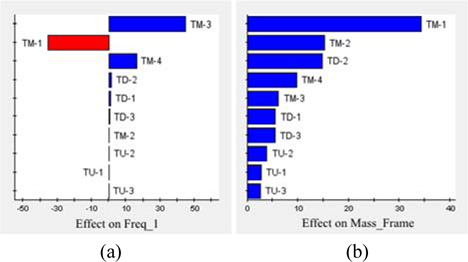
The Pareto contributions of the design variables to the first order frequency and the CFC framework weight are shown in Fig. 7. In the figure, a positive value indicates the positive effect, and a negative value indicates the negative effect. It can be seen that the Mid-frame has a relatively greater influence, especially the outer part of the Mid-frame (TM-1). Thickness of this region has the largest contribution to the weight of CFC weight, but its influence on the first order frequency is negative. Contributions of Top-frame and Down-frame to the first order frequency and the CFC framework weight are relatively small.
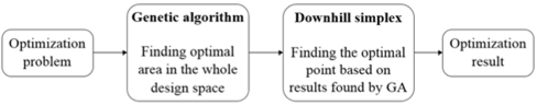
In the optimization process of each region thickness, due to the large number of design variables, if we simply employ the gradient optimization algorithm, local optimal solution instead of the global optimal solution will be obtained, and if we only employ the global optimization algorithm, computational complexity will be very large. Hence, we should use a global optimization algorithm to find the optimal region in the whole design space first, and then use the gradient optimization algorithm to find the optimal solution.
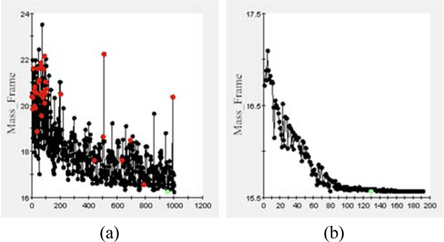
The optimization strategy presented in this paper combined the Genetic Algorithm (GA) with Downhill Simplex (DS) algorithm. Firstly, employing GA to find optimal area in the whole design space, and then employing DS to find the optimal point based on results found by GA. Figure 8 shows the block diagram of optimization strategy.
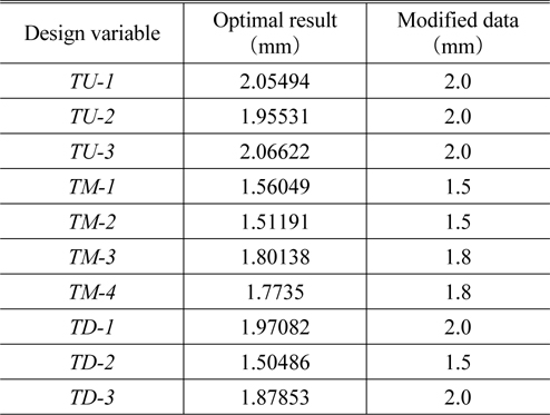
Optimization results were obtained by using the optimization strategy mentioned above. Figure 9 shows the iteration process of optimization. Table 4 gives the optimization results. A rounding operation was added to the optimal point. After optimization, the total weight of the CFC framework and the TC4 embedded parts is 15.6 kg, accounts for only 18.4% that of the camera.
[TABLE 4.] Optimization result

Optimization result
IV. NUMERICAL ANALYSIS AND EXPERIMENT
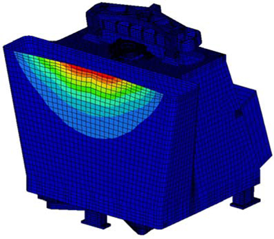
Structural stiffness of the CFC framework was analyzed to verify the optimization results of each region’s thickness by using a finite element method. According to the optimal point, the FE model of the small lightweight space camera was made. Through finite element analysis, the first order frequency of the camera reaches 104.8 Hz and the corresponding mode shape is shown in Fig. 10. From the result we can get that the structural stiffness of the CFC framework after optimization is high enough to meet the requirements of the small lightweight space camera.
4.2. Experimental Verification
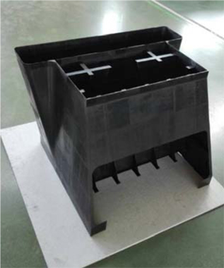
According to the optimization result, CFC framework was made after taking the manufacturing process into consideration. Figure 11 shows the Mid-frame made of M40J.
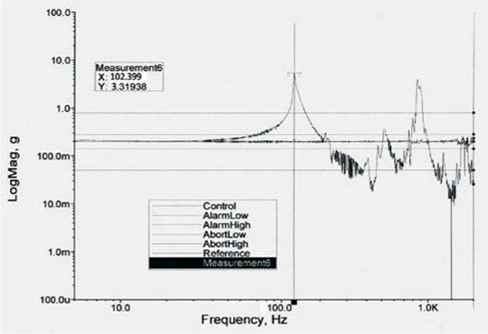
A mechanical environment test of the small lightweight space camera was performed after alignment was completed. Figure 11 shows the response curve of a sweep frequency vibration test. It’s shown that the first frequency of the camera reaches 102 Hz, which is consistent with the simulation result. It further verifies the rationality and correctness of the optimization result.
By taking the spatial layout characteristics of each optical element in the optical system into consideration, a framework for small lightweight space camera made of M40J was designed. Integrated optimization design method and the optimization strategy combined genetic global optimization algorithm with downhill simplex local optimization algorithm were adopted to optimize the structure parameters of the framework. Meanwhile, TC4 embedded parts were used to solve the low accuracy of the CFC framework interface problem. By optimizing, the total weight of the CFC framework and the TC4 embedded parts is 15.6 kg, accounting for only 18.4% that of the camera. The first order frequency of the camera calculated by finite element analysis reaches 104.8 Hz, which meets with that of the experimental test result, 102 Hz.
The CFC framework designed in this paper effectively solves the problem that the contradictory pursuit of light weight and high structural stiffness for small lightweight space camera. The launch costs have been reduced by minimizing the weight of the framework and taking the stability of the space camera into account at the same time. The integrated optimization method and the combined optimization strategy presented here can be used for future applied optics projects, which can greatly improve the design efficiency.