검색 전체 메뉴
PDF
맨 위로
OA 학술지
Design and Simulation of Two-Dimensional OCDMA En/Decoder Composed of Double Ring Add/Drop Filters and Delay Waveguides
  • 비영리 CC BY-NC
  • 비영리 CC BY-NC
ABSTRACT
Design and Simulation of Two-Dimensional OCDMA En/Decoder Composed of Double Ring Add/Drop Filters and Delay Waveguides
KEYWORD
Ring resonator , Optical code division multiple access , Transfer matrix method
  • I. INTRODUCTION

    Optical code-division multiple access (OCDMA) is one of the solutions for flexible high-capacity access network systems. The OCDMA network system provides several advantages as follows. The coding operations are performed all-optically, resulting in all optical processing thus low access delay. It can be operated in a fully asynchronous manner which makes the network system quite simple. The network capacity can also be simply varied on demand by easily adding or removing the users. The quality of service (QoS) can be easily controlled by assigning different codes indicating an appropriate QoS to users. The OCDMA can also provide passive code decryption, and protection of the optical physical layer to cope with the increasing demand in security and privacy in parallel with tremendous growth of information transfer volume [1, 2].

    The OCDMA techniques are called incoherent or coherent OCDMA depending on whether their coding is based on optical power or on optical field. The OCDMA can also be implemented in one dimension (1-D) which is only time domain or only frequency domain with phase coding, or in two dimensions (2-D) which are a combination of wavelength hopping coding and spectral phase coding. Incoherent time-spreading 1-D OCDMA has drawn wide attention due to its simple implementation. Nevertheless, incoherent OCDMA systems exhibit drawbacks such as limited code size, low bandwidth efficiency, and relatively poor auto- and cross-correlation characteristics [3-5]. The relatively poor characteristics of the incoherent 1-D OCDMA networks can be improved in 2-D incoherent OCDMA systems in which the coding operation is performed both in temporal and spectral domains [6-8]. Further improvement of the characteristics in terms of correlation property, frequency efficiency, capacity, security, and dispersion can be obtained in 2-D coherent OCDMA systems.

    For the realization of coherent OCDMA, superstructure fiber Bragg grating (SSFBG) has been used due to its high performance, compactness, compatibility with fiber-optic systems, and potentially low cost [9, 10]. Although the spectral phase code (SPC) can be reconfigured in the 2-D coherent OCDMA system based on SSFBG, the temporal code is fixed by the grating pattern of SSFBG array. Therefore, its flexibility and the number of available codes are limited. Also practically, it is quite difficult to fabricate long FBG array (consisting of FBGs with different central wavelengths) with wavelength order precision.

    On the other hand, en/decoders based on optical micro-ring resonators can provide rapid reconfiguration of temporal wavelength hopping code (WHC) as well as spectral phase code (SPC). An optical en/decoder based on micro-ring resonators for spectral phase en/decoding has been demonstrated, which is very compact, rapidly reconfigurable, and with high frequency resolution and accurate phase control [11]. 2-D coherent OCDMA en/decoders have been proposed in the form of coupled-ring reflector filters, triple-ring add/drop filters combined with delay waveguides [12, 13]. In this paper, we propose an integrated optical en/decoder based on double-ring add/drop filters (ADFs) combined with delay waveguides. The concept of the en/decoder is essentially the same as the previously reported ones, but the yield in the production of the coupled-ring reflector filters, the triple-ring, and/or quadruple-ring add/drop filters is likely to be worse than that in the production of double-ring add/drop filters. Obviously the triple- and quadruple-ring add/drop filters provide better response in terms of flat top characteristics than the double-ring one. But, the uniformity of the triple- and quadruple-ring add/drop filters in the en/decoders should be much tighter than that of double-ring ADFs. Therefore, the double-ring ADFs seem to be preferable if the performance of the 2-D coherent en/decoder composed of double-ring ADFs is comparable to that composed of triple-ring ADFs. The en/decoder discussed in this paper is very flexible to generate and recognize the 2-D coherent optical code and can simultaneously reconfigure WHC and SPC patterns using a single device.

    In Section II, the configuration of the 2-D coherent en/decoder is presented and its analysis approach is discussed. In Section III, the decoder output waveforms are assessed for various decoder codes and the worst auto-correlation peak level over the maximum cross-correlation level (P/C) is evaluated at the center of the correctly decoded pulse. Finally the conclusions are given.

    II. CONFIGURATION OF OCDMA EN/DECODER AND SIMULATION METHOD

    The configuration of an OCDMA en/decoder is shown in Fig. 1. A short pulse from a multi-wavelength source is launched and each pulse belonging to a certain wavelength can be dropped from an appropriate double-ring ADF depending on the target wavelength hopping code corresponding to the desired OCDMA code. The phase of each pulse of certain wavelength can also be tuned according to the desired 2-D OCDMA code using the tuning electrodes on top of the delay waveguides. In other words, the pulses belonging to each wavelength can be shuffled in the time space with a proper phase coding, which means that this device can be used as a two-dimensional OCDMA (Optical Code Division Multiple Access) encoder/decoder [12, 13].

    A double-ring ADF shown in Fig. 2 is considered to illustrate the transfer matrix method [14]. In this method, the transfer matrix through i-th coupler relating the input and output waves of two waveguides is given by

    image

    where κi and ti are the cross-coupling and the pass-through ratios of the i-th coupler, respectively, and . The phase between the couplers in the ring i can be accommodated through the phase matrix

    image

    Then, the pass-through (T) and drop (D) responses through the whole add/drop filter are given by

    image

    where Aij are the elements of the matrix

    image

    The pass-through and drop characteristics are calculated as a function of wavelength and the spectral response is multiplied with the Fourier components of the input pulse and its inverse Fourier transform is calculated to find the drop or pass-through response in the time domain. The calculation procedure for the whole en/decoder shown in Fig. 1 is in detail as follows. First the drop (D1(f )) and pass-through (T1(f )) characteristics from the leftmost ADF as a function of frequency are calculated using the transfer matrix method. Then the input to the second ADF at the upper and lower bus are given by

    image
    image

    where I(f) is an input pulse in frequency domain and τ is the delay time due to the delay waveguides in the lower bus. The output from the second ADF at the upper and lower bus are given by

    image
    image

    where D2(f) and T2(f) are the drop and pass-through characteristics from the second ADF. Similar calculations are continued until the outputs from the rightmost ADF are calculated.

    III. SIMULATION RESULTS FOR 2-D EN/DECODER

    The waveguide considered for the 2-D en/decoder is assumed to be composed of Hydex, a low-loss high-index-contrast glass-based material system [15]. The waveguide-core refractive index is 1.70, while that of the cladding is 1.45, giving a refractive index-contrast ratio of 17% with respect to the cladding. The ring and bus waveguide cores have cross sections of 1.5 μm × 1.5 μm. The perimeter of the ring is set to be 300 μm and the effective refractive index and group effective refractive index of the waveguide are 1.4277 and 1.7391, respectively. For this ring, the FSR (Free Spectral Range) is calculated to be 575 GHz and the round-the-ring trip delay along the ring is 1.74 ps. The bus-ring and ring-ring coupling ratios are 0.23 and 0.02645, respectively [16]. The waveguide loss is 0.2 dB/cm and the delay time through a delay waveguide is 200 ps. A set of four wavelengths {λ1, λ2, λ3, λ4} = {1550 nm, 1550.08 nm, 1550.16 nm, 1550.24 nm} is used for the wavelength hopping code (WHC). The spectral phase code (SPC) is encoded by adjusting the phase shifters. The wavelength response from the drop port of the ADF is shown in Fig. 3. The ADF is assumed to be tuned to the wavelengths of 1550 nm, 1550.08 nm, 1550.16 nm, 1550.24 nm. In order to assess the 2-D en/decoder performances, an input pulse is composed of four wavelengths whose full width at half maximum is 100 ps. When the WHC is {4, 3, 2, 1} and the SPC is {1, 1, 1, 1}, the encoded waveform and the associated spectrum calculated using the procedure explained in Section II are shown in Fig. 4 and Fig. 5, respectively. In Fig. 4, the pulses corresponding to λ4, λ3, λ2, and λ1 appear in sequence corresponding to the delay time of 200 ps. The decoder output waveforms for 24 different decoder WHC codes with fixed SPC of {1, 1, 1, 1} are calculated and shown in Fig. 6. The decoder output waveforms for 7 codes are indicated while the waveforms for other codes are plotted without notation. When the conjugate code, WHC = {1, 2, 3, 4} and SPC = {1, 1, 1, 1}, is used for decoding, the original optical pulse is found to be recovered faithfully. But, when the incorrect codes are used for decoding, the decoder output waveforms are spread out in the time space. At the center of the correctly decoded pulse, the auto-correlation peak level over the maximum cross-correlation level (P/C), which approximately corresponds to the Q-factor [17], is about 3.2. Even though the P/C values beyond the center of the auto-correlated pulse tends to be larger than 3.2, the P/C value at the pulse center is the most important when the decision is carried out with good synchronization procedure. For this value of Q-factor, the bit error rate could be about 10-3 which corresponds to forward error correction (FEC) limit [18].

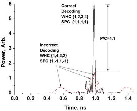
    The decoder output waveforms for 24 different decoder WHC codes with fixed SPC of {1, -1, 1, -1} are also calculated and shown in Fig. 7 together with the output waveform decoded using the correct conjugate code. At the center of the correctly decoded pulse, the worst P/C is about 4, which results in the bit error rate above FEC limit. The decoder output waveforms for 8 different decoder SPC coder with fixed WHC of {1, 2, 3, 4} are calculated and shown in Fig. 8. At the center of the correctly decoded pulse, the worst P/C is about 3.8, which is also above FEC limit. From these discussions, it is seen that the 2-D en/decoder presented in this paper can be potentially employed in the future coherent OCDMA networks when FEC technology is adopted in the network system.

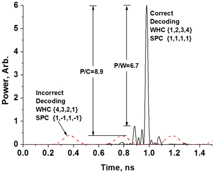
    The decoder output waveforms for most of the decoding codes are superimposed in Fig. 6 through Fig. 8 to show the overall performance and they appear quite complicated. For the comparison of the decoding performance with the results shown in [13], the correctly decoded waveform and the incorrectly decoded waveform using the worst code is shown in Fig. 9. In this case, the ratio of auto-correlation peak level over the maximum wing level (P/W) and the maximum cross-correlation level (P/C) are 6.7 and 8.9, which are better than those shown in [13]. Another incorrectly decoded waveform which exhibits cross-correlation peak at the center of the pulse is illustrated as an example of cross-correlation waveforms in Fig. 10. The simulation results illustrate that the designed OCDMA en/decoder could be slightly better than that composed of triple-ring ADF’s presented in [13] while its fabrication yield and wafer consumption could be improved in principle.

    IV. CONCLUSIONS

    A 2-D en/decoder composed of four double-ring add/drop filters and three delay waveguides is presented and its characteristics are analyzed. The drop and pass-through characteristics as a function of wavelength (frequency) are obtained using a transfer matrix method. The Fourier components of an input pulse is calculated using fast Fourier transform and the drop and pass-through characteristics of each Fourier component are calculated. Then, an inverse Fourier transform is performed whenever a time-domain waveform is required. Through these procedures, the decoder output waveforms for various OCDMA codes are found and the en/decoder characteristics are assessed. When 24 different WHC codes with a correct SPC code are used, the worst auto-correlation peak level over the maximum cross-correlation level (P/C) is 3.2 at the center of the correctly decoded pulse. When 24 different WHC codes with an incorrect SPC code are used, the worst P/C is about 4. When 8 different SPC codes with a correct WHC code are used, the worst P/C is about 3.8. In any cases, the corresponding bit error rate is smaller than 10-3, which assures error-free transmission when the FEC scheme is accomplished.

참고문헌
  • 1. Wang Z., Fok M. P., Pruncnal R. (2012) “Physical encoding in optical layer security,” [J. Cyber Security and Mobility] Vol.1 P.83-100 google
  • 2. Heratage J. P., Weiner A. M. (2007) “Advances in spectral optical code division multiple access,” [IEEE J. Quantum. Electron.] Vol.13 P.1351-1369 google cross ref
  • 3. Salihi J. A. (1989) “Code division multiple-access technique in optical fiber networks, Part I: Fundamental principles,” [IEEE Trans. Commun.] Vol.37 P.824-842 google cross ref
  • 4. Marhic M. E. (1992) “Trends in optical CDMA,” [Proc. SPIE] Vol.1787 P.80-98 google
  • 5. Sampson D. D., Pendock G. J., Griffin R. A. (1997) “Photonic code-division multiple-access communications,” [Fiber Integr. Opt.] Vol.16 P.126-157 google
  • 6. Tancevski L., Andovovic I. (1994) “Wavelength hopping/time spreading code division multiple access systems,” [Electron. Lett.] Vol.30 P.1388-1390 google cross ref
  • 7. Tancevski L., Andonovic I. (1996) “Hybrid wavelength hopping/time spreading schemes for use in massive optical networks with increased security,” [IEEE J. Lightwave Technol.] Vol.14 P.2636-2646 google cross ref
  • 8. Wang X., Chan K. T. (2003) “A sequentially self-seeded Fabry-Perot laser for two-dimensional encoding/decoding of optical pulses,” [IEEE J. Quantum Electron.] Vol.39 P.83-90 google cross ref
  • 9. Teh P. C., Petropoulos P., Ibsen M., Richardson D. J. (2001) “A comparative study of the performance of seven- and 63-chip optical code-division multiple-access encoders and decoders based on superstructured fiber Bragg gratings,” [IEEE J. Lightwave Technol.] Vol.9 P.1352-1365 google
  • 10. Teh P. C., Ibsen M., Fu L. B., Lee J. H., Yusoff Z., Richardson D. J. 2002 “A 16-chnnel OCDMA system (4 OCDM 4 WDM) based on 16-chip, 20 Gchip/s superstructure fiber Bragg gratings and DFB fiber laser transmitters,” [Proc. Optical Fiber Communication Conference (OFC’2002)] P.600-601 google
  • 11. Agarwal A., Toliver P., Menendez R., Etemad S., Jackel J., Young J., Banwell T., Little B. E., Chu S. T., Chen W., Chen W., Hryniewicz J., Johnson F., Gill D., King O., Davidson R., Donovan K., Delfyett P. J. (2006) “Fully programmable ring-resonator-based integrated photonic circuit for phase coherent applications,” [IEEE J. Lightwave Technol.] Vol.24 P.77-87 google cross ref
  • 12. Wang I. X., Gao Z. (2011) “Novel reconfigurable two-dimensional coherent optical en/decoder based on coupled micro-ring reflector,” [IEEE Photon. Technol. Lett.] Vol.23 P.591-593 google cross ref
  • 13. Ji Z., Jia D., Nie P., Zhang H., Zhang D., Zhang Y. (2015) “Two-dimensional coherent optical en/decoder using parallel-cascaded coupled third-order microring resonator,” [Opt. Commun.] Vol.347 P.123-129 google cross ref
  • 14. Poon J. K. S., Scheuer J., Mookherjea S., Paloczi G. T., Huang Y., Yariv A. (2004) “Matrix analysis of microring coupled-resonator optical waveguides,” [Opt. Express] Vol.12 P.90-103 google cross ref
  • 15. Daldosso N., Melchiorri M., Riboli F., Girardini M., Pucker G., Crivellari M., Bellutti P., Lui A., Pavesi L. (2004) “Comparison among various Si3N4 waveguide geometries grown within a CMOS fabrication pilot line,” [IEEE J. Lightwave Technol.] Vol.22 P.1734-1740 google cross ref
  • 16. Little B. E., Chu S. T., Haus H. A., Foresi J., Laine J. P. (1997) “Microring resonator channel dropping filters,” [IEEE J. Lightwave Technol.] Vol.15 P.998-1005 google cross ref
  • 17. Agrawal G. P. 2012 Fiber-Optic Communication Systems google
  • 18. Chang F., Onohara K., Mizuochi T. (2010) “Forward error correction for 100 G transport networks,” [IEEE Communications Magazine] Vol.48 P.S48-S55 google cross ref
OAK XML 통계
이미지 / 테이블
  • [ FIG. 1. ]  A configuration of a 2-D OCDMA en/decoder composed of four cascaded double-ring add/drop filters and three delay waveguides.
    A configuration of a 2-D OCDMA en/decoder composed of four cascaded double-ring add/drop filters and three delay waveguides.
  • [ ] 
  • [ ] 
  • [ FIG. 2. ]  A double-ring add/drop filter to illustrate the transfer matrix method.
    A double-ring add/drop filter to illustrate the transfer matrix method.
  • [ ] 
  • [ ] 
  • [ ] 
  • [ ] 
  • [ ] 
  • [ ] 
  • [ FIG. 3. ]  Drop characteristics as a function of wavelength for four different tuning conditions. The tuned wavelengths are 1550 nm, 1550.08 nm, 1550.16 nm, and 1550.24 nm.
    Drop characteristics as a function of wavelength for four different tuning conditions. The tuned wavelengths are 1550 nm, 1550.08 nm, 1550.16 nm, and 1550.24 nm.
  • [ FIG. 4. ]  An encoded waveform corresponding to a particular code.
    An encoded waveform corresponding to a particular code.
  • [ FIG. 5. ]  A power spectrum corresponding to the encoded waveform shown in Fig. 4.
    A power spectrum corresponding to the encoded waveform shown in Fig. 4.
  • [ FIG. 6. ]  Decoder output waveforms for 24 different decoder WHC codes with fixed SPC of {1, 1, 1, 1}. Decoder output waveforms for 7 codes are indicated while the waveforms for other codes are plotted without notation.
    Decoder output waveforms for 24 different decoder WHC codes with fixed SPC of {1, 1, 1, 1}. Decoder output waveforms for 7 codes are indicated while the waveforms for other codes are plotted without notation.
  • [ FIG. 7. ]  Decoder output waveforms for 24 different decoder WHC codes with fixed SPC of {1, -1, 1, -1}. Decoder output waveforms for 5 codes are indicated while the waveforms for other codes are plotted without notation.
    Decoder output waveforms for 24 different decoder WHC codes with fixed SPC of {1, -1, 1, -1}. Decoder output waveforms for 5 codes are indicated while the waveforms for other codes are plotted without notation.
  • [ FIG. 8. ]  Decoder output waveforms for 8 different decoder SPC codes with fixed WHC of {1, 2, 3, 4}. Decoder output waveforms for 5 codes are indicated while the waveforms for other codes are plotted without notation.
    Decoder output waveforms for 8 different decoder SPC codes with fixed WHC of {1, 2, 3, 4}. Decoder output waveforms for 5 codes are indicated while the waveforms for other codes are plotted without notation.
  • [ FIG. 9. ]  A correctly decoded waveform and an incorrectly decoded waveform.
    A correctly decoded waveform and an incorrectly decoded waveform.
  • [ FIG. 10. ]  A correctly decoded waveform and an incorrectly decoded waveform which has cross-correaltion peak at the center of the pulse.
    A correctly decoded waveform and an incorrectly decoded waveform which has cross-correaltion peak at the center of the pulse.
(우)06579 서울시 서초구 반포대로 201(반포동)
Tel. 02-537-6389 | Fax. 02-590-0571 | 문의 : oak2014@korea.kr
Copyright(c) National Library of Korea. All rights reserved.