검색 전체 메뉴
PDF
맨 위로
OA 학술지
Three-Dimensional Automatic Target Recognition System Based on Optical Integral Imaging Reconstruction
  • 비영리 CC BY-NC
  • 비영리 CC BY-NC
ABSTRACT
Three-Dimensional Automatic Target Recognition System Based on Optical Integral Imaging Reconstruction
KEYWORD
Integral imaging , Nonlinear correlation , Three-dimensional automatic target recognition
  • I. INTRODUCTION

    Object recognition’s many applications include its use in autonomous vehicles, artificial intelligence, and defense. Within this field, three-dimensional (3-D) automatic target recognition using integral imaging techniques has been an important topic of research [1-9].

    Integral imaging, first proposed by G. Lippmann in 1908 [10], employees lenslet or camera arrays to capture and display 3-D images. Each lenslet provides a different perspective on the subject, generating an elemental image for capture. The resulting array of 2-D images, illuminated from behind and projected through another lenslet array, displays a 3-D reconstruction. The technique provides full parallax, continuous viewing points, and relatively high depth resolution without the need for special glasses [10-15], all desirable characteristics.

    The mechanism for image reconstruction, itself, can be used to implement forms of auto target recognition. For example, in [4], the authors propose a method for locating the position of target objects in 3-D space. They use the fact that computational integral imaging reconstruction (CIIR) can output a range of 3-D reconstructions, each at a different reconstruction depth [14]. Then, computers apply advanced correlation filters to the range of reconstructed images created by CIIR and complete the automatic target recognition task.

    In practice, such methods are difficult to apply in real-time applications. The computation time and resources required for 3-D reconstruction limit its usefulness [6]. To address the limitation imposed by the computational cost of 3-D reconstruction, an all-optical structure for 3-D automatic target recognition offers an alternative.

    This paper proposes such an all-optical integral imaging approach. In our method, we optically reconstruct 3-D reference and target images. We then perform automatic target recognition, applying a nonlinear correlation filter to the reference and target images. To assess this proposed method, we discuss optical experiments performed and present recognition results obtained in these experiments.

    II. REVIEW OF CIIR-TYPE 3-D OBJECT CORRELATION METHOD

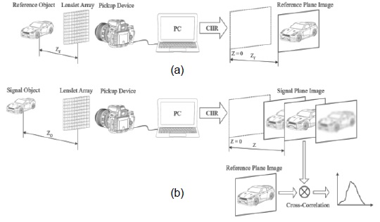
    Fig. 1 illustrates the principle of the conventional CIIR-type 3-D object correlation method. The process is separated into two main stages: pickup and recognition. In the pickup stage, we assume that zr, the distance between the reference object and the lenslet array, is known, and that the distance between the target and the lenslet array, zo, is unknown or arbitrary. For both reference and target objects, elemental images created by the lenslet array are recorded by the pickup device. In the recognition stage, a CIIR technique reconstructs images of the reference object at known reconstruction depths and the image of the target object at a range of reconstruction depths [5-9]. CIIR can be implemented by computational simulation of ray optics.

    Fig. 1(a) depicts the reference object method, and Fig. 1(b) the steps in the target object method. Fig. 1(b) also depicts the automatic target recognition step, implemented using cross-correlation between a single, reference 3-D image and the various target 3-D images.

    When recognition is implemented with this method, a high correlation peak can be obtained only at z = zr. Thus, this method can extract the depth information of a reconstructed target image that matches the depth of the reconstructed reference image.

    While the method works, CIIR is very slow, computationally, and requires substantial computing resources. Therefore, if real-time processing is required, an alternative method may be superior.

    III. PROPOSED 3-D CORRELATION METHOD BASED ON OPTICAL INTEGRAL IMAGING RECONSTRUCTION

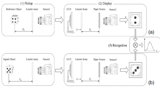
    Fig. 2 illustrates our proposed 3-D object correlation method. In the conventional CIIR-type 3-D object correlation method presented above, 3-D images are reconstructed by computer simulation. In our proposed method, an optical display system reconstructs the 3-D images. The all-optical structure allows us to implement automatic target recognition in real-time.

    Our system has three main parts: pickup, display, and recognition. For pickup, let us assume that the reference object has known position r(xr, yr, zr) at a distance of zr from the lenslet array and that the target object at t(xo, yo, zo) stands at an unknown (or arbitrary) distance, zo, from the lenslet array. Elemental images for reference and target objects are obtained by the first image sensor (Sensor 1) by way of the lenslet array.

    In the display part of the process, 3-D image reconstructtion begins when these elemental images are reproduced on a liquid crystal display (LCD). Light illuminating the LCD passes through the lenslet array, generating a 3-D optical image for capture by the second image sensor (Sensor 2) at the speed of light. This design choice produces a system that is much faster than those used to implement the conventional CIIR-type correlation method. The 3-D, optically-created images have relatively high 3-D resolution (lateral and depth) since all elemental images are superimposed by optical magnification.

    For the reference object, Sensor 2 records its reconstructed 3-D image at the known distance zr. By locating this sensor at the focal plane, we can obtain a high-quality image. We call the reconstructed 3-D image of the reference object at known zr-plane R(xr, yr, zr). This image is stored in the computer for use as a reference image.

    To record the reconstructed image of the target object, Sensor 2 is positioned at zr, the identical position from which the reference object was recorded, as shown in Fig. 2(a). Recall that, in the pickup stage, the target object was located at the zo-plane. Images reconstructed at the other various reconstruction depths are noticeably out-of-focus or blurred. Only when zo = zr is the best, clearly reconstructed 3-D image obtained. This is a main feature of our 3-D object correlation method. Let T(xo, yo, zr) be the reconstructed 3-D image of the target object as captured by Sensor 2 at zr.

    Recognition proceeds by means of a correlation process comparing T(xo, yo, zr) and R(xr, yr, zr) , the 3-D target and reference images reconstructed at a distance of zr from the lenslet array. Correlation results are obtained by means of the following kth-law nonlinear correlation filter

    image

    where are the Fourier transform and phase of the reconstructed reference image, R, at the distance zr, are the Fourier transform and phase of the reconstructed target image, T, at the distance zr, and k is the nonlinearity parameter for the correlation filter. When k = 0, Eq. (1) becomes a phase-only filter (POF). When k = 1, Eq. (1) becomes a linear correlation filter.

    IV. EXPERIMENTAL RESULTS

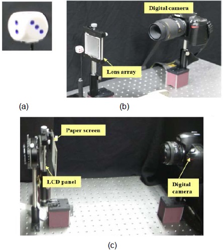
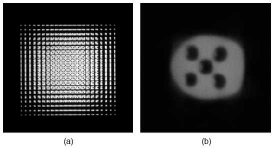
    We carried out optical experiments to assess our proposed 3-D object recognition method. A ‘die’, shown in Fig. 3(a), was used as the reference and target object in this experiment. Its size was 2 cm × 2 cm × 2 cm (W × H × D). When serving as the reference object, the ‘die’ was positioned at (xr, yr, zr) = (0 cm, 0 cm, 6 cm). The experimental setup is depicted in Fig. 3(b). Here, we used a 30 × 30 array of lenslets. Each lenslet measured 1.08 mm × 1.08 mm and was square in shape. The lenslet focal length was 3 mm. Total resolution of the elemental images was 900 × 900 pixels (H × V). Each elemental image had 30 × 30 pixels as the pixel pitch of the LCD panel shown in Fig. 3(c) was 36 μm.

    A set of recorded elemental images is shown in Fig. 4(a). We used a paper screen and a digital camera to form Sensor 2. The paper screen was placed z = 6 cm from the lenslet array. The digital camera captured images from the paper screen. An example of the images captured in this manner is shown in Fig. 4(b). This reconstructed 3-D reference image was taken at z = 6 cm.

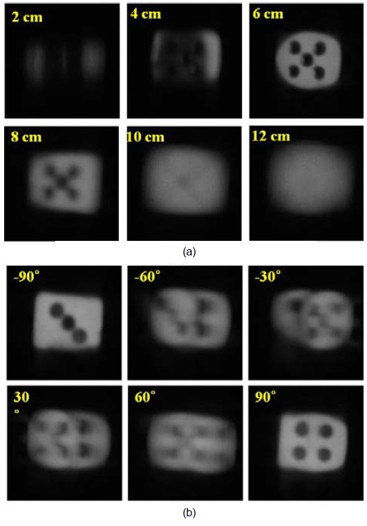
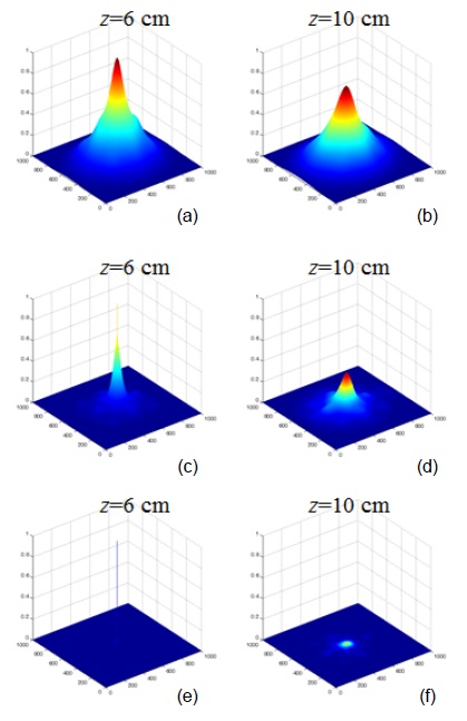
    When used as a target object, the ‘die’ was shifted along the z-axis or rotated by an arbitrary angle on the y-axis. Elemental images for each case were recorded using the optical pickup apparatus shown in Fig. 3(b). Then, with a set of elemental images for each case, reconstructed 3-D images at various reconstruction depths could be obtained using the optical display system shown in Fig. 3(c). Examples of reconstructed 3-D images at different reconstruction depths are shown in Fig. 5(a). The figure clearly shows that the 3-D image reconstructed at z = 6 cm exhibits the sharpest focus. Fig. 5(b) provides examples of the impact of target rotation angle on the reconstructed 3-D image. The figures demonstrate that reconstructed 3-D images of target objects depend on object distance and rotation angle.

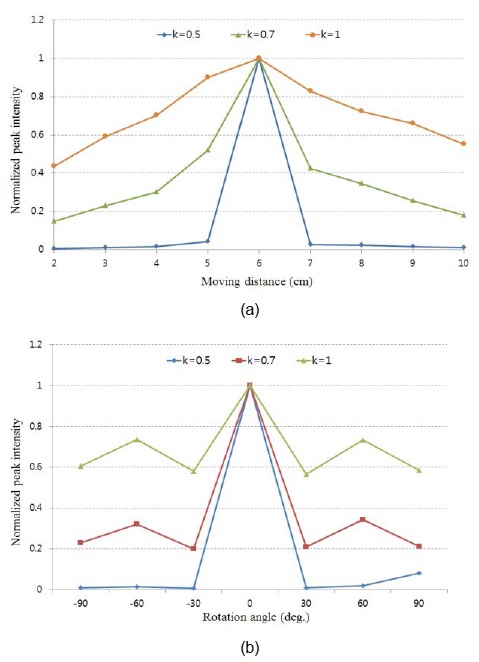
    Finally, we present the cross-correlation between the reference image and the reconstructed 3-D images of the target object at various depths and rotation angles. We computed correlation using the kth-law nonlinear correlation filter described by Eq. (1). Correlation results, with k = 0.5, k = 0.7, and k = 1, are shown in Fig. 6. The highest peaks (Fig. 6(a), (c), and (e)) correspond to z = 6 cm. In this case, the reconstruction plane matches the z-plane in which the target object was located in the pickup phase. Lower peaks were observed when the reconstruction plane and the z-plane during pickup did not match. Fig. 6(b), (d), and (f) display correlation results for z = 10 cm.

    We repeated the analysis for the other reconstructions of the target object image shown in Fig. 5. Applying the correlation test to the reference and each reconstructed target image produced the results shown in Fig. 7. Thus, we conclude that our proposed method is robust when the reconstruction plane shifts along the z-axis and when the target object is rotated.

    V. CONCLUSIONS

    In this paper, we presented a 3-D automatic target recognition system based on integral imaging and using an all-optical structure to provide real-time processing.

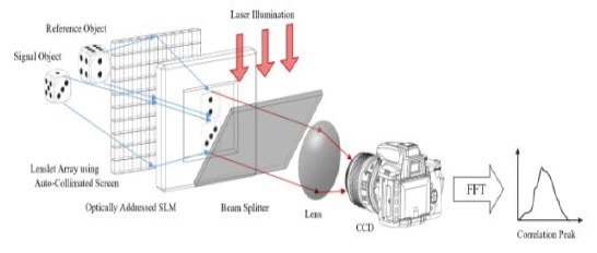
    Fig. 8 shows a practical application of our method. The two main processing stages in Fig. 2 may be combined into one imaging system using an auto-collimating screen [16]. In this system, the reconstructed 3-D images are generated at light speed and displayed on a spatial light modulator (SLM) to convert these images into coherent images. Then, a joint transform correlator (JTC) could serve as a correlation filter. This design may produce a real-time, compact 3-D object recognition system.

    In future work, we will investigate practical real-time systems that use our proposed method.

참고문헌
  • 1. Matoba O., Tajahuerce E., Javidi B. 2001 “Real-time three-dimensional object recognition with multiple perspectives imaging,” [Applied Optics] Vol.40 P.3318-3325 google cross ref
  • 2. Frauel Y., Javidi B. 2002 “Digital three-dimensional image correlation by use of computer-reconstructed integral imaging,” [Applied Optics] Vol.41 P.5488-5496 google cross ref
  • 3. Park J. H., Kim J., Lee B. 2005 “Three-dimensional optical correlator using a sub-image array,” [Optics Express] Vol.13 P.5116-5126 google cross ref
  • 4. Park J. S., Hwang D. C., Shin D. H., Kim E. S. 2007 “Resolution-enhanced three-dimensional image correlator using computationally reconstructed integral images,” [Optics Communications] Vol.276 P.72-79 google cross ref
  • 5. Piao ., Zhang M., Lee J. J., Shin D., Lee B. G. 2014 “Orthoscopic integral imaging display by use of the computational method based on lenslet model,” [Optics and Lasers in Engineering] Vol.52 P.184-188 google cross ref
  • 6. Shin D. H., Yoo H. 2007 “Image quality enhancement in 3D computational integral imaging by use of interpolation methods,” [Optics Express] Vol.15 P.12039-12049 google cross ref
  • 7. Yoo H., Shin D. 2010 “Fast computational integral imaging reconstruction method using a fractional delay filter,” [Japanese Journal of Applied Physics] Vol.49 google
  • 8. Jang J. Y., Cho M., Kim E. S. 2015 “3D image reconstruction with controllable spatial filtering based on correlation of multiple periodic functions in computational integral imaging,” [Chinese Optics Letters] Vol.13 google
  • 9. Jang J. Y., Cho M. 2015 “Fast computational integral imaging reconstruction by combined use of spatial filtering and rearrangement of elemental image pixels,” [Optics and Lasers in Engineering] Vol.75 P.57-62 google cross ref
  • 10. Lippmann G. 1908 “La photographie integrale,” [Academie des Sciences] Vol.146 P.446-451 google
  • 11. Okano F., Hoshino H., Arai J., Yuyama I. 1999 “Three-dimensional video system based on integral photography,” [Optical Engineering] Vol.38 P.1072-1077 google cross ref
  • 12. Jang J. S., Javidi B. 2002 “Improved viewing resolution of three-dimensional integral imaging by use of nonstationary micro-optics,” [Optics Letters] Vol.27 P.324-326 google cross ref
  • 13. Lee B., Jung S. Y., Min S. W., Park J. H. 2001 “Three-dimensional display by use of integral photography with dynamically variable image planes,” [Optics Letters] Vol.26 P.1481-1482 google cross ref
  • 14. Martinez-Corral M., Javidi B., Martinez-Cuenca R., Saavedra G. 2005 “Multifacet structure of observed reconstructed integral images,” [Journal of the Optical Society of America A] Vol.22 P.597-603 google cross ref
  • 15. Cho M., Mahalanobis A., Javidi B. 2011 “3D passive photon counting automatic target recognition using advanced correlation filters,” [Optics Letters] Vol.36 P.861-863 google cross ref
  • 16. Davies N., McCormick M., Yang L. 1988 “Three-dimensional imaging system: a new development,” [Applied Optics] Vol.27 P.4520-4528 google cross ref
OAK XML 통계
이미지 / 테이블
  • [ Fig. 1. ]  CIIR-type 3-D object correlation method. (a) Storing of reconstructed 3-D image for reference, (b) reconstruction of target images at various depths, followed by cross-correlation with reference.
    CIIR-type 3-D object correlation method. (a) Storing of reconstructed 3-D image for reference, (b) reconstruction of target images at various depths, followed by cross-correlation with reference.
  • [ Fig. 2. ]  Structure of the proposed 3-D object correlation method. (a) Storing of reconstructed 3-D image for reference object, (b) reconstruction of target object at all depth planes.
    Structure of the proposed 3-D object correlation method. (a) Storing of reconstructed 3-D image for reference object, (b) reconstruction of target object at all depth planes.
  • [ ] 
  • [ Fig. 3. ]  (a) 3-D object, (b) optical pickup setup, and (c) optical display setup.
    (a) 3-D object, (b) optical pickup setup, and (c) optical display setup.
  • [ Fig. 4. ]  Reference 3-D object. (a) Elemental images, (b) reconstructed 3-D image at z = 6 cm.
    Reference 3-D object. (a) Elemental images, (b) reconstructed 3-D image at z = 6 cm.
  • [ Fig. 5. ]  Reconstructed 3-D images with (a) various reconstruction depths, (b) various rotation angles.
    Reconstructed 3-D images with (a) various reconstruction depths, (b) various rotation angles.
  • [ Fig. 6. ]  kth-law nonlinear correlation results at z = 6 cm when (a) k = 1, (c) k = 0.7, (e) k = 0.5 at z = 10 cm when (b) k = 1, (d) k = 0.7, (f) k = 0.5.
    kth-law nonlinear correlation results at z = 6 cm when (a) k = 1, (c) k = 0.7, (e) k = 0.5 at z = 10 cm when (b) k = 1, (d) k = 0.7, (f) k = 0.5.
  • [ Fig. 7. ]  Experimental results of nonlinear correlation under (a) various reconstruction depths, (b) various rotation angles.
    Experimental results of nonlinear correlation under (a) various reconstruction depths, (b) various rotation angles.
  • [ Fig. 8. ]  Practical system concept of real-time 3-D automatic target recognition using our proposed method.
    Practical system concept of real-time 3-D automatic target recognition using our proposed method.
(우)06579 서울시 서초구 반포대로 201(반포동)
Tel. 02-537-6389 | Fax. 02-590-0571 | 문의 : oak2014@korea.kr
Copyright(c) National Library of Korea. All rights reserved.