In order to realize various millimeter-wave and terahertz applications, high performance monolithic millimeter-wave integrated circuit (MMIC) mixers are very important. Although millimeter-wave mixer techniques are well developed, the high-performance monolithic mixer remains an ongoing research topic. In particular, Schottky diode mixers with the single balanced configuration continue to be developed due to their advantages such as simplicity of circuit structure, compared with the double balanced configuration, and good LO-to-RF isolation characteristics [1-3].
The Schottky diode is a majority-carrier device that does not suffer from charge-storage effects, and therefore it provides good and uniform electrical characteristics. Furthermore, the fabrication process for the Schottky diode is comparatively easy while still allowing for implementtation of other devices on the same substrate. Most Schottky diodes for high frequency applications use a circular anode with an air bridge that connects the anode to the ohmic contact. As the anode diameter is reduced for higher frequency operation, the series resistance increases and the width of the air bridge becomes larger than the anode diameter. These changes cause degradation of the diode performance as well as physical instability for diode fabrication.
In this paper, we report on the development of a Schottky diode with a nanoscale anode and a T-shaped disk on a GaAs substrate for millimeter-wave and terahertz applications. Based on this technology, we present a low conversion loss, single-balanced MMIC mixer for 94 GHz applications.
II. CHARACTERISTICS OF THE PLANAR SCHOTTKY DIODE
The Schottky diode is the critical element used in a mixer for a variety of applications in the millimeter-wave and terahertz frequency range. To achieve the low conversion loss characteristics of the mixer, the operating frequency should be significantly lower than the diode’s cutoff frequency. The diode cutoff frequency is defined as (1).

In (1),
The epitaxial structures for the Schottky diodes were grown on a 4-inch semi-insulating GaAs substrate by using molecular beam epitaxy (MBE). GaAs buffer layers with a thickness of 300 nm were grown on the GaAs substrate. The ohmic layers were grown with a thickness of 300 nm with Si doping (6ⅹ1018/cm3) for the ohmic contact. The top of the epitaxial layer was grown with a thickness of 350 nm with Si doping (1ⅹ1017/cm3) for the Schottky contact.
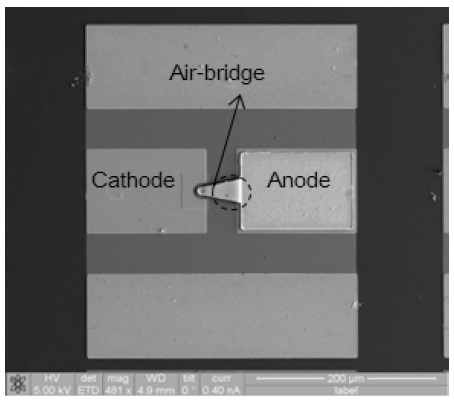
The Schottky diode was fabricated using the heterogeneous resist patterning method. Because the photo lithography process is unsuitable for nanoscale patterning, we performed nano-dot patterning using the e-beam lithography process. The nanoscale dot as the anode is used for the Schottky contact, and the T-shaped disk is used to connect the anode to the air bridge. The e-beam lithography process uses multiple e-beam scans at different doses and a tri-level e-beam resist system that consists of PMMA-950K and PMGI in order to separately pattern the nanoscale dot and the T-shaped disk of the diode anode. After metallization for the diode anode, the air-bridge process was performed by photo lithography in order to connect the anode with the anode pad. Fig. 1 shows a scanning electron microscope (SEM) photograph of the fabricated Schottky diode with a nano-dot structure. Fig. 2 shows a close-up of the fabricated nanoscale dot and T-shaped disk.
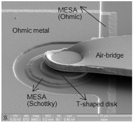
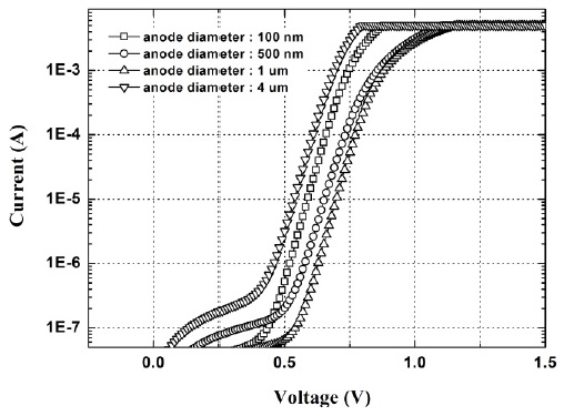
The I–V characteristics of the fabricated Schottky diode were measured using a Keithley 4200-SCS (semiconductor characterization system). The ideality factor (η), current parameter (
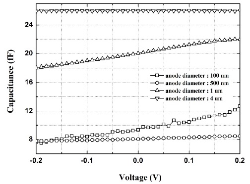
The capacitance-voltage characteristics were measured using an Agilent E4980A Precision LCR Meter. Fig. 4 shows the measured junction capacitance characteristics. The measured total junction capacitance (
III. PERFORMANCE OF THE 94 GHZ SINGLE BALANCED MIXER
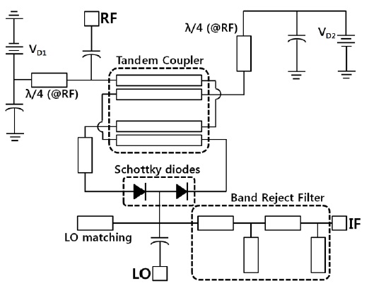
A circuit diagram of the designed 94 GHz single balanced mixer is shown in Fig. 5. The 94 GHz single balanced diode mixer consists of two Schottky diodes with an anode diameter of 500 nm, a tandem coupler, and a band reject filter. A tandem coupler as a W-band balun was used for high LO-to-RF isolation. A quarter wavelength at the LO line was designed to ensure a 180° phase difference between the RF and the LO ports. The LO and RF signals were directed through the metal-insulator-metal (MIM) capacitors, while a band reject filter for suppressing the LO signal was used at the intermediate frequency (IF) stage to extract the desired IF signal.
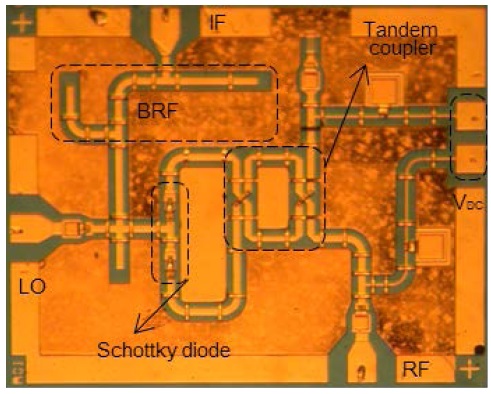
The designed 94 GHz single balanced mixer was fabricated using the standard MMIC process from the Millimeter-Wave Innovation Research Center (MINT), Dongguk University [6]. Fig. 6 shows a SEM photograph of the fabricated 94 GHz single balanced mixer using Schottky diodes with an anode diameter of 500 nm. The total chip size is 1.9 mm × 1.3 mm.
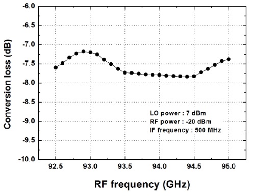
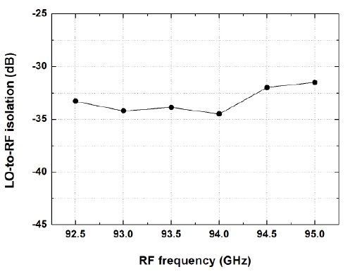
We measured the conversion loss and isolation characteristics of the fabricated mixer by using an Agilent E4407B spectrum analyzer with a 11970W harmonic mixer, an 83558A millimeter-wave source module, voltage-controlled oscillators, and GGB110H probes at a frequency range from 92.5 GHz to 95 GHz. The fabricated mixer had an average conversion loss of -7.58 dB at an RF frequency of 92.5 GHz to 95 GHz with an IF frequency of 500 MHz with an LO power of 7 dBm, as shown in Fig. 7. The RF-to-LO isolation characteristics were greater than -32 dB as shown in Fig. 8.
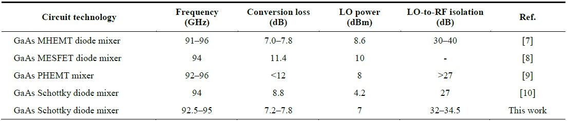
Finally, Table 1 shows a comparison of the W-band MMIC mixers with other published data. Considering the low LO power, the mixer presented in this paper showed a good conversion loss of 7.8 dB at 94 GHz. This improvement can be attributed to the superior Schottky diode characteristics. The fabricated Schottky diode with a nanoscale anode is expected to be applied to terahertz applications.
[Table 1.] Comparison of the W-band MMIC mixer with other published data

Comparison of the W-band MMIC mixer with other published data
In this paper, we developed a 94 GHz low conversion loss, single balanced mixer using planar Schottky diodes on a GaAs substrate. The GaAs Schottky diode has a nanoscale anode with a T-shaped disk, which can yield high cutoff frequency characteristics. The fabricated Schottky diode with an anode diameter of 500 nm exhibits an ideality factor of 1.32, a junction capacitance of 8.03 fF, and a cutoff frequency of 944 GHz. Based on this technology, a 94 GHz single balanced mixer was built. The fabricated mixer shows an average conversion loss of -7.58 dB at an RF frequency of 92.5 GHz to 95 GHz with an IF frequency of 500 MHz and a LO power of 7 dBm. The RF-to-LO isolation characteristics are greater than -32 dB. These values can be attributed to the superior Schottky diode characteristics.