검색 전체 메뉴
PDF
맨 위로
OA 학술지
Performance Evaluation of the Complex-Coefficient Adaptive Equalizer Using the Hilbert Transform
  • 비영리 CC BY-NC
  • 비영리 CC BY-NC
ABSTRACT
Performance Evaluation of the Complex-Coefficient Adaptive Equalizer Using the Hilbert Transform
KEYWORD
Feed-forward equalizer , Inter-symbol interference , Least mean squares algorithm , Quadrature phase-shift keying , Underwater acoustic communication
  • I. INTRODUCTION

    Because of the reflections from the boundaries in underwater acoustic communication, the communication channel used is known to exhibit a frequency-selective fading channel with a multipath delay spread [1-3]. The performance of the underwater acoustic communication system degrades because of the inter-symbol interference (ISI) [4,5] caused by the signals reflected from the sea surface and the sea bottom. A channel estimation-based equalizer is usually adopted to compensate for the ISI effect [5,6].

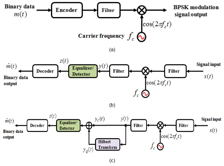
    In this study, a feed-forward equalizer (FFE) with the least mean squares (LMS) algorithm is applied to the quadrature phase-shift keying (QPSK) transmission system in order to cancel out the ISI effect [7,8]. Two types of equalizers are introduced, namely a real-coefficient equalizer and a complex-coefficient equalizer. We also introduced a binary phase-shift keying (BPSK) system with two real- and a complex-coefficient equalizers. For the imaginary part such as the quadrature (Q) channel of the QPSK system, a Hilbert transform was used in the BPSK system [9,10].

    The rest of this paper is organized as follows: in Section II, a comparison of two types of equalizers is presented. In Section III, simulation configurations are introduced. Section IV presents the concept of the complex-coefficient BPSK system. In Section V, the simulation results and the experimental results of the proposed methods are discussed.  A summary of the performance of the proposed method is presented in Section VI.

    II. COMPARISON OF TWO TYPES OF EQUALIZERS

    In general, there are two binary state channels, namely the in-phase (I) channel and the quadrature (Q) channel, in a QPSK modulation and demodulation system, as shown Fig. 1(a). The transmitted signal x(t) on the receiver is separated and demodulated into the output signals yI(t) and yQ(t) by using a cosine signal or a sine signal with the same carrier frequency as that used on the modulation system. Then, the output signals are converted into four-state {1 + j, 1 – j, –1 + j, –1 – j} data from each output yI(t) and yQ(t).

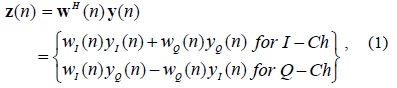
    When an equalizer for the compensation of the channel distortion is applied to the output signals, two types of systems are considered. The first type of system includes two separated real-coefficient equalizers for each output yI(t) and yQ(t), as shown in Fig. 1(b). This system can be considered a separated two BPSK system. The other is a complex-coefficient equalizer for the merged output signal y(t) = yI(t) + jyQ(t), shown in Fig. 1(c).

    III. SIMULATION CONFIGURATIONS

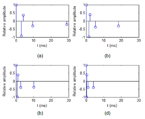
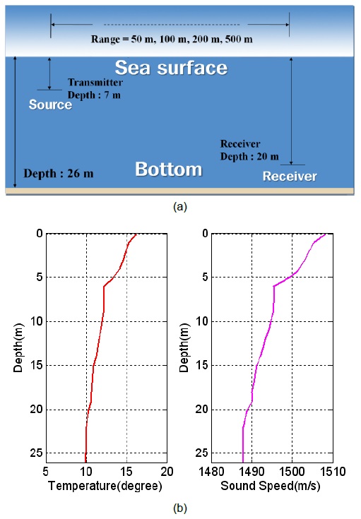
    Fig. 2 shows a layout of the experimental geometry at the bay of the Gwangan Beach located on the east side of Busan city, Korea. The range between the transmitter and the receiver is set to be 50, 100, 200, and 500 m. The depths of the transmitter and the receiver are set to be 7 m and 20 m, respectively. As the temperature and the sound speed of the vertical depth were almost flat, an image method [11] was used for the implementation of the underwater acoustic communication channel, and the related channel impulse responses are shown in Fig. 3.

    We assumed that the channel response had five impulse signals: direct signal, surface-reflected signal, bottom-reflected signal, surface-bottom-reflected signal, and bottom-surface-reflected signal. The sampling frequency and the carrier frequency are set to be 160 kHz and 20 kHz, respectively. The transmission rates are set to be 500, 1000, 2000, and 4000 symbols per second (sps). The transmitted image is a standard Lena image that consists of 50 × 50 pixels with an 8-bit resolution (20,000 bits).

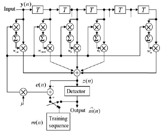
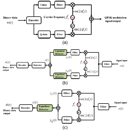
    Fig. 4 shows the block diagram of the FFE with the LMS algorithm. Here, m(n), y(n), z(n), e(n), and denote binary data in the modulation system, the channel output, the equalizer output, the error signal, and the decision output, respectively. The LMS algorithm is used for the determination of the coefficient on the equalizer to compensate for the ISI. The FFE consists of a transversal finite impulse response filter with 30 taps. The filter output, the estimation error, and the tap-weight adaptation are represented as discussed in [5].

    image
    image
    image

    where H, *, and μ denote the Hermitian form, the complex conjugate, and the step size parameter, respectively.

    IV. CONCEPT OF COMPLEX BPSK SYSTEM

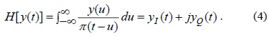
    In this section, we introduce a complex BPSK system based on the concept of the QPSK system. The BPSK system has the same structure as the I channel of the QPSK system and has two states {1, –1}. To obtain the Q-channel signal, a Hilbert transform was adopted. The Hilbert transform can be represented as follows [9,10]:

    image

    It was obtained using the imaginary signal yQ(t) with a 90° phase shift from the original real signal yI(t). The imaginary part of the binary data in the modulation system m(n) was also calculated for obtaining estimation error in Eq. (2). The BPSK modulation and demodulation system with a real-coefficient equalizer and a complex-coefficient equalizer is shown in Fig. 5.

    V. RESULTS AND DISCUSSIONS

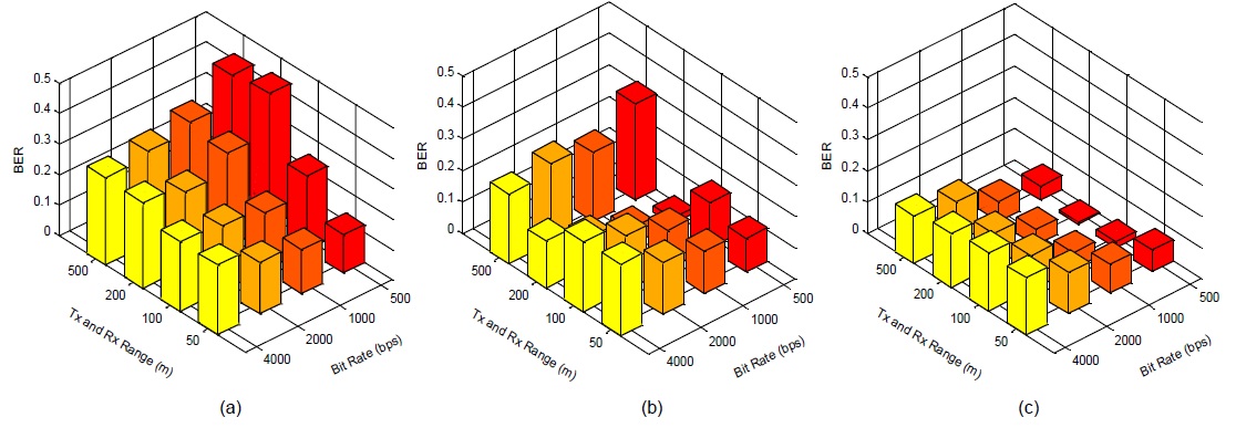
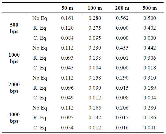
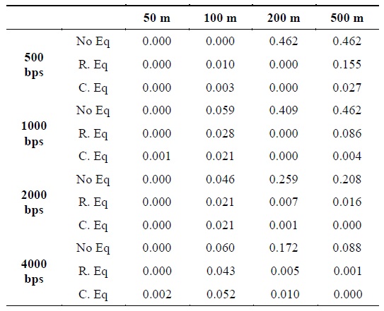
    First, the simulation results of two different equalizers of the QPSK system are presented. The bit error rates (BERs) according to the transmission rate and the range are presented in Fig. 6 and Table 1, respectively.

    [Table 1.] Comparison of results obtained using the QPSK system with two different types of equalizers

    label

    Comparison of results obtained using the QPSK system with two different types of equalizers

    In Fig. 6, (a) shows the result obtained without the use of an equalizer; (b) the result obtained using two real-coefficient equalizers; and (c) the result obtained using a complex-coefficient equalizer. The same number of iterations for the training of the coefficient on the FFE is set for each simulation. From the obtained results, we concluded that the complex-coefficient LMS equalizer shows a better performance than the two separated real-coefficient LMS equalizers. The filter’s output signal z(n), error signal e(n), and tap-weight vector w(n) have a cross-coupling system between them, as shown in Eqs. (1)–(3). This implies that a complex LMS algorithm is equivalent to a set of four real LMS algorithms because of the cross-coupling system between the filter output signal, the error signal, and the tap-weight vector. From Fig. 6, we can infer that the results obtained in the case of the low sps and the long range were better than those obtained in the case of the high sps and the short range.

    Second, Fig. 7 and Table 2 show the simulation results of two different equalizers in the BPSK system. In Fig. 7, (a) shows the result obtaining without using the equalizer; (b) the result obtained using a real-coefficient equalizer; and (c) the result obtained using a complex-coefficient equalizer. The same number of iterations for the training of the coefficient on the FFE is set for all the simulations. Further, the results obtained using the complex-coefficient LMS equalizer were better than those obtained using the real-coefficient LMS equalizer in the BPSK system.

    [Table 2.] Comparison of results obtained using the BPSK system with two different types of equalizers

    label

    Comparison of results obtained using the BPSK system with two different types of equalizers

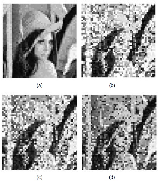
    Finally, Fig. 8 shows the results of the equalization of the experimental data, carried out in a shallow ocean. The experimental conditions are the same those as shown in Fig. 1. The distance between the transmitter and the receiver was 10 m, and the bit rate was chosen to be 50 sps. In Fig. 8, (a) shows an original Lena image, (b) presents the result obtained without using an equalizer (BER=0.224), (c) and (d) illustrate the results with two real-coefficient equalizers (BER=0.181) and a complex-coefficient equalizer (BER= 0.123), respectively. Therefore, we can conclude that the complex-coefficient equalizer performs better than the two real-coefficient equalizers.

    VI. CONCLUSIONS

    In this study, an FFE with the LMS algorithm was applied to the QPSK system, and two real-coefficient equalizers and a complex-coefficient equalizer were adopted; their results were compared. The performance of a complex-coefficient equalizer was better than that of the two real-coefficient equalizers. On the basis of the results of the QPSK system, a Hilbert transform was applied to the real-coefficient BPSK system in order to obtain the complex-coefficient BPSK system. Further, the performance of a complex-coefficient equalizer was better than that of the two real-coefficient equalizers in the BPSK system.

참고문헌
  • 1. Yang T. C. 2012 “Properties of underwater acoustic communication channels in shallow water,” [Journal of the Acoustical Society of America] Vol.131 P.129-145 google cross ref
  • 2. Aik T. B., Sen Q. S., Nan Z. 2006 “Characterization of multipath acoustic channels in very shallow waters for communications,” [in Proceeding of OCEANS 2006 ? Asia Pacific] P.1-8 google
  • 3. Yang W. B., Yang T. C. 2006 “High-frequency channel characterization for M-ary frequency-shift-keying underwater acoustic communications,” [Journal of the Acoustical Society of America] Vol.120 P.2615-2626 google cross ref
  • 4. Park J., Yoon J. R., Park J. S. 2009 “Frequency and temporal coherence variation for sea surface fluctuation,” [Japanese Journal of Applied Physics] Vol.48 google
  • 5. Park J., Park K. C., Yoon J. R. 2010 “Underwater acoustic communication channel simulator for flat fading,” [Japanese Journal of Applied Physics] Vol.49 google
  • 6. Kim J., Park K. C., Park J., Yoon J. R. 2011 “Coherence bandwidth effects on underwater image transmission in multipath channel,” [Japanese Journal of Applied Physics] Vol.50 google
  • 7. Yoon Y. H., Zielinski A. 1995 “Simulation of the equalizer for shallow water acoustic communication,” [in Proceeding of OCEANS 1995] P.1197-1203 google
  • 8. Haykin S. S. 1996 Adaptive Filter Theory google
  • 9. Proakis J. G. 2008 Digital Communications google
  • 10. Carlson A. B. 1986 Communication Systems google
  • 11. Jenson F. B., Kuperman W. A. 1984 Computational Ocean Acoustics google
OAK XML 통계
이미지 / 테이블
  • [ Fig. 1. ]  Block diagrams of the QPSK communication system: (a) QPSK modulation system, (b) QPSK demodulation system with two real-coefficient equalizers, and (c) QPSK demodulation system with a complex-coefficient equalizer.
    Block diagrams of the QPSK communication system: (a) QPSK modulation system, (b) QPSK demodulation system with two real-coefficient equalizers, and (c) QPSK demodulation system with a complex-coefficient equalizer.
  • [ Fig. 2. ]  Schematic layout of the experiment: (a) experimental configuration and (b) temperature and sound speed profiles.
    Schematic layout of the experiment: (a) experimental configuration and (b) temperature and sound speed profiles.
  • [ Fig. 3. ]  Channel impulse responses according to distances: (a) 50 m, (b) 100 m, (c) 200 m, and (d) 500 m.
    Channel impulse responses according to distances: (a) 50 m, (b) 100 m, (c) 200 m, and (d) 500 m.
  • [ ] 
  • [ ] 
  • [ ] 
  • [ Fig. 4. ]  FFE with LMS algorithm.
    FFE with LMS algorithm.
  • [ ] 
  • [ Fig. 5. ]  BPSK communication system: (a) BPSK modulation system, (b) BPSK demodulation system with a real-coefficient equalizer, and (c) BPSK demodulation system with a complex-coefficient equalizer.
    BPSK communication system: (a) BPSK modulation system, (b) BPSK demodulation system with a real-coefficient equalizer, and (c) BPSK demodulation system with a complex-coefficient equalizer.
  • [ Fig. 6. ]  Comparison of results obtained using two different types of equalizers: (a) no equalizer, (b) with two real-coefficient equalizers, and (c) with a complex-coefficient equalizer.
    Comparison of results obtained using two different types of equalizers: (a) no equalizer, (b) with two real-coefficient equalizers, and (c) with a complex-coefficient equalizer.
  • [ Table 1. ]  Comparison of results obtained using the QPSK system with two different types of equalizers
    Comparison of results obtained using the QPSK system with two different types of equalizers
  • [ Fig. 7. ]  Comparison of results using two different types of equalizers: (a) no equalizer, (b) using a real-coefficient equalizer, and (c) using a complex-coefficient equalizer.
    Comparison of results using two different types of equalizers: (a) no equalizer, (b) using a real-coefficient equalizer, and (c) using a complex-coefficient equalizer.
  • [ Table 2. ]  Comparison of results obtained using the BPSK system with two different types of equalizers
    Comparison of results obtained using the BPSK system with two different types of equalizers
  • [ Fig. 8. ]  Experimental results: (a) original, (b) without the equalizer, (c) with real-coefficient equalizers, and (d) with a complex-coefficient equalizer.
    Experimental results: (a) original, (b) without the equalizer, (c) with real-coefficient equalizers, and (d) with a complex-coefficient equalizer.
(우)06579 서울시 서초구 반포대로 201(반포동)
Tel. 02-537-6389 | Fax. 02-590-0571 | 문의 : oak2014@korea.kr
Copyright(c) National Library of Korea. All rights reserved.