The number of deaths caused by a brain stroke has rapidly increased over the years. The interest in microwave brain stroke localization has drawn people’s interest because of its low cost and portability [1]. Several research groups have reported microwave imaging systems or devices [2-6]. To validate the effectiveness of microwave imaging methods, a phantom imitating human head in electrical and anatomical aspects is required [6-8]. General human phantoms for specific absorption rate (SAR) tests aim to mimic human body in a narrow frequency band which is not suitable for a microwave imaging method requiring the broadband (0.5–2 GHz) characteristics [9, 10]. Several wideband phantoms have a simple rectangular shape or are too homogeneous, which makes them too simple to model an actual brain stroke [5, 8]. There is a head phantom using a commercial plastic skull model with layered tissue but the model is too simple to match well with actual brain for electromagnetic (EM) analysis [8]. In this paper, a head phantom for evaluation of a brain stroke localization is proposed. Firstly, molds for the proposed phantom was printed by 3D printer to imitate EM simulation setup in structural aspect. After that, 4 different brain tissue materials (spinal cord, cerebellum, white matter, and cerebrospinal fluid) were fabricated with polyethylene (PE) powder, agar, Tx-151, NaCl, NaN3, and distilled water as infilled materials of the phantom. Blood material was additionally fabricated for simulating stroke event with the same ingredients aforementioned. The electrical properties of the brain tissue materials and blood material in the frequency band from 0.5 to 2 GHz are very close to those suggested in [11]. The brain phantom was fabricated with the molds and 4 brains tissue materials. At the last stage, blood material is implanted as it is demanded.
1. Molds for the Brain Phantom
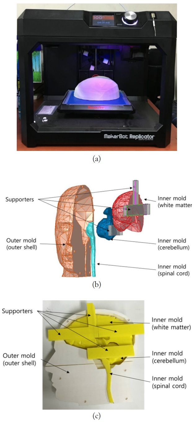
Dimensions for the molds of a phantom (height, 265 mm; sagittal width, 260 mm; coronal width, 197 mm; and thickness of mold, 8–12 mm) are the same as brain CAD data provided by ANSYS HFSS (ver. 14). However, the CAD data could not be applied directly to the phantom molds since the data had holes and overlapping parts. The ANSYS CAD data was modified to enclose each brain tissue and to eliminate overlapped parts. In addition, the oval and nasal cavities were eliminated. The brain model was printed as molds by MakerBot 3D printer whose resolution was 0.1 mm [12]. Fig. 1(a) shows the 3D printer. Even though the real brain consists of a lot of tissues, the brain was subdivided into 4 major tissues (spinal cord, cerebellum, white matter, and cerebrospinal fluid) in our head phantom model. The printed molds consist of outer parts and inner molds, including white matter, cerebellum, and spinal cord, as shown in Fig. 1(b) and (c). The outer molds were used as the outer shell of the brain phantom, while the inner molds were used to separate and shape the brain tissue materials, and were extracted after the tissues solidified. The inner molds were used only for shaping and locating the brain tissue materials. Spinal cord, cerebellum, and white matter among the subdivided 4 major brain tissues were embedded with supporters to main the proper locations. The filament used for making the molds is polylactic acid (PLA) and its relative permittivity is about 2.0.
2. Recipes for the Blood and Brain Tissue Materials
Recipes for the 4 brain tissue materials and blood material were developed such that the electrical properties of the phantom should be similar to those in [11]. The fabricated blood material was used for simulating a blood clot caused by a brain stroke. Each brain tissue material consists of PE powder, agar, Tx-151, NaCl, NaN3, and distilled water. Distilled water (
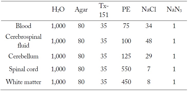
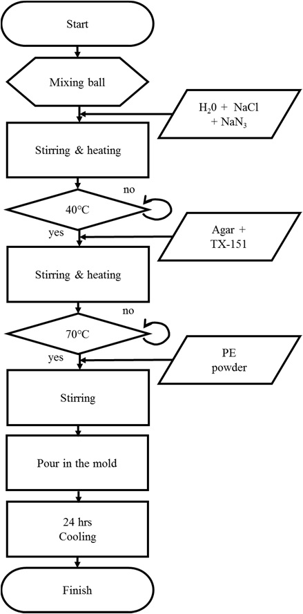
TX-151 and agar were used for gelification and solidification, respectively. NaN3 was added as a preservative. Ingredient proportion of each brain tissue material is shown in Table 1. Fig. 2 shows the fabrication procedure of brain tissue materials and the detailed procedure is described below.
[Table 1.] Ingredient proportion of each brain tissue material (unit, g)

Ingredient proportion of each brain tissue material (unit, g)
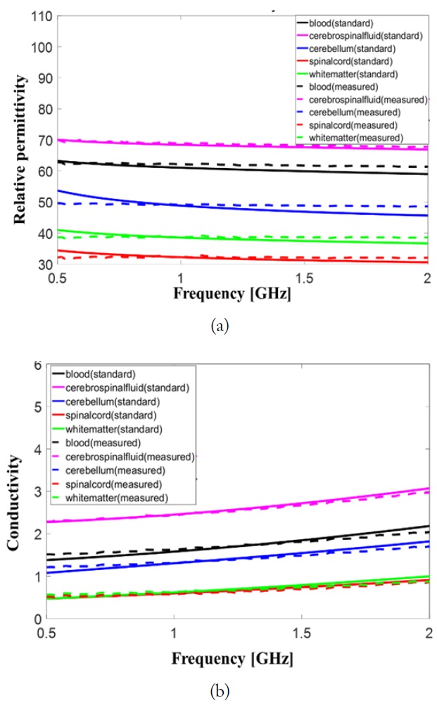
Permittivity and conductivity of the fabricated brain tissue materials and blood material were measured after 24 hours with Agilent 85070E dielectric probe kit and 8719ES network analyzer. The measured permittivity and conductivity values of the brain tissue materials consisting brain phantom should have less than 10% error comparing to those suggested in [11]. The measured data and standard data were compared in Fig. 3. Relative permittivities of the brain tissues are varied less than 10 % in the frequency band from 0.5 to 2 GHz the dispersive characteristic of the conductivity of fabricated brain tissue materials is very similar to that of real brain tissue given in [11]. The maximum error in the conductivity was observed in blood material at 2 GHz and is less than 10%.
To evaluate imaging method for brain stroke localization, a 4-layered brain phantom with blood material simulating blood clot was needed.
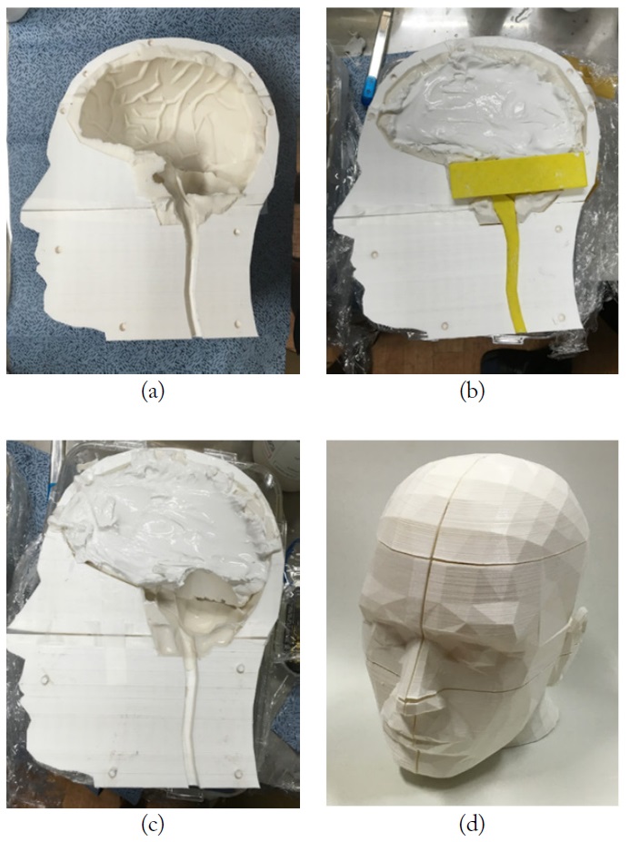
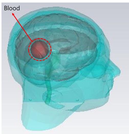
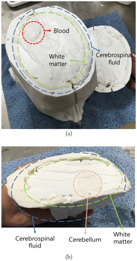
To fabricate the 4-layered phantom, cerebrospinal fluid brain tissue materials was poured into the outer shell while other inner molds were remaining. After the material was firmly solidified, the inner molds were taken off as shown in Fig. 4(a). To fabricate other layers, the aforementioned procedure was repeatedly performed in the following order: white matter, cerebellum, and spinal cord as shown in Fig. 4(b) and (c). The halves of the phantom were put together as shown in Fig. 4(d). As the last procedure, blood tissue material was shaped and located at the position where the blood clot, simulating brain stroke, was placed in the EM simulation as shown in Figs. 5 and 6. Fig. 6 shows cross section of the final manufactured brain phantom with blood material.
In this paper a brain phantom for evaluating brain stroke localization is proposed. Outer shell of the proposed phantom was printed by 3D printer and 4 different brain tissue and blood materials were fabricated and located in the printed molds. The brain phantom imitated a brain model in EM simulation in terms of electrical properties similar to those provide in [11] and structural shape. Thus the proposed phantom can be used to validate the effectiveness of microwave imaging methods and provide a means of comparison between measurement and simulation for evaluating brain stroke localization.