Wireless power transfer has long been a topic of interest in the scientific community. Kurs et al. [1] used coupled-mode theory (CMT) to analyze the characteristics of a wireless power transfer system (WPTS) using the near field. Following this, many research papers on non-radiative magnetically coupled WPTSs were published [2-5], which demonstrated the potential to deliver power more efficiently than traditional inductive systems. Also, there have been several reports on the theoretical analysis of wireless power transmission (WPT) using CMT to propose or test multi-coil inductive links, which can considerably increase the power transfer efficiency (PTE) at large coupling distances [1, 6]. Alternatively, the design and optimization of inductive power transfers have been studied from a circuit perspective [7, 8]. However, in-depth comparison between CMT and circuit-based theory, especially in transient mode, is still lacking.
To clarify the relationship between these two theories, we analyzed the WPTS theoretically, using CMT in the time-domain analysis [9] and compared it with the result using equivalent circuit analysis [10]. We found that CMT-based transient solutions are not exactly the same as those from the circuit-based solutions in predicting energy exchanges between resonators. However, CMT-based analysis gives an approximate analytical transient solution that can be used to provide qualitative insight into the energy transfer mechanism in the WPTS.
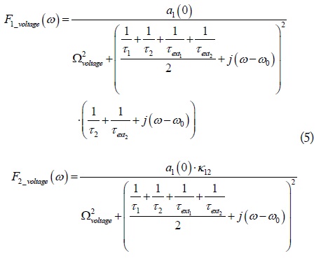
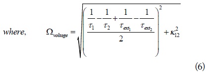
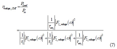
Using a Fourier transformation of the transient CMT, the efficiency of the WPTS using either a power or voltage source at resonant frequency can be derived easily. It matches well with the efficiency based on steady-state equivalent circuit theory.
The critical coupling coefficient is derived in the time domain with the resonator quality factor (Q). A criterion is suggested to distinguish inductive coupled and magnetic resonant coupled WPT in terms of critical distance corresponding to critical coupling.
II. THE COUPLING OF TWO RESONATOR MODES
1. Analysis of a WPTS Using CMT in the Time Domain
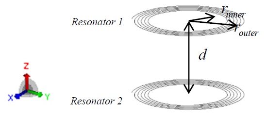
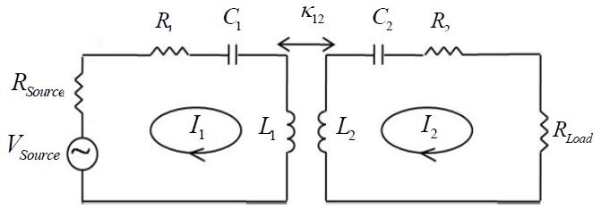
The structure of the proposed WPTS is illustrated in Fig. 1. The transmitting and receiving antennas consist of multi-turn spiral coils. Each coil acts as a high Q RLC tank resonator. The two coils are coupled by mutual inductance, which is a function of the geometry of the coils and the distance between them. One of the resonators transfers the energy supplied by the source to the load of the other resonator.
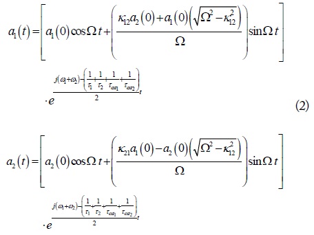
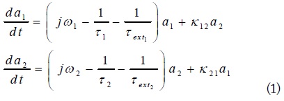
A time-domain solution for the energy exchange between two coupled resonators may be useful in understanding the coupling mechanism between them. Consider the equation for the mode amplitudes

The variable
2. Derivation of PTE in the WPTS Using CMT

In steady state, the field amplitude inside the resonator is held constant, namely,
where
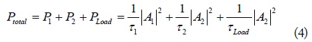
Using the field amplitude and decay rate of each resonator, the PTE in WPTS is

3. Validation of the Time-Domain Solution of WPTS Using CMT
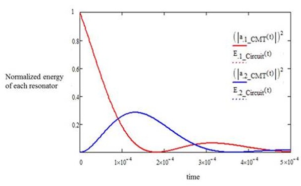
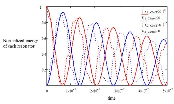
In order to show the validity of the time-domain solution of the WPTS using CMT, the equivalent circuit of the same WPTS is used as shown in Fig. 2. The total energy stored in each resonator is obtained by calculating the sum of electric energy in the capacitor and the magnetic energy in the inductor. In Figs. 3 and 4, we compare the results obtained by CMT and the equivalent circuit for two different conditions of the Q and coupling coefficient when the unit energy is input into one of the resonators at the time
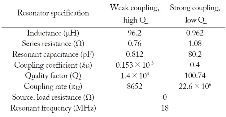
Specification parameters for the transient solution of energy in each resonator in the equivalent circuit [12]
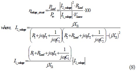
The PTE derived from Fig. 2 at a given frequency, ω, using equivalent circuit theory is Eq. (8) [8].

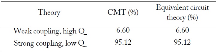
As seen above, two cases are used to verify the derived PTE equations. The values of PTE calculated by CMT and equivalent circuit theory at a resonant frequency match well (see Table 2). Even though the time-domain CMT solution is somewhat inaccurate in predicting the transient energy storage in each resonator, it appears to be useful enough to allow for an understanding of the energy exchange process qualitatively between the two resonators. Also, this CMT analysis can be applied to two asymmetric resonator cases because the decay rates are defined for internal and external loss independently.
[Table 2.] Values of PTE calculated by CMT and equivalent circuit model

Values of PTE calculated by CMT and equivalent circuit model
III. CRITERION FOR DISTINGUISHING INDUCTIVE COUPLED AND MAGNETIC RESONANCE COUPLED WPTS
1. Derivations of the Critical Coupling Coefficient
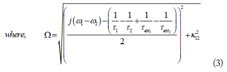
The critical coupling coefficient,
As shown in Figs. 3 and 4, the two resonators in the WPTS exchange energy continuously, starting from the unit input energy in resonator 1. The energy goes back and forth between the two resonators until all the input energy is dissipated in the WPTS. The critical coupling coefficient,
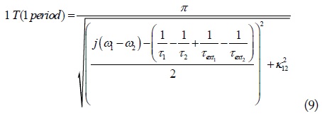
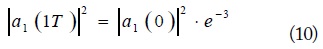
Using Eq. (9), the critical coupling coefficient can be achieved when the maximum return energy after one period is 5 % (i.e., e-3 times) of initial transmitted energy

Using Eqs. (2) and (3), the equation of
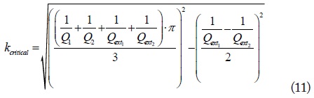
where
2. Simulation Results and Discussion
Consider the WPTS shown in Fig. 1 where the transmitting and receiving resonators have an inner radius of 0.2 m and an outer radius of 0.3 m. All coils are made of 2-mm-diameter copper and spiral inward 5.7 turns. The series-connected variable capacitors are used to tune the system to 10.03 MHz.
The equivalent circuit of the WPTS shown in Fig. 2 has the circuit parameters
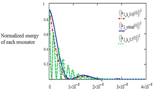
The coupling coefficient,
Fig. 5 shows the energy stored in the transmitting resonator when
Even though there are many articles that have mentioned inductive coupled WPTS and magnetic resonance coupled WPTS, it seems that all the WPTSs composed of two magnetic resonators (coils) have the same characteristics with respect to the distance between two resonators. They become overcoupled, critically coupled, and then under-coupled WPTSs as the distance between the two resonators becomes larger. Therefore, there seems to be no difference in the power transfer mechanism in magnetic WPTSs.
However, from a practical point of view, a WPTS may be called inductive coupled if the critical distance,
A WPTS is theoretically analyzed in a time-domain using CMT when unit energy is applied to one of two resonators. By Fourier transforming the transient CMT, the equation for the PTE of the WPTS at resonant frequency is derived. The CMT transient solutions are compared with the equivalent circuit-based solutions. We found that the inaccuracy of CMT in the WPTS analysis of a time-domain is due to the assumption of the frequency-independent Q and coupling coefficient of the resonators in the CMT model. Based on the time-domain CMT solution, the critical coupling coefficient is derived using the Q of the WPTS. The critical distance corresponding to critical coupling is suggested as a criterion for distinguishing inductive coupled and magnetic resonance coupled WPTSs.


![Specification parameters for the transient solution of energy in each resonator in the equivalent circuit [12]](http://oak.go.kr/repository/journal/20451/E1ELAT_2016_v16n4_219_t001.jpg)