검색 전체 메뉴
PDF
맨 위로
OA 학술지
A Reconfigurable Directional Coupler Using a Variable Impedance Mismatch Reflector for High Isolation
  • 비영리 CC BY-NC
  • 비영리 CC BY-NC
ABSTRACT
A Reconfigurable Directional Coupler Using a Variable Impedance Mismatch Reflector for High Isolation
KEYWORD
Antenna Front-End , High Tx/Rx Isolation , Reconfigurable Coupler , Reconfigurable Duplexer , Variable Reflector
  • I. INTRODUCTION

    Radio-frequency identification (RFID) readers rely on the isolation characteristics of the Tx and Rx paths in the antenna front end, since the Tx leakage directly affects the Rx sensitivity. The bi-static architecture where Tx and Rx antennas are used separately can achieve high isolation characteristics, but this increases the system size and cost. Thus, a monostatic architecture is preferable in an RFID reader system, since it only requires a single antenna, thereby giving a smaller size and lower cost. The correct application of the monostatic architecture to an RFID reader requires resolution of the degradation in Rx sensitivity due to Tx.

    Many studies have adopted the use of Tx leakage cancellers that are configured by a range of different structures, including multiple hybrid couplers [1], quadrature feedback circuits [2], variable attenuators, phase shifters controlled by micro-controller units (MCUs) [3], and single impedance mismatch reflectors [4]. However, these previously proposed structures impose a large size and design complexity to achieve the required leakage suppression. The architecture with a single impedance mismatch reflector also undergoes a limited range of Tx leakage cancellation due to the fixed impedance in the reflector. These limitations emphasize the need for a new type of reconfigurable coupler that can be used to suppress Tx leakage in a mono-static RFID reader front end with a simple implementation, as is proposed in this letter.

    II. CIRCUIT DESIGN AND ANALYSIS

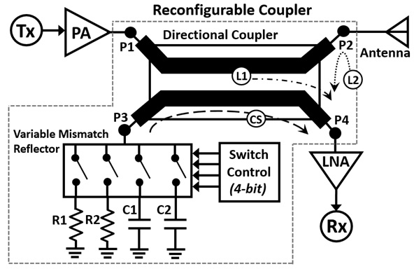
    Fig. 1 shows the proposed reconfigurable directional coupler in the RFID front end. Referring to Fig. 1, Tx leakage generally consists of the coupled signal from the Tx port to the isolation port due to the intrinsic isolation characteristic of the directional coupler (L1) and the reflected signal due to the antenna impedance mismatch (L2). These unwanted leakages are canceled by having the proposed structure adopt a variable impedance mismatch reflector to generate the leakage-cancelling signal from port 3 of the directional coupler. The leakage-cancelling signal is determined by the impedance loaded at port 3 of the directional coupler. If the transmission coefficient (T), coupling factor (C), the isolation characteristic (I) of the directional coupler, and the reflection coefficient (ΓA) of an arbitrary antenna are known, then the required reflection coefficient of the variable mismatch reflector (Γ) at port 3 of the directional coupler is determined by:

    image

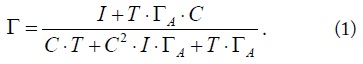
    The values of Γ determine the cancellation of the Tx leakage flows to the Rx (port 4 of the directional coupler). That is, if multiple values for Γ can be generated according to the antenna impedance variations, then the Tx leakage can be cancelled regardless of the antenna load conditions.

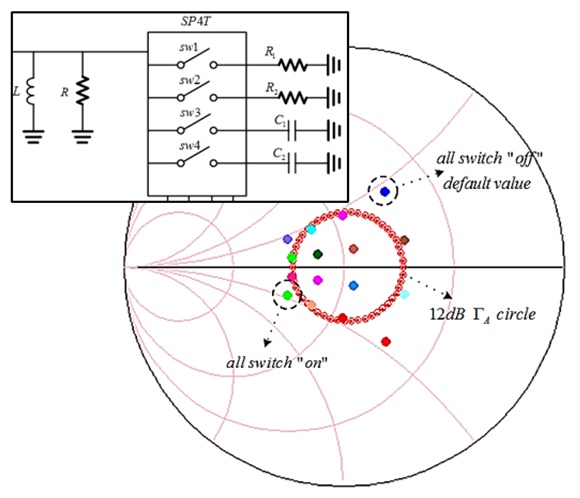
    Since determination of Γ depends on varying the antenna matching conditions by the circumstances of system usage, Γ must also be controllable according to the values of ΓA. As shown in Fig. 1, a SP4T switch is connected with different loads R1, R2, C1, and C2. The combination of these impedances can generate a total of 16 (=24) different Γs. Fig. 2 shows the simulated results for different Γ generations obtained by adopting different R1, R2, C1, and C2 values to cover the range for an antenna return loss of less than 12 dB. When all switches are off, the default impedance is set by the parallel connection of R and L, as shown in Fig. 2, instead of the high impedance due to the open state. Thus, manipulation of the different Γs produced by different combinations of loads connected through SP4T cancels the Tx leakage under variable circumstances.

    III. MEASUREMENT

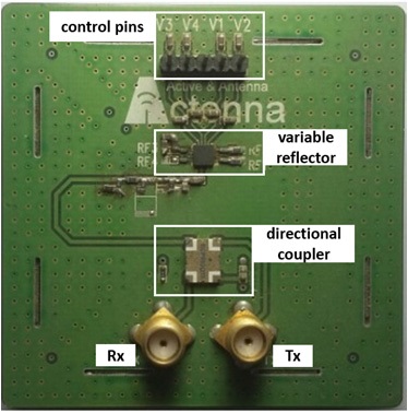
    The proposed reconfigurable directional coupler was implemented with a LTCC 10-dB directional coupler from RN2 Technology and a SP4T (MASW-007813) from MACOM. The discrete load impedances were implemented using R = 90 Ω, L = 19 nH, R1 = 140 Ω, R2 = 70 Ω, C1 = 1 pF, and C2 = 2 pF. Fig. 3 shows the implemented reconfigurable directional coupler with a variable impedance mismatch reflector. The isolation characteristics of the reconfigurable coupler in the RFID front end were found using a commercially available quadrifilar spiral antenna (QSA) with 12 dB return loss at 917 MHz, as shown in Fig. 4. Referring to Fig. 1, the Tx/Rx isolation characteristics of the antenna were measured by the S-parameters from port 1 to port 4. Fig. 5 shows the selective measured isolation characteristics using the proposed variable mismatch reflector. Termination of port 3 of the 10-dB directional coupler with 50 Ω gave an isolation of about 25 dB at 917 MHz. Instead of using the 50 Ω load, the proposed variable mismatch reflector was connected to port 3 of the directional coupler and the maximum isolation of 45 dB was measured at 917 MHz when the switches 1 and 3 were turned on as shown in Fig. 5. Therefore, the proposed reconfigurable coupler showed an improvement of more than 20 dB in the isolation characteristics when compared to the conventional directional coupler architecture in the RFID front end.

    IV. CONCLUSION

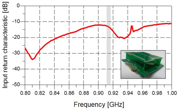
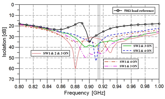
    This letter describes a reconfigurable directional coupler that uses a variable impedance mismatch reflector to enhance the isolation characteristics. The variable impedance mismatch reflector could generate multiple reflection coefficients to cancel the Tx leakage, which varied according to the antenna load impedances. Setting the proper load impedance through the proposed reflector resulted in an improvement of more than 20 dB in the isolation characteristics at the RFID operation band.

참고문헌
  • 1. Lim W. G., Park S. Y., Son W. I., Lee M. Q., Yu J. W. 2009 "RFID reader front-end having robust Tx leakage canceller for load variation," [IEEE Transactions on Microwave Theory and Techniques] Vol.57 P.1348-1355 google cross ref
  • 2. Pursula P., Kiviranta M., Seppa H. 2009 "UHF RFID reader with reflected power canceller," [IEEE Microwave and Wireless Components Letters] Vol.19 P.48-50 google cross ref
  • 3. Jung J. W., Roh H. H., Kim J. C., Kwak H. G., Jeong M. S., Park J. S. 2008 "Tx leakage cancellation via a micro controller and high Tx-to-Rx isolations covering an UHF RFID frequency band of 908?914 MHz," [IEEE Microwave and Wireless Components Letters] Vol.18 P.710-712 google cross ref
  • 4. Kim W. K., Na W., Yu J. W., Lee M. Q. 2008 "A high isolated coupled-line passive circulator for UHF RFID reader," [Microwave and Optical Technology Letters] Vol.50 P.2597-2600 google cross ref
OAK XML 통계
이미지 / 테이블
  • [ ] 
  • [ Fig. 1. ]  Block diagram of the proposed reconfigurable coupler in the RFID front end.
    Block diagram of the proposed reconfigurable coupler in the RFID front end.
  • [ Fig. 2. ]  Variable Γ generations by a variable mismatch reflector consisting of an SP4T switch and different impedances.
    Variable Γ generations by a variable mismatch reflector consisting of an SP4T switch and different impedances.
  • [ Fig. 3. ]  Implemented reconfigurable directional coupler with a variable impedance mismatch reflector.
    Implemented reconfigurable directional coupler with a variable impedance mismatch reflector.
  • [ Fig. 4. ]  Measured antenna input return characteristic.
    Measured antenna input return characteristic.
  • [ Fig. 5. ]  Measured isolation characteristic of the reconfigurable directional coupler according to different reflector values.
    Measured isolation characteristic of the reconfigurable directional coupler according to different reflector values.
(우)06579 서울시 서초구 반포대로 201(반포동)
Tel. 02-537-6389 | Fax. 02-590-0571 | 문의 : oak2014@korea.kr
Copyright(c) National Library of Korea. All rights reserved.