검색 전체 메뉴
PDF
맨 위로
OA 학술지
Optimum Array Configuration to Improve Null Steering Time for Mobile CRPA Systems
  • 비영리 CC BY-NC
  • 비영리 CC BY-NC
ABSTRACT
Optimum Array Configuration to Improve Null Steering Time for Mobile CRPA Systems
KEYWORD
Antenna Array , Controlled Reception Pattern Antenna Array , GPS Antenna Array , Interference Mitigation
  • I. INTRODUCTION

    A controlled reception pattern antenna (CRPA) array is widely used for a global positioning system (GPS) in various mobile applications, such as ground vehicles, ships, and aircraft. These applications adopt the CRPA array to suppress interference by forming a pattern null to the direction of an interference source in accordance with array weights iteratively updated by a space–time adaptive processing (STAP) algorithm. Although this iterative process performs well in a stationary system, the process is known to be less functional in a mobile environment because of the fast-varying direction of interference. For this reason, the null steering time has become an emerging consideration in mobile CRPA systems. However, only a few studies have reported on reducing the null steering time by developing a fast adaptive algorithm from a signal processing perspective [16].

    This paper proposes an optimum array configuration to improve the null steering time for mobile CRPA systems. The proposed array is composed of nine uniformly distributed auxiliary elements with a reference element at the center of the array. The array radius is adjusted to optimize the null steering time, and the vertical placement of the center element is varied to suppress undesired side nulls in the upper hemisphere. Adaptive array patterns are computed using a microstrip patch antenna from Amotech [7], and their array weights are obtained from a constrained least mean square (LMS) algorithm [8]. The suitability of the proposed array is evaluated by comparing its null steering performance with a planar arrangement with the same number of elements. The results demonstrate that the steering time can be significantly improved with raised side-null gain by adjusting the array radius of the auxiliary element and the vertical placement of the center element.

    II. PROPOSED ARRAY CONFIGURATION

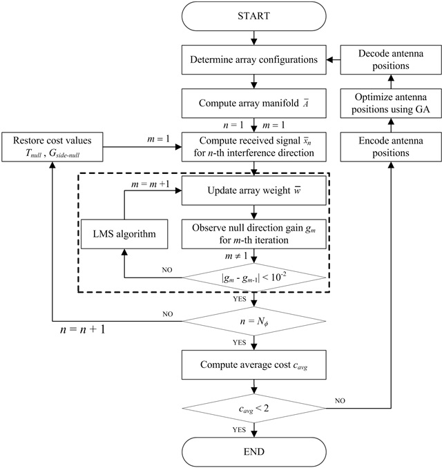
    Fig. 1 presents a flowchart of our optimization process using a genetic algorithm (GA). The process is adopted to determine the optimum array radius and vertical placement of the center element in conjunction with the LMS algorithm for reduced null steering time. The null steering time is defined as the number of iterations to fully mitigate the effect of interference on the LMS algorithm. The process begins with determining an array configuration to compute an array manifold composed of steering vectors for all angles of elevation (θ) and azimuth (ϕ). The vectors are obtained from the amplitude and phase information of the port currents induced by a plane wave source located at every 1° in both azimuth and elevation directions. Ten satellites are assumed to exist in the upper hemisphere, and a single interference source is incident on the array aperture at an angle of θ = 85°. This angle is chosen because most of the null steering operations are conducted for distant sources, and their incident angles are usually near the azimuth plane (x-y plane, z = 0). The GPS signal is modulated by binary phaseshift keying at 1.57542 GHz, and its power is assumed to be –130 dBm, which is lower than the system noise level of –110 dBm, at the array aperture [9]. The interference signal is modeled as a linear chirp with a frequency range of 1.45–1.65 GHz and incident power of –50 dBm, which implies that the interference-to-noise ratio is 60 dB. To estimate the null steering time, an adaptive array pattern is computed by iteratively updating array weights using a constrained LMS algorithm [8]. When updating the array weights, a covariance matrix is computed at every iteration using five snapshots. The gain value of the pattern at the interference direction is observed to calculate the gain difference between the previous and the current iterations as shown by the dashed box in Fig. 1. Then, the null steering time is computed when the gain difference between iterations is less than 0.01 dB or when the power of interference is lower than the noise level. In our process, the side-null gain is also taken into account to prevent the blind area from having a gain value of less than –10 dBic in the upper array pattern (θ ≤ 75°) after the null steering iterations. These cost values are then averaged after conducting several independent simulations for the interference sources located at ϕ = 0°, 30°, ⋯, and 330° as shown in Eq. (1).

    image

    where Tnull(ϕ) indicates the null steering time at each interference direction, and Gnull(ϕ) denotes the side-null gain after the null steering process. The average values of these two metrics are weighted by constant α (0.1) and β (0.01), respectively, and summed up to define a convergence criterion of Cavg< 2 for our optimization process using the GA [10,11].

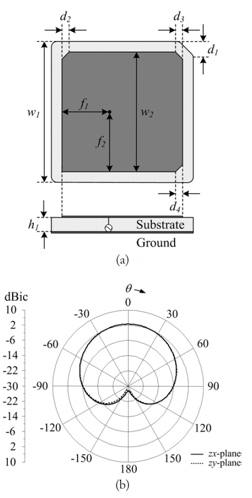
    Fig. 2(a) illustrates the geometry of a microstrip patch antenna (Amotech Model B25-2D02753-STD70) that is applied to our process as an individual array element [7]. The antenna structure is printed on a ceramic substrate (εr = 18.25, tanδ = 0.0035) with a width of ω1 and a thickness of h1. The upperright corner of the substrate is truncated by d1. The patch has a width of ω2, and its feeding position is determined by f1 and f2. Three corners of the patch are truncated by d2, d3, and d4 to achieve circular polarization characteristics. Table 1 presents detailed values of the antenna, which is mounted on a 70-mm square ground to observe its reflection coefficient and radiation patterns using a FEKO EM simulator [12]. The antenna has a reflection coefficient of –9.1 dB with an axial ratio of 1.2 dB. The half-power beamwidths of the antenna are 102.9° and 103.0° in the zx- and zy-planes, respectively, at 1.57542 GHz.

    [Table 1.] Parameters of the array element

    label

    Parameters of the array element

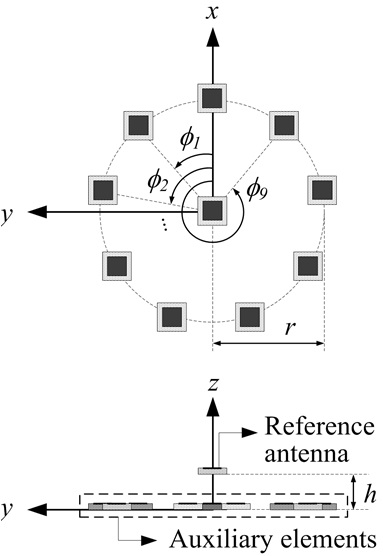
    Fig. 3 shows the proposed array configuration that consists of nine auxiliary elements placed in a circular array and a single reference element at the center. The positions of the auxiliary element are determined by the array radius (r) and the angular positions (ϕ1, ϕ2, ⋯, and ϕ9). The vertical position of the center element is adjusted by parameter h. This vertical placement is important to enhance the resolution of the array pattern at low elevation angles, and it results in better null steering performan cethan the planar arrangement.

    Table 2 presents the optimized values of the proposed array configuration. The array has a large array aperture with an interelement spacing of about 105 mm, and the center element is placed at h = 55.9 mm above the auxiliary elements. To verify the suitability of this configuration, its null steering performance is compared in the next section with two different arrays that have the same number of elements and the same aperture size.

    [Table 2.] Parameters of the proposed array element

    label

    Parameters of the proposed array element

    III. PERFORMANCE EVALUATION

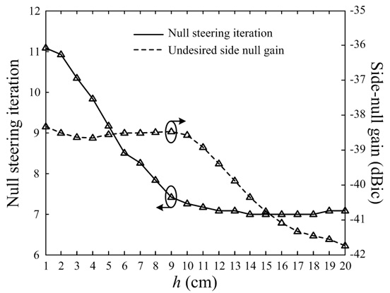
    Fig. 4 demonstrates the effectiveness of placing the center reference antenna above the auxiliary antennas using the parameter h. The θ-direction patterns presented in the figure are obtained after the null steering iterations for an interference source located at θ = 85° and ϕ = 150°. The solid line indicates a θ-direction pattern at ϕ = 150° of the proposed array (h = 55.9 mm), and the dotted line shows that of a planar arrangement (h = 0 mm) having the same antenna positions. Although both array configurations form side nulls at around θ = ±30°, the gain reduction can be significantly improved by applying the height difference. For example, the value is improved from –23.8 dBic to –4.6 dBic at θ = 30° for the proposed configuration.

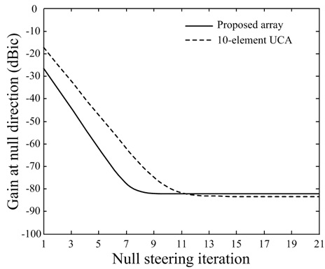
    Fig. 5 presents the comparison of gain variations in the direction of interference according to the null steering iterations between the proposed array and a 10-element uniform circular array (UCA). The solid line illustrates the variation of array gains in the interference direction for the proposed array configuration, and the dashed line presents the variation of the UCA. We can verify that the null steering time can be more effectively reduced by placing the reference element at the center; for example, the array gain at the interference direction decreases by 15.5 dB compared with the UCA in the seventh iteration. In addition, the proposed array requires only 7 iterations to achieve a null direction gain of –80 dBic, whereas the UCA takes 11 iterations. This improvement becomes more significant in mobile environments, e.g., aircraft and missiles, because these applications require the processing time of less than tens of microseconds.

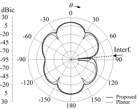
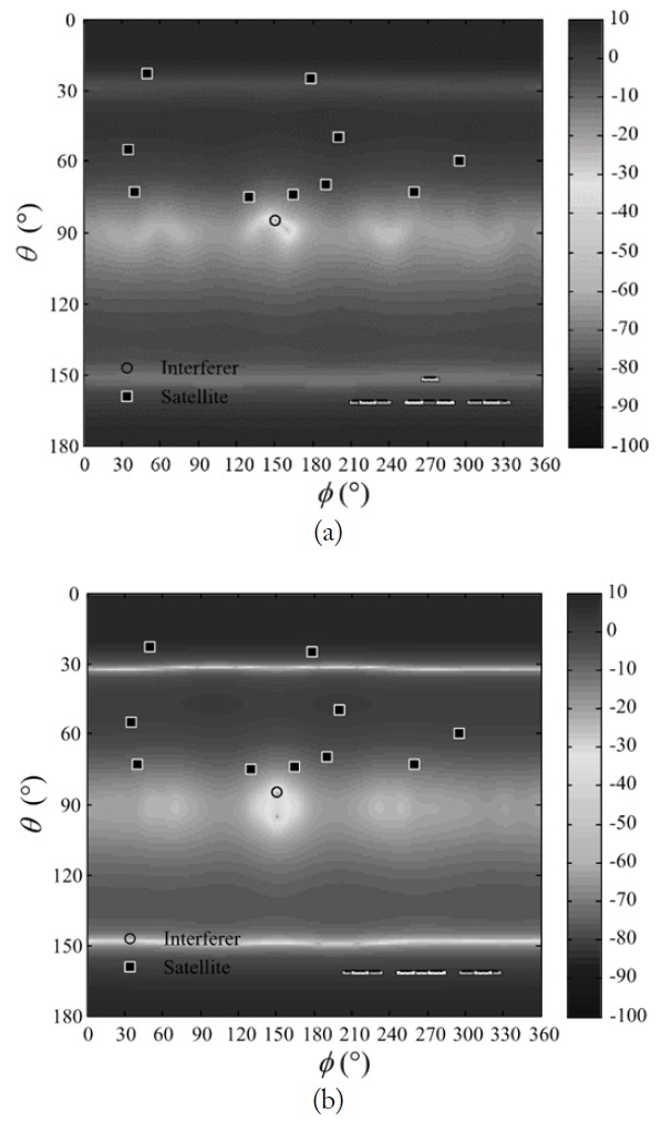
    Another advantage of using the proposed array can be found in Fig. 6, which shows the comparison of the array patterns after the null steering process for an interference source placed at θ = 85° and ϕ = 150°. As illustrated in Fig. 6(a), the proposed array does not have serious side nulls in the upper array pattern. However, the gain at around θ = 30° significantly decreases from –22.3 dBic to –60.2 dBic because of the planar arrangement (h = 0 mm) as presented in Fig. 6(b). The vertical placement of the center element is related to the aperture size in the z-direction, and thus it helps to improve the side-null gain in θ-direction. This improvement is also observed for different directions of the interference sources, and it guarantees that the system is capable of receiving satellite signals without a significant power reduction.

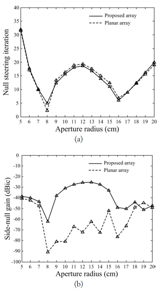
    The proposed array configuration is then evaluated by varying the aperture radius from 5 cm to 20 cm as shown in Fig. 7(a) and (b). The solid line indicates the proposed array configuration, and the dashed line presents the planar arrangement used in Fig. 6(b). Both configurations show a similar trend for the null steering time, but they differ from each other in the sidenull gain because of the vertical placement. This analysis indicates that the null steering time is dependent on the array radius. Moreover, it supports the results in Fig. 6, which shows the variations of the side nulls according to the vertical placement of the center element. To further examine the importance of this vertical placement, the null steering performances are evaluated by adjusting the values of h from 1 cm to 20 cm at an interval of 1 cm as illustrated in Fig. 8. As the value of h decreases (i.e., the array becomes planar), the null steering time increases while the depth of the side nulls becomes shallower. The vertical placement of the center element should be carefully determined to achieve a fast null steering time and to minimize the undesired effect of the side nulls because of this trade-off.

    IV. CONCLUSION

    We investigated an optimum array configuration to improve the null steering time for CRPA systems. The proposed array was composed of nine auxiliary elements arranged in a circular array and a single reference element, and its design parameters, such as the array radius and the vertical placement, were optimized by the GA. The null steering time and the side-null gain of the optimized array were then calculated in conjunction with the constrained LMS algorithm for evaluation. We verified that the reduced null steering time was suitable for fast interference mitigation and that the side-null gains could be increased by about 37.9 dB with the optimized vertical placement. This finding demonstrates that the proposed array is suitable for use in a mobile environment to achieve fast interference suppression without significant side nulls in satellite directions.

참고문헌
  • 1. Ko C. C. 1991 "A fast null steering algorithm for linearly constrained adaptive arrays," [IEEE Transactions on Antennas and Propagation] Vol.39 P.1098-1104 google cross ref
  • 2. Smith S. T. 1999 "Optimum phase-only adaptive nulling," [IEEE Transactions on Signal Processing] Vol.47 P.1835-1843 google cross ref
  • 3. Haupt R. L. 1997 "Phase-only adaptive nulling with a genetic algorithm," [IEEE Transactions on Antennas and Propagation] Vol.45 P.1009-1015 google cross ref
  • 4. Fante R., Vaccaro J. J. 2000 "Wideband cancellation of interference in a GPS receive array," [IEEE Transactions on Aerospace and Electronic Systems] Vol.36 P.549-564 google cross ref
  • 5. Zhang Y., Amin M. G. 2001 "Array processing for nonstationary interference suppression in DS/SS communications using subspace projection techniques," [IEEE Transactions on Signal Processing] Vol.49 P.3005-3014 google cross ref
  • 6. Amin M. G., Zhao L., Lindsey A. R. 2004 "Subspace array processing for the suppression of FM jamming in GPS receivers," [IEEE Transactions on Aerospace and Electronic Systems] Vol.40 P.80-92 google cross ref
  • 7. 2015 "Ceramic patch antenna model: B25-2D02753-STD70," google
  • 8. Frost O. L. 1972 "An algorithm for linearly constrained adaptive array processing," [Proceedings of the IEEE] Vol.60 P.926-935 google cross ref
  • 9. Borre K., Akos D. M., Bertelsen N., Rinder P., Jensen S. H. 2007 A Software-Defined GPS and Galileo Receiver. google
  • 10. Byun G., Choo H., Ling H. 2013 "Optimum placement of DF antenna elements for accurate DOA estimation in a harsh platform environment," [IEEE Transactions on Antennas and Propagation] Vol.61 P.4783-4791 google cross ref
  • 11. Rahmat-Samii Y., Michielssen E. 1999 Electromagnetic Optimization by Genetic Algorithms. google
  • 12. 2015 EM Software and Systems, "FEKO Suite 7.0," google
OAK XML 통계
이미지 / 테이블
  • [ ] 
  • [ Fig. 1. ]  Optimization process for reduced null steering time.
    Optimization process for reduced null steering time.
  • [ Fig. 2. ]  Geometry of an array element. (a) Design parameters and (b) radiation patterns.
    Geometry of an array element. (a) Design parameters and (b) radiation patterns.
  • [ Table 1. ]  Parameters of the array element
    Parameters of the array element
  • [ Fig. 3. ]  Proposed array configuration.
    Proposed array configuration.
  • [ Table 2. ]  Parameters of the proposed array element
    Parameters of the proposed array element
  • [ Fig. 4. ]  θ-direction gain at ? = 150?.
    θ-direction gain at ? = 150?.
  • [ Fig. 5. ]  Null direction gain vs. LMS nulling iterations.
    Null direction gain vs. LMS nulling iterations.
  • [ Fig. 6. ]  Comparison of the array patterns after interference suppression. (a) Proposed array configuration and (b) planar array configuration.
    Comparison of the array patterns after interference suppression. (a) Proposed array configuration and (b) planar array configuration.
  • [ Fig. 7. ]  Effect of the array radius r. (a) Variations of null steering time and (b) variations of side-null gains.
    Effect of the array radius r. (a) Variations of null steering time and (b) variations of side-null gains.
  • [ Fig. 8. ]  Effect of the parameter h.
    Effect of the parameter h.
(우)06579 서울시 서초구 반포대로 201(반포동)
Tel. 02-537-6389 | Fax. 02-590-0571 | 문의 : oak2014@korea.kr
Copyright(c) National Library of Korea. All rights reserved.