Four-conductor lines are widely used in power electronics, such as three-phase power supply circuits. The signals on the multi-conductor lines are conventionally divided into differrential-and common-mode signals, which are used to measure the signal transmission performance of the established circuit. Conventional mixed-mode S-parameters are commonly used to interpret the characteristics of the existing mode signals [1]. The conventional mixed-mode S-parameters include the differential-mode S-parameters, common-mode S-parameters and differrential-common cross-mode S-parameters. The differential-common cross-mode S-parameters are induced due to the asymmetry of the signal lines.
The four-conductor lines model used in this paper has three modes: differential-mode-1 (DM1), differential-mode-2 (DM2) and common-mode (CM) [2]. In [2], extended mixed-mode S-parameters are proposed to characterize the three mode signals of four-conductor lines. The extended mixed-mode S-parameters are estimated from the equivalent independent mode transmission line parameters, which are obtained based on the mode analysis with current division factors [2]. Compared with the conventional mixed-mode S-parameters, there are no cross-mode S-parameters existing in the proposed extended mixe-dmode S-parameters, regardless of whether the four- conductor lines are symmetrical or asymmetrical.
In this paper, extended mixed-mode S-parameters are further applied to a cascaded four-conductor lines model. In general, the two parts of the cascaded four-conductor lines have different current division factors. In other words, the cascaded four-conductor lines are imbalanced. However, these different current division factors will induce cross-mode S-parameters in the extended mixed-mode S-parameters, which are different from the extended mixed-mode S-parameters of four-conductor lines. We note that, unlike the conventional mixed-mode S-parameters in which the cross-mode S-parameters occur due to the asymmetry of the conductor lines, the cross-mode S-parameters of the cascaded four-conductor lines occur due to the different current division factors of the cascaded two parts. In the following sections, this paper will introduce extended mixed- mode S-parameters of the cascaded four-conductor lines based on mode analysis in detail.
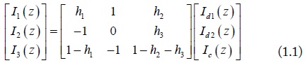
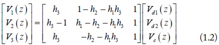
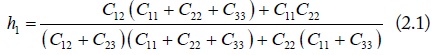
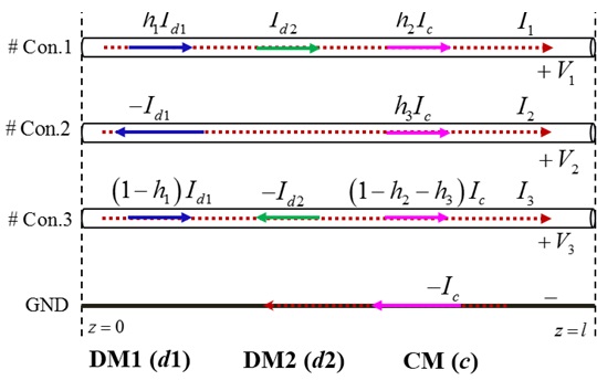
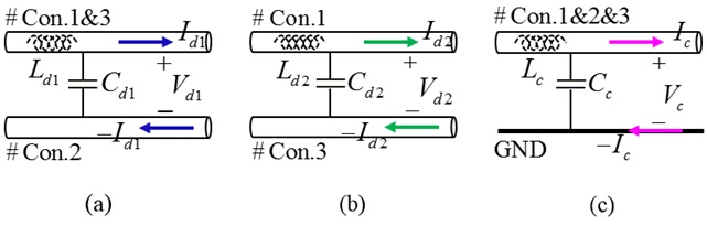
Shown in Fig. 1, a general structure of four-conductor lines is composed of three signal conductors and one ground conductor. The currents on the signal conductors can be decomposed into three mode currents: DM1 (d1), DM2 (d2) and CM (c) [2]. As shown in Fig. 1, a current division factor h1 is used to divide the same direction currents of DM1. And the other two current division factors h2 and h3 are used for the currents of CM. With the current division factors, the mode transformations of the voltage and current on the four-conductor lines are given by the following collections:
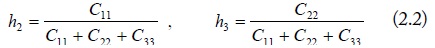
For the lossless lines, the current division factors can be decided by the line capacitances [2].
where, Cii and Cij are the self- and mutual-capacitances of the four-conductor lines. For the symmetrical four-conductor lines, the above current division factors become: h1 = 1⁄2, and h2 = h3 = 1⁄3.
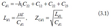
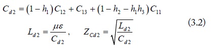
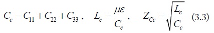
The line voltage and current of the four-conductor lines, as is well known, satisfy the equations from the per-unit-length line inductances and capacitances [3]. We take the equations of mode transformation in Eq. (1) and the expression of current division factors in Eq. (2) into the line voltage and current equations, each mode can be considered as an independent two-conductor lines with the equivalent mode capacitance, inductance and characteristic impedance. They are obtained as:
where, μ and ε are the effective permeability and permittivity of the four-conductor lines, respectively. They can be estimated through the inductances and capacitances of the four-conductor lines, i.e. LC = μεI.
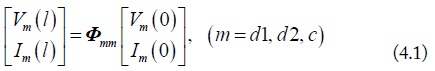
With the above mode transmission line parameters, the terminal voltage and current of each mode can be related through the mode chain-parameters shown in the following.
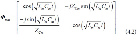
where, the general expression of chain-parameters for two-conductor lines is shown as:
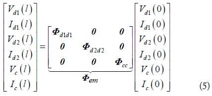
Extended mixed-mode chain-parameters of four-conductor lines can be decided by collecting each mode chain-parameters. The collection is shown as follows.
As shown in the equation, the extended mixed-mode chain-parameters do not contain the cross-mode chain-parameters, due to the separate mode transmission line parameters. Therefore, each mode chain-parameters are independent from the others, and can be converted to the corresponding mode S-parameters.
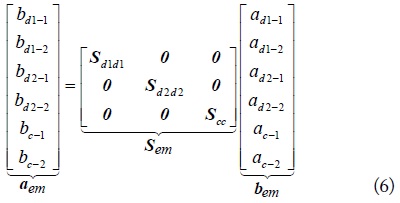
The extended mixed-mode S-parameters of the four-conductor lines are generated by combining each mode S-parameters, are given in Eq. (6) below [2].
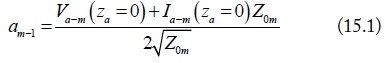
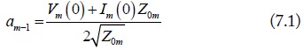
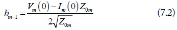
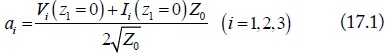
where, am-i and bm-i, as shown in Fig. 3, are the normalized port waves of the m (m = d1, d2, c) mode equivalent circuits. They are normalized by the port terminal voltage, current, and port reference impedance. For port-1 of the m mode, the normalizations are:
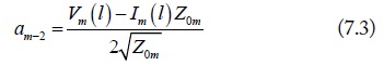
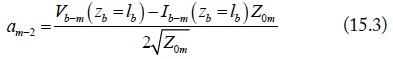
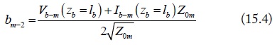
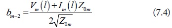
Due to the current direction, the definitions of m mode at port-2 are:
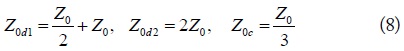
In the above equations, Z0m is the port reference impedance. Based on the mode analysis in Fig. 1, the port reference impedances are equal to
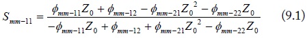
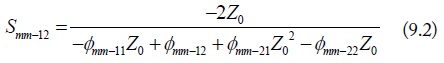
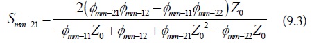
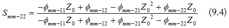
and the conversion from the mode chain-parameters to the mode S-parameters can be derived by plugging Eq. (7) into Eq. (5):
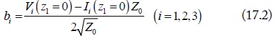
where, Z0 is the port reference impedance, commonly Z0 =50 Ω.
As shown in Eq. (6), the new extended mixed-mode S-parameters do not contain the cross-mode S-parameters, the same with the extended mixed-mode chain-parameters. The new extended mixed-mode S-parameters are completely different from the conventional mixed-mode S-parameters in [1]. In the conventional mixed-mode S-parameters, the cross-mode parameters will be induced when the conductors are asymmetrical. In the following section, the extended mixed-mode S-parameters for the cascaded four-conductor lines are further described in detail.
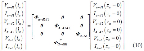
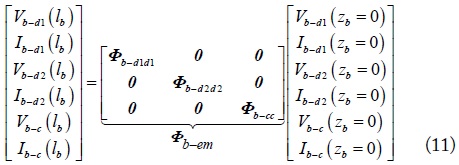
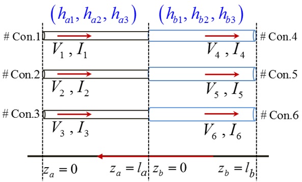
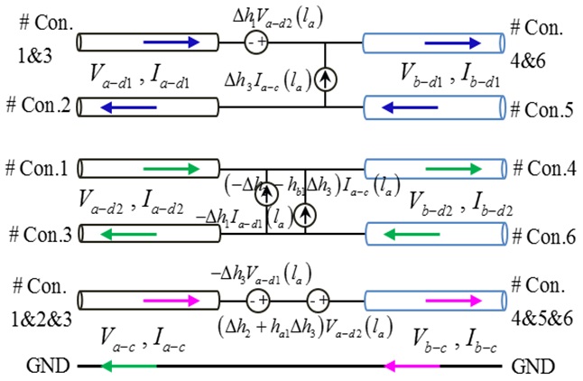
General cascaded four-conductor lines, in which the cascaded two parts have different current division factors, are shown in Fig. 4. The line voltage and current are continuous on the cascaded four-conductor lines. The mode voltage and current, however, are discontinuous due to the different current division factors. As shown in Fig. 5, the equivalent mode conductors of the cascaded two parts can be obtained by processes similar to those described in Section II. Then, the extended mixed-mode chain-parameters of the connected equivalent mode conductors are given as:
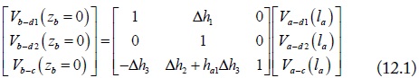
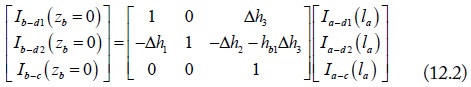
In addition, note that the mode conversion occurs at the connection of the two equivalent mode circuits. The voltage or current sources from the mode conversion are induced at the connection points [4]. The mode conversions at za = la (zb = 0) are expressed as:
where, Δh is the difference of the current division factors, i.e., Δhi = hbi - hai, (i = 1,2,3). For the balanced cascaded four-conductor lines, (i.e., Δhi = 0), the above voltage and current conversion matrices become the unit matrix.
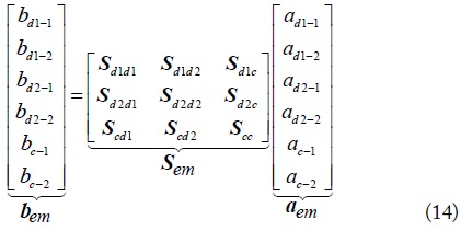
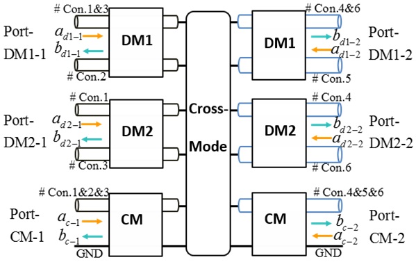
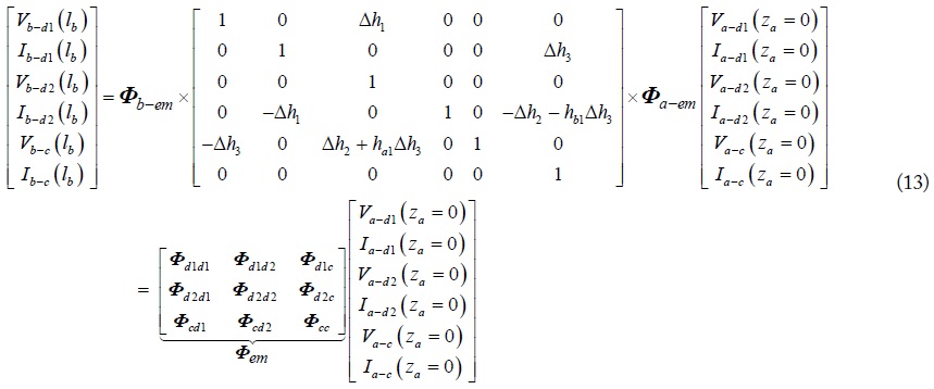
Combining the extended mixed-mode chain-parameters in Eq. (10), Eq. (11) and the mode conversion equations in Eq. (12), the extended mixed-mode chain-parameters of the equivalentmode circuits in Fig. 5, which are the multiplication of each connected part, are denoted as in Eq. (13). It is worth noting that the cross-mode chain-parameters are induced due to the imbalanced current division factors of the cascaded two four-conductor lines. The extended mixed-mode S-parametersof the cascaded four-conductor lines can also be transformed from the extended mixed-mode chain-parameters. The transformation between the extended mixed-mode chain-parameters and S-parameters, however, cannot be done as in Eq. (9), where that the extended chain-parameters were separated into three independent two-port mode chain-parameters. That is because each mode parameters in Eq. (13) are associated with each other by the cross-mode parameters. Because of the space limitation, the transformation between them is not shown in here. It can be performed by emulating the method of two-port transformation in Eq. (9). The ports of each mode are denoted in Fig. 6, and the definition of the extended mixed-mode S-parameters is shown as follows.

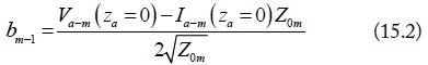
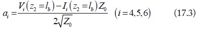
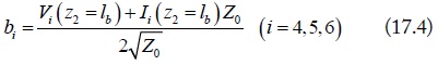
Similarity, am-i and bm-i are the mode normalized port waves. Their normalizations are:
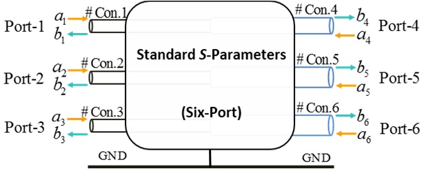
The extended mixed-mode S-parameters shown in Eq. (14) are composed of the self-mode S-parameters and the cross-mode S-parameters. The self-mode S- parameters describe the mode current flowing on the cascaded four-conductor lines, while the cross-mode S-parameters are used to describe the mode conversions occurring at the connection of the cascaded structures. Besides, the cascaded four-conductor lines shown in Fig. 4 can also be labelled with the normalized standard port waves, shown in Fig. 7. Then, the six-port standard S-parameters are induced to present the signal transmission on the cascaded four-conductor lines. The mode conversion between the standard S-parameters and the extended mixed-mode S-parameters is derived in the following section.
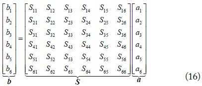
The six-port standard S-parameters of the cascaded four-conductor lines are defined as:
In the equation, ai and bi are the normalized standard waves at port i (i = 1, 2, …, 6). Their definitions are:
In order to obtain the mode conversion between the extended mixed-mode S-parameters and the standard S-parameters, we substitute the voltages and current mode transformation in Eq. (1) into the definition equations of port waves in Eq. (15) and Eq. (17). Then, a conversion between the normalized standard port waves (ai, bi) and the mode port waves (am-i, bm-i) is obtained as:
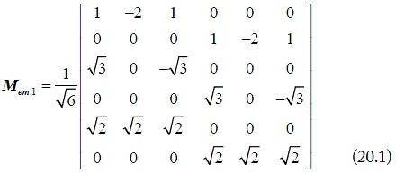
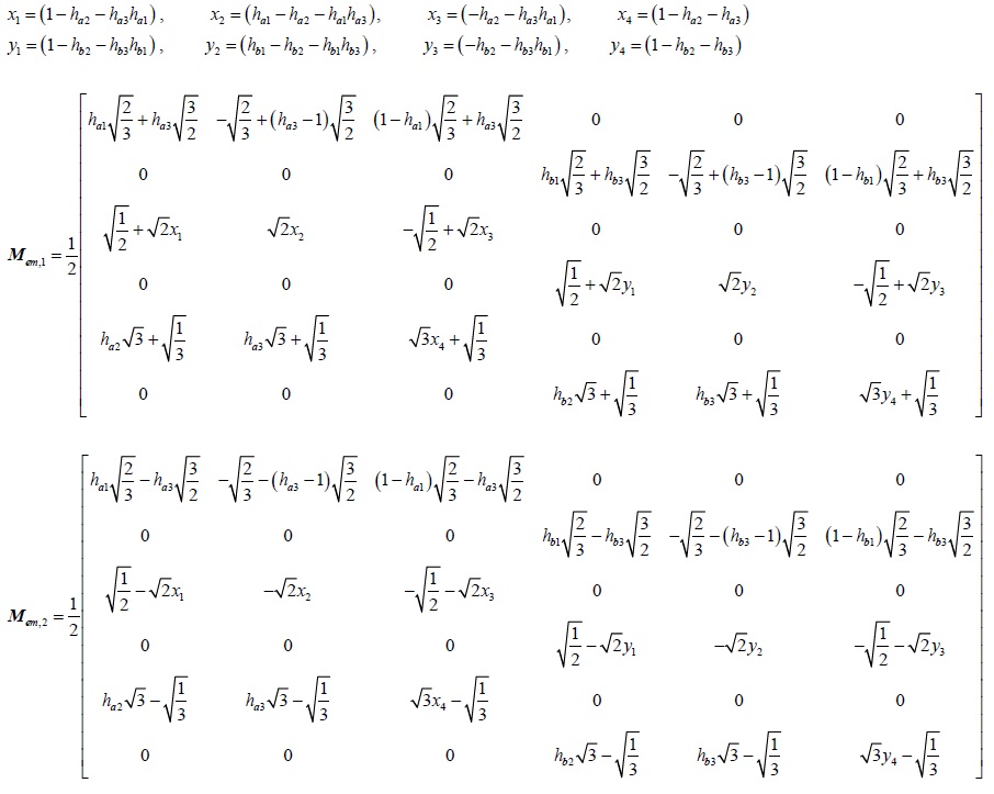
where, Mem,1 and Mem,2 are the new mode conversion matrices shown below. Compared to the mode conversion matrix in [5], the new conversion matrices proposed in Eq.(18) contain the different current division factors, which consider the divided mode current on the asymmetrical signal lines.
Finally, given Eq.(14), Eq.(16), and Eq.(18), the conversion between the extended mixed-mode S-parameters and the standard S-parameters is:
Moreover, if both of the cascaded two four-conductor lines are symmetrical (i.e. ha1 = hb1 = 1/2 and ha2 = ha3 = hb2 = hb3 = 1/3), the mode conversion matrices listed above become:
Then, the mode conversion in Eq.(19) simplifies to:
With the above mode conversion, the extended mixed-mode S-parameters can also be directly converted from standard S-parametersusing the current division factors. To confirm the validity of the new proposal in this paper, the estimated standard S-parameters and extended mixed-mode S-parameters of the shielded cable, used as an example of cascaded four-conductor lines, were compared with the simulated results.
IV. VERICATION OF THE EXTENDED MIXED-MODE S-PARAMETERS FOR THE CASCADED FOUR-CONDCUTOR LINES
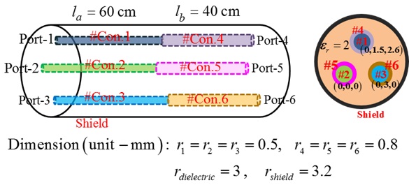
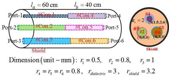
A shielded cable is shown in Fig. 8, in which three cascaded inner conductors are used as the signal lines and the outside shield is the ground. In this model, the inner conductors and the outside shield are perfect conductors. A dielectric material with a permittivity of 2 is fills in the shield. The cascaded two parts are simulated by Ansoft Q3D to separately estimate the inductances and capacitances. As shown in Fig. 8, the radius of the cascaded signal lines, though of different sizes, are all symmetrical with the outside shield. The current division factors of the two cascade two parts are balanced. They are: ha1 = hb1 = 1/2 and ha2 = ha3 = hb2 = hb3 = 1/3. Therefore, there are no cross-mode S-parameters in the extended mixed-mode S-parameters of the shielded cable.
By using the simulated inductances and capacitances, the extended mixed-mode S-parameters of the shielded cable were first estimated by following the above processes. The extended mixed-mode S-parameters can also be simulated by 3D EM software (CST Microwave Studio) in the frequency range of 1 GHz to 10 GHz.
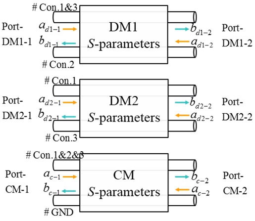
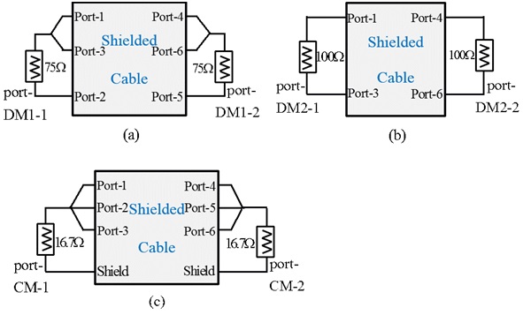
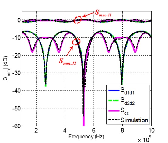
Based on the mode analysis of four-conductor lines, the simulation schematics of each mode S-parameters, composing the extended mixed-mode S-parameters, are shown in Fig. 9. Note that because there are no cross-mode S-parameters, each mode S-parameters are independent and can be simulated separately. The simulated and estimated extended mixed-mode S-parameters are compared in Fig. 10.

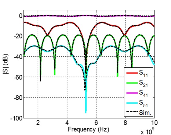
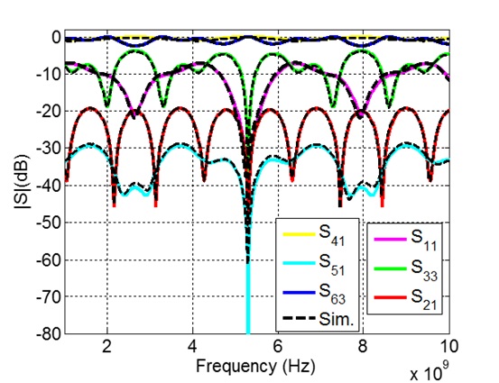
Fig. 10 shows a good consistency between the estimated and simulated results, which verified the validity of the proposed extended mixed-mode S-parameters. Moreover, as shown in Fig. 10, the S-parameters of DM1 are the same as the S-parameters of DM2. That is due to the symmetrical signal lines of the shielded cable. For the symmetrical four-conductor lines, the characteristic impedances of DM1 and DM2 in Eq. (3) have a relationship that: ZCd2 = (4/3) ZCd1. And the mode port reference impedances in Eq.(8) have the same relationship, i.e., Z0d2 = (4/3)Z0d1. Besides, the standard S-parameters of the shielded cable were also simulated by the Microwave Studio and were also estimated by the simplified conversion equation in Eq. (21). The good match shown in Fig. 11 confirmed the validity of the mode conversions between the extended mixed-mode S-parameters and the standard S-parameters.
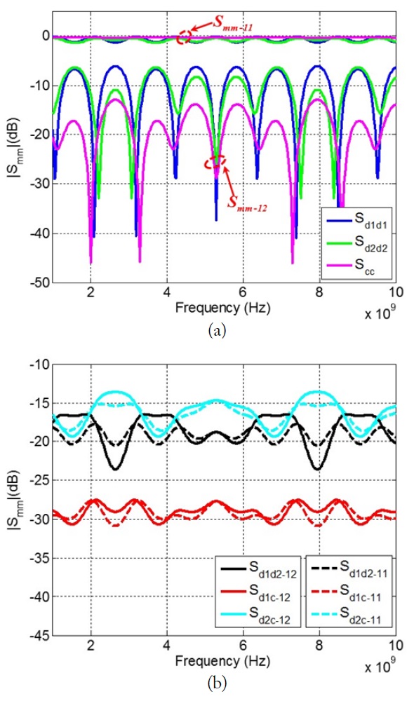
Furthermore, a shielded cable with imbalanced current division factors was also analyzed. As shown in Fig. 12, the signal lines in the second part of the shielded cable are still symmetrical, but the signal lines in the first part change to asymmetrical. With the simulated inductances and capacitances, the current division factors of the first part become: ha1 = 0.2838, ha2 = 0.182 and ha3 = 0.3156. Therefore, the cross-mode S-parameters were induced due to the imbalanced current division factors. It is worth noting that the self-mode S-parameters of the imbalanced shielded cable cannot be simulated by the schematics in Fig. 9. That is because the self-mode S-parameters are not independent of each other, due to the existence of the cross-mode S-parameters. Therefore, only the estimated extended mixed-mode S-parameters of the shielded cable are just shown in Fig. 13. Unlike the self-mode S-parameters of the balanced shielded cable in Fig. 10, the self-mode S-parametersshown in Fig. 12(a) are completely different due to the asymmetrical parts in the shielded cable. And, as shown in Fig. 12(b), the mode conversion occurring between DM1 and CM is the lowest. Finally, the standard S-parameters of the imbalanced shielded cable were estimated and compared with the simulated results in Fig. 14. The completely identical results, once again, confirmed the effectiveness of the proposed extended mixed-mode S-parameters and the mode conversion for the cascaded four-conductor lines.
This paper proposed the novel extended mixed-mode S-parameters of cascaded four-conductor lines, based on the independent mode analysis of the general four-conductor lines with current division factors. Compared to the extended mixed-mode S-parameters of four-conductor lines, the cross-mode S-parameters are generated by the different current division factors of the cascaded two four-conductor lines. In addition, two new conversion matrices, containing the different current division factors, were also proposed in this paper. The validity of the extended mixed-mode S-parameters and the conversion matriceswas verified by a comparison of the estimated and simulated results of a balanced shielded cable and an imbalanced shielded cable.