검색 전체 메뉴
PDF
맨 위로
OA 학술지
A Low-Profile Dipole Array Antenna with Monopole-Like Radiation for On-Body Communications
  • 비영리 CC BY-NC
  • 비영리 CC BY-NC
ABSTRACT
A Low-Profile Dipole Array Antenna with Monopole-Like Radiation for On-Body Communications
KEYWORD
Low Profile , On-Body Antenna , Monopole-Like Radiation , Wireless Body Area Network (WBAN)
  • I. INTRODUCTION

    Wireless body area network (WBAN) has recently received great attention due to its applicability in various services. Depending on the location of the transceiver on the human body, a WBAN system can be categorized as off-body, on-body, or inbody [1]. The radiation characteristics of an antenna for a WBAN system are particularly important in establishing a successful communications link between the transceivers. In order to establish a good on-body communication channel between two on-body devices, an antenna is required to have radiation characteristics similar to those of a vertical monopole antenna. However, a monopole antenna is not suitable for on-body communications, due to its large vertical size. Therefore, a lowprofile antenna with monopole-like radiation characteristics is necessary for on-body communication. In order to obtain a lowprofile antenna with a monopole-like radiation pattern, various types of antennas have been proposed [2-10]. Dielectric resonator antenna types for monopole-like radiation characteri-stics were published in [2, 3]; however, the vertical size of those antennas is too large for use in on-body devices. In [4], an Alford loop antenna for surface-wave generation was proposed, but the Alford loop antenna is not suitable for on-body communications because its performance is substantially affected by the human body environment.

    In order to realize a low-profile antenna with a monopolelike radiation pattern, several types of patch antennas using various resonance modes have been proposed [5-10]. In [5], a microstrip monopolar patch antenna using TM01 and TM02 resonance modes for monopole-like radiation characteristics was suggested. A circular patch-ring antenna with TM02 mode was proposed in [6]. TM01 and TM02 mode antennas have greater gain than higher-order mode (TM21, TM41) antennas. However, the antennas should be large for on-body devices. Rectangular patch antennas using the TM21 mode were introduced in [7, 8]. Generally, the TM21 mode antenna is smaller than TM01, 02, 41 antennas. However, TM01, 02, 41 mode antennas generate a radiation pattern that is closer to omnidirectional compared to that of a TM21 mode antenna. TM41 mode antennas have a higher maximum radiation angle from the zenith than TM21 mode antennas [9, 10].

    In this paper, a low-profile dipole array antenna with a monopole-like radiation pattern for on-body communications is proposed. The antenna operates in the 2.45 GHz industrial, scientific, and medical (ISM) band with omnidirectional radiation characteristics. The performance of the proposed antenna is verified both numerically and experimentally when it is attached to a two-thirds muscle-equivalent semi-solid phantom.

    Ⅱ. ANTENNA DESIGN

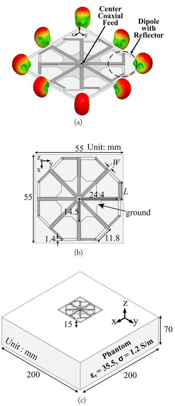
    Fig. 1(a) and (b) show the structure of the dipole array antenna. The proposed antenna, with dimensions of 55 mm × 55 mm × 1.6 mm (0.44 λ0 × 0.44 λ0 × 0.013 λ0 at 2.45 GHz), is designed on a FR-4 (εr = 4.4, tanδ = 0.0245) substrate. Each dipole element with a ground, shown in Fig. 1(a), has a directional radiation pattern toward the horizontal direction, since the ground acts as a reflector. The proposed antenna consists of eight directional dipoles with a ground. As eight dipole elements are placed symmetrically around the z-axis, the proposed antenna generates a monopole-like radiation pattern with a low profile. The antenna is excited by a center coaxial feed. The width of the dipole element is 1.4 mm and the length of the dipole element is 11.8 mm. To reduce the human body effect, the ground is installed on the bottom plane. To analyze the performance of the antenna numerically, a two-thirds muscleequivalent phantom (εr = 35.5, σ = 1.2 S/m) with dimensions of 200 mm × 200 mm × 70 mm was designed as depicted in Fig. 1(c) [11]. The proposed antenna was located 15 mm from the phantom surface, considering the height of a wearable device.

    III. PARAMETRIC STUDY

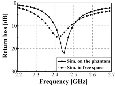
    Fig. 2 shows the comparison between the simulated return loss characteristics of the proposed antenna in free space and on the phantom. Due to the human body effect, the resonance frequency shifts slightly to the higher frequency side, and the bandwidth is decreased. The 10-dB return loss bandwidth was 4.1% (2.39–2.49 GHz) in the 2.45 GHz ISM band (2.4–2.485 GHz).

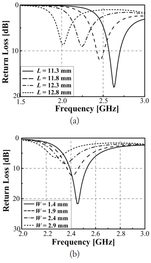
    Fig. 3(a) and (b) show the simulated return loss characteristics for various design parameters. As the dipole length L or the feed line width W decreases, the resonant frequency shifts slightly to the high-frequency side and the impedance matching is improved, as shown in Fig. 3(a) and (b).

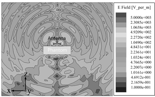
    Fig. 4 shows the simulated electric field magnitude distribution of the antenna on the phantom in the xz-plane at 2.45 GHz. The proposed antenna is suitable for on-body communications due to the similarity of its radiation pattern to that of a vertical monopole antenna.

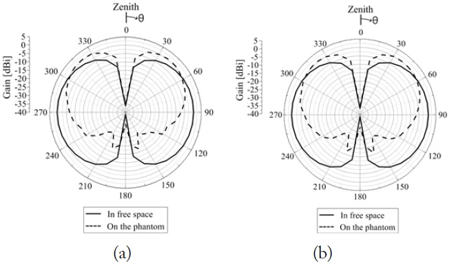
    Fig. 5(a) and (b) show the simulated far-field radiation patterns of the proposed antenna in free space and those of the phantom at 2.45 GHz in the xz-plane and in the yz-plane, respectively. The minimum radiation of the proposed antenna is at θ = 0° and the maximum radiation is at θ = 50°. The simulated realized peak gains of the proposed antenna in free space and on the phantom are 0.5 dBi and 0.8 dBi, respectively. Due to the reflection from the phantom, the peak gain of the proposed antenna on the phantom is higher than the peak gain in free space. The total radiation efficiencies of the proposed antenna without and with the phantom are 84.3% and 34.06%, respectively. The simulation results of this work were obtained by High Frequency Structure Simulator (HFSS) v.14.0.0 (ANSYS Inc., Canonsburg, PA, USA).

    Ⅳ. MEASURED RESULTS

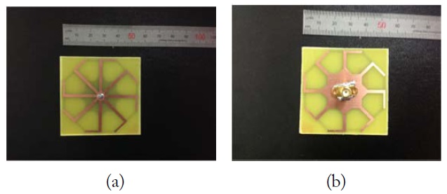
    Fig. 6 shows the top and bottom view of the manufactured antenna. The antenna was fabricated on a FR-4 (εr = 4.4, tanδ = 0.0245) substrate 1.6 mm in thickness.

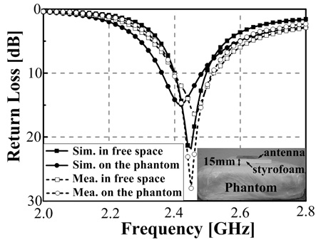
    Fig. 7 shows the simulated and measured return loss cha-racteristics of the proposed antenna. To analyze the antenna performance experimentally, a two-thirds muscle-equivalent semi-solid phantom (εr = 35.5, σ = 1.2 S/m) with dimensions of 200 mm × 200 mm × 70 mm was used. The measured result agrees well with the simulation. From the measurement, the 10-dB return loss bandwidth is 120 MHz (4.9%), ranging from 2.4 to 2.52 GHz, which is wide enough to cover the entire 2.45 GHz ISM band (2.4–2.485 GHz).

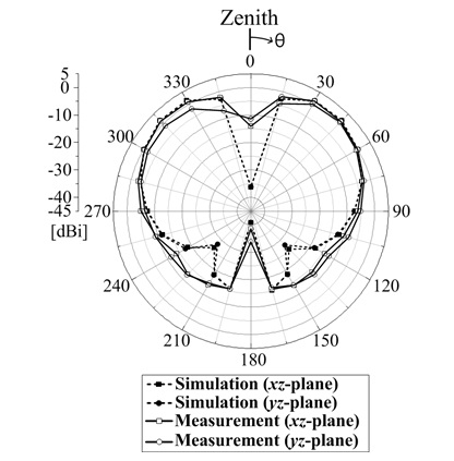
    Fig. 8 shows the simulated and measured far-field radiation patterns of the proposed antenna on the phantom at 2.45 GHz in the E-plane and the H-plane. The measurement results agree reasonably well with the simulation. The minimum radiation of the fabricated antenna is in the direction normal to the phantom surface (zenith direction), and the maximum radiation is at θ = 50°. The measured peak gain of the proposed antenna on the phantom in the E- and H-planes is 0.4 dBi.

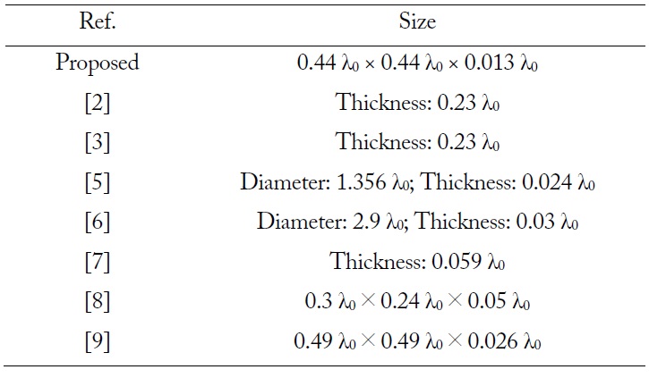
    Table 1 shows the comparison of the size of the proposed antenna and those of the reference antennas with monopolelike radiation. It is observed that the proposed antenna is well designed for its compact size.

    [Table 1.] Comparison between the size of the proposed antenna and those of the reference antennas with monopole-like radiation

    label

    Comparison between the size of the proposed antenna and those of the reference antennas with monopole-like radiation

    Ⅴ. CONCLUSION

    In this paper, a low-profile dipole array antenna with a monopole-like radiation pattern for WBAN on-body communications applications is proposed. The bandwidth of the proposed antenna can cover the 2.45 GHz ISM band (2.4–2.485 GHz) fully while maintaining a low-profile configuration with a height of only 0.013 λ0 at 2.45 GHz. To obtain a monopolelike radiation pattern with a low profile, eight dipole elements were placed symmetrically around the z-axis. Moreover, the measured results show that the proposed antenna generates monopole-like radiation characteristics with a compact size. The proposed antenna has a maximum radiation angle (measured from the zenith) greater than those reported in [6, 7]. Therefore, the proposed antenna is a promising candidate for on-body communications devices.

참고문헌
  • 1. Hall P. S., Hao Y. 2006 Antennas and Propagation for BodyCentric Wireless Communications. google
  • 2. Guha D., Antar Y. M. 2006 "New half-hemispherical dielectric resonator antenna for broadband monopole-type radiation," [IEEE Transactions on Antennas and Propagation] Vol.54 P.3621-3628 google cross ref
  • 3. Guha D., Gupta B., Kumar C., Antar Y. M. 2012 "Segmented hemispherical DRA: new geometry characterized and investigated in multi-element composite forms for wideband antenna applications," [IEEE Transactions on Antennas and Propagation] Vol.60 P.1605-1610 google cross ref
  • 4. Chuang H. R., Horng T. S., Pan J. W., Wang C. H. 1998 "Omni-directional horizontally polarized Alford loop strip antenna," google
  • 5. Liu J., Xue Q., Wong H., Lai H., Long Y. 2013 "Design and analysis of a low-profile and broadband microstrip monopolar patch antenna," [IEEE Transactions on Antennas and Propagation] Vol.61 P.11-18 google cross ref
  • 6. Al-Zoubi A., Yang F., Kishk A. 2009 "A broadband centerfed circular patch-ring antenna with a monopole like radiation pattern," [IEEE Transactions on Antennas and Propagation] Vol.57 P.789-792 google cross ref
  • 7. Delaveaud C., Leveque P., Jecko B. 1994 "New kind of microstrip antenna: the monopolar wire-patch antenna," [Electronics Letters] Vol.30 P.1-2 google cross ref
  • 8. Conway G. A., Scanlon W. G. 2009 "Antennas for overbody-surface communication at 2.45 GHz," [IEEE Transactions on Antennas and Propagation] Vol.57 P.844-855 google cross ref
  • 9. Tak J., Choi J. 2014 "Circular-ring patch antenna with higher order mode for on-body communications," [Microwave and Optical Technology Letters] Vol.56 P.1543-1547 google cross ref
  • 10. Huang J. 1984 "Circularly polarized conical patterns from circular microstrip antennas," [IEEE Transactions on Antennas and Propagation] Vol.32 P.991-994 google cross ref
  • 11. Gabriel C. 1996 "4-Cole-Cole analysis on compilation of the dielectric properties of body tissues at RF and microwave frequencies," google
OAK XML 통계
이미지 / 테이블
  • [ Fig. 1. ]  Geometry of the proposed antenna. (a) Concept of the antenna. (b) Top view of the antenna. (c) Simulation setup for the antenna on the phantom.
    Geometry of the proposed antenna. (a) Concept of the antenna. (b) Top view of the antenna. (c) Simulation setup for the antenna on the phantom.
  • [ Fig. 2. ]  Comparison between the simulated return loss characteristics of the proposed antenna in free space and on the phantom.
    Comparison between the simulated return loss characteristics of the proposed antenna in free space and on the phantom.
  • [ Fig. 3. ]  Comparison between the simulated return loss characteristics for various design parameters. (a) Variations in length L. (b) Variations in width W.
    Comparison between the simulated return loss characteristics for various design parameters. (a) Variations in length L. (b) Variations in width W.
  • [ Fig. 4. ]  Simulated electric field magnitude distribution at 2.45 GHz.
    Simulated electric field magnitude distribution at 2.45 GHz.
  • [ Fig. 5. ]  Comparison between the simulated far-field radiation patterns of the proposed antenna in free space and on the phantom at 2.45 GHz. (a) xz-plane. (b) yz-plane.
    Comparison between the simulated far-field radiation patterns of the proposed antenna in free space and on the phantom at 2.45 GHz. (a) xz-plane. (b) yz-plane.
  • [ Fig. 6. ]  Photographs of the manufactured antenna. (a) Top view. (b) Bottom view.
    Photographs of the manufactured antenna. (a) Top view. (b) Bottom view.
  • [ Fig. 7. ]  Simulated and measured return loss characteristics of the proposed antenna.
    Simulated and measured return loss characteristics of the proposed antenna.
  • [ Fig. 8. ]  Simulated and measured far-field radiation patterns of the proposed antenna on the phantom at 2.45 GHz.
    Simulated and measured far-field radiation patterns of the proposed antenna on the phantom at 2.45 GHz.
  • [ Table 1. ]  Comparison between the size of the proposed antenna and those of the reference antennas with monopole-like radiation
    Comparison between the size of the proposed antenna and those of the reference antennas with monopole-like radiation
(우)06579 서울시 서초구 반포대로 201(반포동)
Tel. 02-537-6389 | Fax. 02-590-0571 | 문의 : oak2014@korea.kr
Copyright(c) National Library of Korea. All rights reserved.