In special GNSS receiver applications (geodetic, goniometric measurements, and so on) it is very important to mitigate multipath signals. Multipath signal is a signal, received by an antenna not directly, but after some reflections from the ground or from some antenna surrounding constructions. Multipath signals cause phase noise in the GNSS equipment as the trace of the multipath signal is longer than original one’s. Owing to the fact, multipath signal comes to the antenna with the phase, which differs from the phase of the direct signal. Additional phase noise in the receiver increases the coordinate determination error [1]. Mostly multipath signals come from the bottom antenna hemisphere. For multipath mitigating special ground planes are usually used.
Mostly choke ring ground planes are used for multipath mitigating [2-4]. They contain quarter wavelength gaps, which operate as band gap structures. Antenna element is placed in the center of such a ground plane. A deficiency of such const- ructions is their big size and weight. Construction of so called vertical choke ring allows reducing size and weight somehow [5]. But more compact and lower weight construction of multipath mitigating ground plane can be obtained using high impedance structures [6-9], including radial [10], and semitransparent [11]. High impedance ground planes are formed by coupled resonant elements and are frequency selective electromagnetic band gap (EBG) structures. Practical realization of GNSS antennas with EBG ground planes is presented in [12,13].
But all multipath mitigating ground planes (except a vertical choke ring), being as a matter of fact band gap structures in radial direction and radiating structures in vertical direction, have a common deficiency—they spoil the antenna element phase center stability and narrow its radiation pattern. Vertical choke ring, having quarter wavelength gaps on its edges, does not narrow an antenna element radiation pattern, and does not infect antenna element phase center so much, but it cannot provide multipath mitigating in bottom hemisphere more than 25 dB.
In this work a special radial-type EBG metamaterial and special construction of multiband multipath mitigating ground plane made of this material, are presented. It is shown, that implementation of such a ground plane in the GNSS antenna module construction allows achieving a multiband multipath mitigation without spoiling the antenna element radiation pattern and phase center stability unlike other GNSS antenna ground plane constructions [7-13].
II. EBG METAMATERIAL CONSTRUCTION
Since EBG structures were first presented by Sievenpiper et al. [6] they take an interest of many researchers. Theoretical analysis and practical implementation of EBG are well-described in [14]. A small size of EBG elements allows obtaining a compact construction of various frequency selective devises and abundance of element modifications allows widening their working bands [15-17]. Also as it is shown in [18] that EBG constructions have metamaterial properties [19], what gives additional opportunities for design of frequency-selective surfaces.
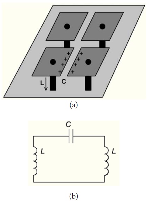
A schema of a mushroom-type EBG structure element is presented on Fig. 1. It consists of conducting square-shaped mushroom heads and conducting vias, which connect mushroom heads to the conducting ground plane. As its top layer meats electromagnetic waves, currents are inducted in the mushroom head. A voltage applied parallel to the top surface makes charges on the mushroom head edges, which can be described as capacitors. Then charges flow along vias to the bottom ground plane. These currents are associated with a magnetic field and vias are associated with an inductance.
The impedance of this surface is assigned to be equal to the impedance of a parallel resonant circuit, considering to the capacitance and inductance [6].
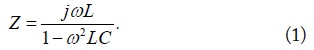
The surface impedance is inductive at low frequencies and capacitive at high frequencies. The impedance is very high near the resonance frequency
Capacitance is determined by the length of two coupled sides of the two neighbor mushrooms, and the inductance is partly determined by the substrate thickness and via diameter and partly with a structure of the mushroom head. The high impedance is associated with a forbidden frequency band gap. The band gap can be obtained from [6]:
where η = 120π.
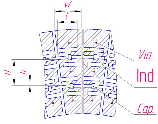
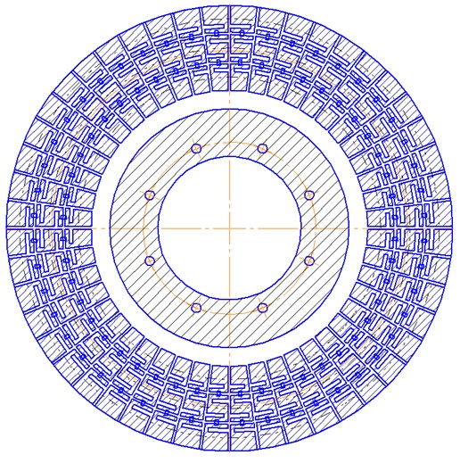
The proposed EBG surface is presented on Fig. 2. As it will be shown further, the structure was designed for a round-shape ground plane to prevent wave propagation from the outer edge to the center, where an antenna element should be mounted.
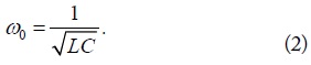
The construction of the mushroom head of the presented here EBG structure differs with a corner-shape distributed inductances, placed on the coupled sides of the mushroom heads which decrease the structure resonance frequency (correspondingly to (2)) and widen the band gap (correspondingly to (3)).
That’s why distributed inductances are placed only on the top and bottom edges of the mushroom head. Also lumped capacitances are placed between the coupled EBG elements. Changing the capacitance of the lumped elements the resonance frequency of the structure can be readjusted in a wide range, as it is seen from the Eq. (2).
The described structure was designed to operate in
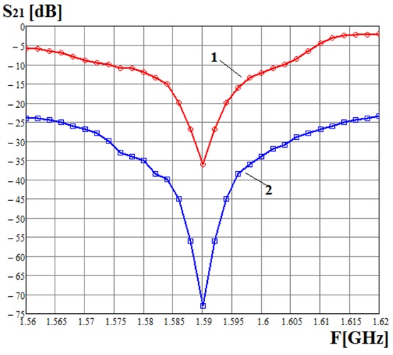
The structure was manufactured using the PSB technology and its
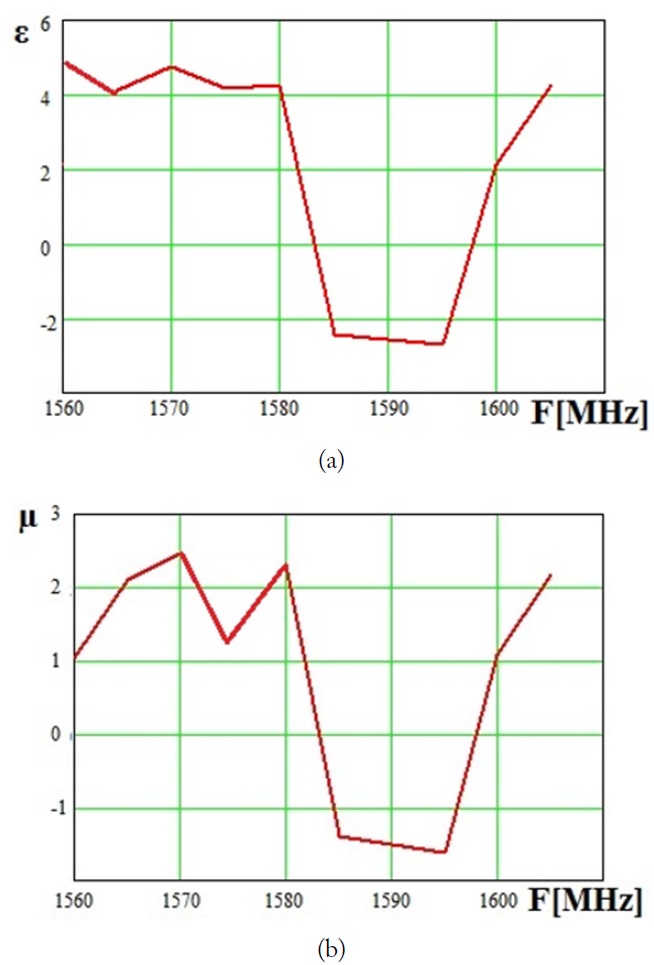
Using measured
It is well seen from the graphs, that the presented EBG structure has negative values of effective permittivity and permeability near the resonant frequency
To adjust the structure for operating in
III. EBG METAMATERIAL APPLICATION
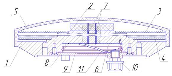
A structure of the EBG metamaterial ground plane is presented on Fig. 6. The ground plane has a disk shape. The EBG elements are concentrically placed around the center of the disk. There is a hole in the disk center, which is used for mounting the ground plane on a base, on which also all other elements of an antenna module are placed, as it is shown on Fig. 7.
The base (‘1’) radius is equal to a half wave length of the maximal frequency in L1 band. The EBG discs (‘3’) are placed on the base stages in such a way that the ground plane of the EBG structure is on the top and ‘mushroom heads’ are on the bottom and disk with a higher resonance frequency is on the top and the disk with the lower resonance frequency is on the bottom (each disk is adjusted by changing the value of lumped capacitors taking in account the influence of the neighbor discs). Resonant gaps (‘4’) shorted by screws on the base stages and open on the outer edges are formed between two neighbor disks and the bottom disc and the base. The gaps are formed by EBG structure of the top disc and the ground plane of the bottom disc. Resonant frequencies of the gap and the EBG structure, which forms it, should be equal. In this construction the number of gaps is also equal to the number of EBG discs and to the number of antenna element resonance frequencies.
A multifrequency antenna element (‘2’) is placed on the top of a pyramid-shape base (‘1’) under a cover (‘5’). A low noise amplifier (‘8’) is placed in a base hollow (‘6’), which is closed by the cover (‘9’) and connected to the antenna element and the UHF connector (‘10’) by the cables (‘7’) and (‘11’). The ground plane of the top EBG disc forms a union conducting plane with a top of the pyramid, making a union antenna element ground plane.
The multipath mitigating ground plane construction, described above, can be viewed as a modification of a vertical choke ring [5], in which one of the gap planes is made in the form of an EBG structure. Such a ground plane construction increases mitigation of signals, which come from the antenna module bottom hemisphere (rejected signals).
The multipath mitigating ground plane in the presented construction is formed by EBG metamaterial disks (‘3’) and gaps (‘4’). One of advantages of the construction is that it can be adapted to any number of the antenna element working bands by simple changing of the disk-gap pair number. The main advantage is that the EBG structures are oriented to the bottom hemisphere of the antenna module and does not infect the signals on the top hemisphere, what from one hand keeps the antenna element radiation pattern form in top hemisphere without losing the multipath mitigating ability and from the other hand does not spoil the antenna element phase center stability. As a result, an ability to receive signals from low elevation satellites and the antenna accuracy increase.
IV. MEASURED GNSS ANTENNA MODULE CHARACTERISTICS
Using the described EBG metamaterial and the described multipath mitigating ground plane a dual band (
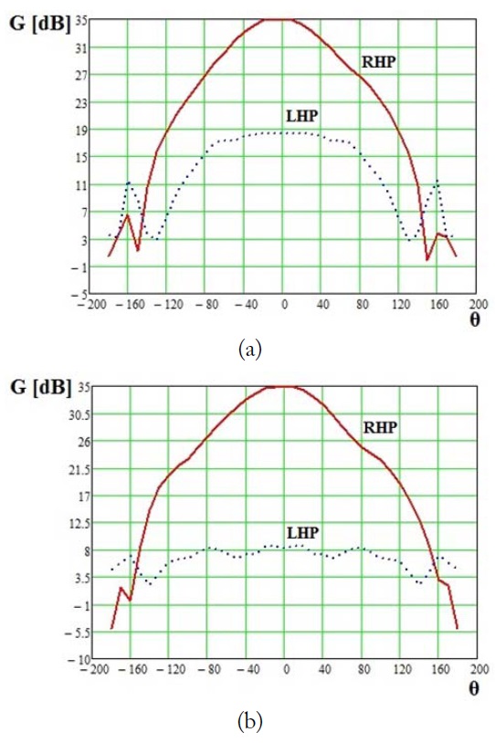
The antenna module radiation patterns, taken on the frequencies 1,590 MHz and 1,236 MHz are presented on Fig. 9. Diagrams show the wide radiation pattern in the top hemisphere and the maximum multipath mitigating level –40 dBi in
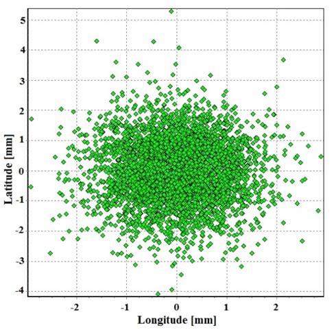
Using two antenna modules, installed stationary with the base between them 0.538 m, measurements of router point coordinates [21] within 24 hours were made. On Fig. 10 router point latitude and longitude deviations are presented. It is seen from the diagram that most reference point deviations are in the range ±2 mm, what means that the antenna phase center stability is better than 2 mm.
Thus, implementation of the EBG metamaterial in to vertical choke-ring construction allows obtaining antenna module better characteristics, which infect the accuracy of coordinate determination in special GNSS equipment—decrease the level of reflected signal and increase the antenna phase center stability.
It is shown that presented EBG frequency selective surface has metamaterial properties. Its flat structure allowed constructing a multiband multipath mitigating ground plane. A proposed special method of EBG metamaterial mounting, which main idea is to orient the EBG structure in the way to place its ground plane on the top hemisphere and the frequency selective surface (‘mushroom heads’) on the bottom hemisphere, allowed developing a construction of the multipath mitigating ground plane, which does not tight the antenna radiation pattern, what allows receiving signals from the satellites on low elevation angles, and does not spoil the phase center stability of the antenna module, what raises the antenna accuracy.
A dual bend GPS-GLONASS GNSS antenna module, which was designed and manufactured, using the presented EBG metamaterial structure and the presented method of multipath mitigating ground plane constructing, is presented. Its measured parameters demonstrated high performance characteristics of the EBG metamaterial and the multipath mitigating ground plane construction.