검색 전체 메뉴
PDF
맨 위로
OA 학술지
Experimental study on synthesis of Co/CeO2-doped carbon nanofibers and its performance in supercapacitors
  • 비영리 CC BY-NC
  • 비영리 CC BY-NC
ABSTRACT
Experimental study on synthesis of Co/CeO2-doped carbon nanofibers and its performance in supercapacitors
KEYWORD
supercapacitors , carbon nanofibers , electrospinning , cerium acetate , cobalt acetate
  • Because of avaricious global energy consumption, and serious environmental issues, the demand for clean energy technology has grown to a significant level, and the development of emerging effective energy devices and resources has become one of the most important topics in recent decades, and has attracted passionate research [1]. Among encouraging alternative sources of energy, supercapacitors are one of the promising electrochemical energy storage devices, with high power characteristics compared to batteries, high energy density compared to conventional capacitors, and long cycling times [2-6].

    Hence, supercapacitors have been practically used in various applications, and offer potential benefits in communications, consumer electronics, aviation, transportation and associated technologies [7-9]. It is well known that the performance of electrochemical double layer capacitors (EDLCs) typically depends on the high specific surface area and highly reversible redox reactions of the electrode materials [10]. Therefore, various carbonaceous materials, such as carbon nanotubes, activated carbons, carbon blacks, carbon aerogels and carbon fibers have been investigated as electrode materials for supercapacitors. Comparatively, carbon nanofibers (CNFs) have gained great importance in recent years due to their large axial ratio [11,12]. Presently, CNFs are extensively applied in many fields such as fuel cells, EDLCs, hydrogen energy and lithium-ion cells [13-17].

    On the other hand, various oxides of transition metals, such as manganese [18], cobalt [19], nickel [20], and tin [21] have been used as electrode materials for EDLCs, because of low cost and non-toxicity [22]. Furthermore, it has also been reported that Co based materials have good electrochemical activity [23] and the latest studies have shown that this metal does have good electrocatalytic properties if it can be supported by the proper co-catalyst [24].

    CeO2 has received considerable attention due to its remarkable properties and wide applications in various fields such as oxygen permeation membrane systems [25,26], low-temperature water-gas shift reaction [27,28], oxygen sensors [29,30], glass-polishing materials [31,32], and fuel cells [33-36].

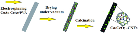
    In this paper, we demonstrate a methodology for the synthesis of Co/CeO2-doped CNFs, which are introduced as an electrode of electrochemical capacitors (EC). The proposed nanostructures were synthesized by the carbonization of an electrospun mat composed of cerium acetate, cobalt acetate, and poly(vinyl alcohol) (PVA) in an argon atmosphere at 700℃.

    Cobalt (II) acetate tetrahydrate (CoAc, 98%; Aldrich, St. Louis, MO, USA) and cerium (III) acetate hydrate (CeAc, 99.9%; Aldrich) were used as the precursors for Co and CeO2 while PVA with a molecular weight 65,000 g/mol (Aldrich) was used as the precursor for the carbon fiber.

    A mixture containing 75 wt% CoAc and 25 wt% CeAc was mixed with 15 g PVA aqueous solution (10 wt%). Finally the mixture was stirred at room temperature for 5 h to obtain a transparent mixture. The obtained sol-gel was electrospun at a high voltage of 21 kV using a direct current (DC) power supply at room temperature. The produced mats were dried at room temperature for 10 h and then under vacuum overnight at 70℃ and finally carbonized at 700℃ for 6 h in inert atmosphere (The diagram of the general synthesis of the nanocomposite is depicted in Scheme 1).

    0.002 g of the nanocatalyst, 20 μL of Nafion solution (5 wt%; Aldrich) and 400 μL of isopropanol were mixed together and sonicated for 45 min at room temperature. The dispersed nanocatalyst (15 μL) was spread by micro pipette onto the active surface of the glassy carbon electrode, which was then subjected to a drying process at 75℃ for 30 min.

    The electrochemical performance of the produced electrode was characterized by cyclic voltammetry using a three electrode electrochemical cell (VersaSTAT 4, USA) at room temperature in a 1 M KOH solution. The three electrode cell consisted of a working electrode, and a Pt wire and an Ag/AgCl electrode were used as the auxiliary and reference electrodes, respectively.

    Characterization experiments were carried out at room temperature. The phase of the CNF’s was identified by X-ray diffractometer (XRD, Rigaku, Tokyo, Japan) with Cu-Kα (λ = 1.54056 Å) radiation operating at 45 kV and 100 mA over a range of 2θ angle from 10° to 80°, scanning at a rate of 4°/min. The morphology, crystalline size, and crystal structure of the sample were determined by field emission scanning electron microscopy (FESEM; Hitachi S-7400, Hitachi, Tokyo, Japan) coupled with rapid energy dispersive analysis of X-ray (EDX), transmission electron microscopy (TEM) and high resolution transmission electron microscopy (HRTEM; JEM-2200FS, JEOL, Tokyo, Japan) operating at 200 kV equipped with EDX (JEOL).

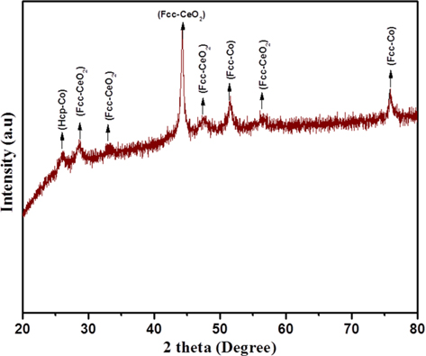
    Fig. 1 shows the XRD pattern of the Co/CeO2-CNFs, which were carbonized at 700℃ for 6 h. As shown in the figure, strong diffraction peaks were observed at 2θ values of 28.5°, 33°, 47.5°, and 56.3° (81-0792) corresponding to the (111), (200), (220), and (311) crystal planes, respectively, and indicating the formation of CeO2 with a face-centered-cubic (FCC) crystal structure.

    Regarding cobalt acetate, the XRD results show that the cobalt acetate has been decomposed to metallic Co, as the strong diffraction peaks at 2θ values of 44.35°, 51.65°, and 75.95° correspond to the (111), (200), and (220) crystal planes, respectively, with a FCC crystal structure (15–0806). Moreover, a hexagonal close-packed (HCP) Co could be also observed, as the standard peak representing that the formation of this phase can be seen at 26.21°, resembling the crystal plane of (201) (05–0727). Overall, the XRD outcomes confirm that FCC and HCP Co, and also FCC CeO2 structures, co-occur in the catalyst. It is worth mentioning that the absence of any peaks related to carbon can be attributed to the amorphous structure of the CNFs matrix.

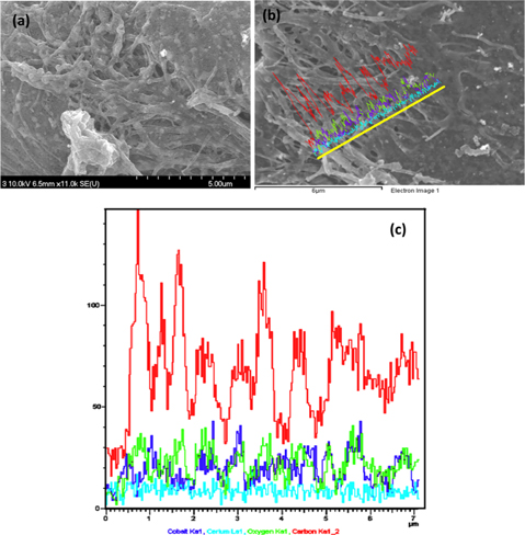
    FESEM images of the electrospun nanofibers containing CoAc and CeAc precursors after carbonization in an inert environment revealed good morphology. The nanofibers (NFs) are shown in Fig. 2a. As shown in the figures, nanofibers were formed with complete, clear and regular shapes with smooth surfaces, due to the small size of the bimetals. Furthermore all the bimetallic particles are on the surface of the nanofibers.

    To properly understand the composition and elementary analysis of the obtained Co/CeO2-CNFs, FESEM-EDX was carried out. The results are presented in Fig. 2b and c.

    Fig. 2c presents the EDX result corresponding to the line shown in Fig. 2b. As shown in Fig. 2c, Co, Ce, and O have the same elemental distribution along with the chosen line; moreover, the carbon elemental distribution confirms complete covering of the Co and CeO2 nanoparticles, as carbon is present at all points along the chosen line.

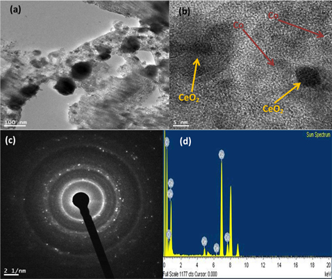
    Analysis of the internal structure of the as-prepared bimetallic CNFs was done using transmission electron microscope (TEM), and high resolution transmission electron microscope (HR-TEM). Fig. 3 shows the obtained results; Fig. 3a and b displays low and high resolutions, respectively.

    The bimetallic CNFs morphology is perfect in the image and the small black crystalline nanoparticles distributed on the nanofibers are surely Co and CeO2 nanoparticles. The Co and CeO2 nanoparticles are indicated in the HR-TEM image by dark yellow and dark red arrows in Fig. 3b.

    In order to confirm the existence of C, O, Ce, and Co in the nanofibers, TEM-EDX analysis was carried out. The results are presented in Fig. 3d. It was observed that the sample contains C, O, Ce, and Co; no other elemental impurities are detected.

    Fig. 3c shows the distinctive rings of the selective area electron diffraction pattern (SAED); the SAED image indicates the good crystallinity of the synthesized nanostructure.

    The prepared Co/CeO2 CNF’s were then used as electrode materials for a supercapacitor and its performance was analyzed using cyclic voltammetry.

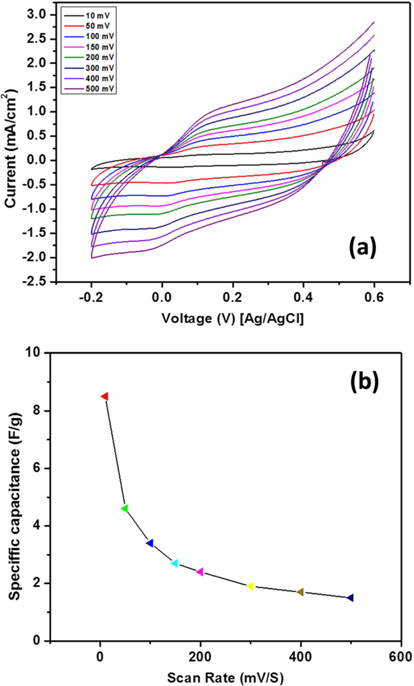
    The cyclic voltammetry (CV) curves of the nanocatalyst studied in a 1 M KOH solution at various scan rates are shown in Fig. 4a, and all the curves are perfectly rectangular in shape without any redox peaks, which shows that the sample has good capacitance behavior.

    It is well known the capacitance value depends upon scan rate so the effect of various scan rates on capacitive behavior was studied, and results are presented in Fig. 4b.

    The specific capacitance of the samples were calculated using the following eq [37,38]:
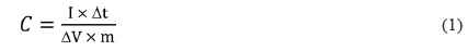
    image

    Here, C is the capacitance of the cell, m is the mass of the grafted material on the active surface of the electrode, I is the discharge current, Δt is the discharge time and ΔV is the voltage, respectively. A numerical integration model was established to calculate the specific capacitance as follows:

    where N is the number of points in the (CV cycle). As shown in Fig. 4, the corresponding specific capacitance of the introduced nanocatalyst is high at low scan rate (8.5 F/g) because the diffused ions from the solution can more easily access the electrode surface, which leads to more surface adsorption/desorption of ions [39], Moreover, the specific capacitance is relatively stable at the high scan rates.

    CNFs doped with Co/CeO2 nanoparticles with good morphology were prepared by the electrospinning of a sol-gel composed of cerium (III) acetate hydrate, cobalt (II) acetate tetrahydrate and poly(vinyl alcohol). The synthesized nanofibers can be utilized as operative inexpensive electrodes in electrochemical supercapacitors.

참고문헌
  • 1. Ghouri ZK, Barakat NAM, Obaid M, Lee JH, Kim HY 2015 Co/CeO2-decorated carbon nanofibers as effective non-precious electro-catalyst for fuel cells application in alkaline medium [Ceram Int] Vol.41 P.2271 google cross ref
  • 2. Ghouri ZK, Akhtar MS, Zahoor A, Barakat NAM, Han W, Park M, Pant B, Saud PS, Lee CH, Kim HY 2015 High-efficiency super capacitors based on hetero-structured α-MnO2 nanorods [J Alloys Compd] Vol.642 P.210 google cross ref
  • 3. Ghouri ZK, Barakat NAM, Park M, Kim BS, Kim HY 2015 Synthesis and characterization of Co/SrCO3 nanorods-decorated carbon nanofibers as novel electrocatalyst for methanol oxidation in alkaline medium [Ceram Int] Vol.41 P.6575 google cross ref
  • 4. Ghouri ZK, Barakat NAM, Kim HY 2015 Synthesis and electrochemical properties of MnO2 and co-decorated graphene as novel nanocomposite for electrochemical super capacitors application [Energy Environ Focus] Vol.4 P.34 google cross ref
  • 5. Ghouri ZK, Barakat NAM, Alam AM, Park M, Han TH, Kim HY 2015 Facile synthesis of Fe/CeO2-doped CNFs and their capacitance behavior [Int J Electrochem Sci] Vol.10 P.2064 google
  • 6. Zhang M, Jin X, Zhao Q 2014 Preparation of N-doped activated carbons for electric double-layer capacitors from waste fiberboard by K2CO3 activation [New Carbon Mater] Vol.29 P.89 google cross ref
  • 7. Burke A 2000 Ultracapacitors: why, how, and where is the technology [J Power Sources] Vol.91 P.37 google cross ref
  • 8. Yoda S, Ishihara K 1999 The advent of battery-based societies and the global environment in the 21st century [J Power Sources] Vol.81-82 P.162 google cross ref
  • 9. Becker HI 1957 US Patent google
  • 10. Hu CC, Chang KH, Lin MC, Wu YT 2006 Design and tailoring of the nanotubular arrayed architecture of hydrous RuO2 for next generation supercapacitors [Nano Lett] Vol.6 P.2690 google cross ref
  • 11. Barakat NAM, Kanjwal MA, Chronakis IS, Kim HY 2013 Influence of temperature on the photodegradation process using Ag-doped TiO2 nanostructures: negative impact with the nanofibers [J Mol Catal A Chem] Vol.336 P.333 google cross ref
  • 12. Barakat NAM, Abdelkareem MA, El-Newehy M, Kim HY 2013 Influence of the nanofibrous morphology on the catalytic activity of NiO nanostructures: an effective impact toward methanol electrooxidation [Nanoscale Res Lett] Vol.8 P.1 google cross ref
  • 13. Liu T, Gu S, Zhang Y, Ren J 2012 Fabrication and characterization of carbon nanofibers with a multiple tubular porous structure via electrospinning [J Polym Res] Vol.19 P.1 google cross ref
  • 14. Yousef A, Barakat NAM, Amna T, Abdelkareem MA, Unnithan AR, Al-Deyab SS, Kim HY 2012 Activated carbon/silver-doped polyurethane electrospun nanofibers: single mat for different pollutants treatment [Macromol Res] Vol.20 P.1243 google cross ref
  • 15. Barakat NAM, Akhtar MS, Yousef A, El-Newehy M, Kim HY 2012 Pd-Co-doped carbon nanofibers with photoactivity as effective counter electrodes for DSSCs [Chem Eng J] Vol.211-212 P.9 google cross ref
  • 16. Tao XY, Zhang XB, Zhang L, Cheng JP, Liu F, Luo JH, Luo ZQ, Geise HJ 2006 Synthesis of multi-branched porous carbon nanofibers and their application in electrochemical double-layer capacitors [Carbon] Vol.44 P.1425 google cross ref
  • 17. Tsuji M, Kubokawa M, Yano R, Miyamae N, Tsuji T, Jun MS, Hong S, Lim S, Yoon SH, Mochida I 2007 Fast preparation of PtRu catalysts supported on carbon nanofibers by the microwave-polyol method and their application to fuel cells [Langmuir] Vol.23 P.387 google cross ref
  • 18. Prasad KR, Miura N 2004 Potentiodynamically deposited nanostructured manganese dioxide as electrode material for electrochemical redox supercapacitors [J Power Sources] Vol.135 P.354 google cross ref
  • 19. Hosono E, Fujihara S, Honma I, Ichihara M, Zhou H 2006 Synthesis of the CoOOH fine nanoflake film with the high rate capacitance property [J Power Sources] Vol.158 P.779 google cross ref
  • 20. Wang Y, Xia Y 2006 Electrochemical capacitance characterization of NiO with ordered mesoporous structure synthesized by template SBA-15 [Electrochim Acta] Vol.51 P.3223 google cross ref
  • 21. Prasad KR, Miura N 2004 Electrochemically synthesized MnO2-based mixed oxides for high performance redox supercapacitors [Electrochem Commun] Vol.6 P.1004 google cross ref
  • 22. Toupin M, Brousse T, Belanger D 2004 Charge storage mechanism of MnO2 electrode used in aqueous electrochemical capacitor [Chem Mater] Vol.16 P.3184 google cross ref
  • 23. Nayak PK, Munichandraiah N 2008 Cobalt hydroxide as a capacitor material: tuning its potential window [J Electrochem Soc] Vol.155 P.A855-855 google cross ref
  • 24. Barakat NAM, Abdelkareem MA, Kim HY 2013 Ethanol electro-oxidation using cadmium-doped cobalt/carbon nanoparticles as novel non precious electrocatalyst [Appl Catal A Gen] Vol.455 P.193 google cross ref
  • 25. Stoukides M 2000 Solid-electrolyte membrane reactors: current experience and future outlook [Catal Rev] Vol.42 P.1 google cross ref
  • 26. Yin X, Hong L, Liu ZL 2006 Oxygen permeation through the LSCO-80/CeO2 asymmetric tubular membrane reactor [J Memb Sci] Vol.268 P.2 google cross ref
  • 27. Fu Q, Weber A, Flytzani-Stephanopoulos M 2001 Flytzani-Stephanopoulos M. Nanostructured Au-CeO2 catalysts for low-temperature water?gas shift [Catal Lett] Vol.77 P.87 google cross ref
  • 28. Fu Q, Saltsburg H, Flytzani-Stephanopoulos M 2003 Flytzani-Stephanopoulos M. Active nonmetallic Au and Pt species on ceria-based water-gas shift catalysts [Science] Vol.301 P.935 google cross ref
  • 29. Beie HJ, Gnorich A 1991 Oxygen gas sensors based on CeO2 thick and thin films [Sens Actuators B Chem] Vol.4 P.393 google cross ref
  • 30. Jasinski P, Suzuki T, Anderson HU 2003 Nanocrystalline undoped ceria oxygen sensor [Sens Actuators B Chem] Vol.95 P.73 google cross ref
  • 31. Feng X, Sayle DC, Wang ZL, Paras MS, Santora B, Sutorik AC, Sayle TXT, Yang Y, Ding Y, Wang X, Her YS 2006 Converting ceria polyhedral nanoparticles into single-crystal nanospheres [Science] Vol.312 P.1504 google cross ref
  • 32. Armini S, De Messemaeker J, Whelan CM, Moinpour M, Maex K 2008 Composite polymer core?ceria shell abrasive particles during oxide cmp: a defectivity study [J Electrochem Soc] Vol.155 P.H653 google cross ref
  • 33. Steele BCH 2000 Appraisal of Ce1?yGdyO2?y/2 electrolytes for IT-SOFC operation at 500℃ [Solid State Ionics] Vol.129 P.95 google cross ref
  • 34. Park S, Vohs JM, Gorte RJ 2000 Direct oxidation of hydrocarbons in a solid-oxide fuel cell [Nature] Vol.404 P.265 google cross ref
  • 35. Sun C, Hui R, Roller J 2010 Cathode materials for solid oxide fuel cells: a review [J Solid State Electrochem] Vol.14 P.1125 google cross ref
  • 36. Sun C, Stimming U 2007 Recent anode advances in solid oxide fuel cells [J Power Sources] Vol.171 P.247 google cross ref
  • 37. Xu B, Hou S, Zhang F, Cao G, Chu M, Yang Y 2014 Nitrogen-doped mesoporous carbon derived from biopolymer as electrode material for supercapacitors [J Electroanal Chem] Vol.712 P.146 google cross ref
  • 38. Mehmani A, Prodanovi? M 2014 The effect of microporosity on transport properties in porous media [Adv Water Resour] Vol.63 P.104 google cross ref
  • 39. Zou L, Li L, Song H, Morris G 2008 Using mesoporous carbon electrodes for brackish water desalination [Water Res] Vol.42 P.2340 google cross ref
OAK XML 통계
이미지 / 테이블
  • [ Scheme 1. ]  Schematic illustration of the synthesis process of Co/CeO2-doped carbon nanofiber (CNF)’s after calcination at 700℃ for 6 h in argon environment. PVA: poly(vinyl alcohol).
    Schematic illustration of the synthesis process of Co/CeO2-doped carbon nanofiber (CNF)’s after calcination at 700℃ for 6 h in argon environment. PVA: poly(vinyl alcohol).
  • [ Fig. 1. ]  X-ray diffractometer analysis of the obtained Co/CeO2 carbon nanofiber’s after carbonization at 700℃ for 6 h in argon environment. HCP: hexagonal close-packed, FCC: facecentered-cubic.
    X-ray diffractometer analysis of the obtained Co/CeO2 carbon nanofiber’s after carbonization at 700℃ for 6 h in argon environment. HCP: hexagonal close-packed, FCC: facecentered-cubic.
  • [ Fig. 2. ]  Field emission scanning electron microscopy image of Co/CeO2 carbon nanofiber’s (a) and EDX spectrum (b,c) of the produced nanofibers after carbonization at 700℃ for 6 h in argon environment.
    Field emission scanning electron microscopy image of Co/CeO2 carbon nanofiber’s (a) and EDX spectrum (b,c) of the produced nanofibers after carbonization at 700℃ for 6 h in argon environment.
  • [ Fig. 3. ]  Transmission electron microscopy image of Co/CeO2 carbon nanofiber’s (a) high resolution transmission electron microscopy image (b), the selective area electron diffraction pattern (c), and EDX spectrum (d) of produced nanofibers after carbonization at 700℃ for 6 h in argon environment.
    Transmission electron microscopy image of Co/CeO2 carbon nanofiber’s (a) high resolution transmission electron microscopy image (b), the selective area electron diffraction pattern (c), and EDX spectrum (d) of produced nanofibers after carbonization at 700℃ for 6 h in argon environment.
  • [ Fig. 4. ]  (a) Cyclic voltammogram for the Co/CeO2 carbon nanofiber’s composite in KOH solution at various scan rates. (b) Influence of scan rate on the specific capacitance.
    (a) Cyclic voltammogram for the Co/CeO2 carbon nanofiber’s composite in KOH solution at various scan rates. (b) Influence of scan rate on the specific capacitance.
  • [ ] 
(우)06579 서울시 서초구 반포대로 201(반포동)
Tel. 02-537-6389 | Fax. 02-590-0571 | 문의 : oak2014@korea.kr
Copyright(c) National Library of Korea. All rights reserved.