본 논문에서는 각 단말에 2개 이상의 안테나의 간섭 정렬을 이용한 X채널에서 직교 및 준직교 시공간 블록 부호를 통하여 더 높은 다이버시티와 전력 이득을 달성하고자 했다. 제안한 방법으로 다이버시티 차수는 직교 시공간 블록 부호에서 최대에 도달한 반면, 준직교 시공간 블록 부호에서는 유효 채널 행렬의 비 직교성에 의해 약간의 성능 저하가 나타났다. 수신기의 유효 채널 행렬에서의 유리한 구조에 의해 단순 제로 포싱 수신기는 최대 다이버시티 차수를 달성하는 반면, 간섭 제거 수신기는 성능이 저하되었다. 기존의 방법과 비교했을 때, 시뮬레이션 결과는 제안된 방법이 같은 스펙트럼 효율을 얻으면서, 3-4개의 안테나의 각 단의 직교 시공간 블록 부호의 경우 각각 목표 비트 에러율 10-4에서 14dB와 16.5bB의 이득을 얻는 것을 증명하였다. 또한 4개의 안테나의 각 단의 준직교 시공간 블록 부호의 경우 같은 목표 비트 에러율에서 10dB의 이득을 얻었다.
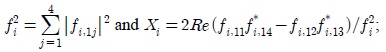
In wireless communications systems, interference plays a major role in defining the achievable performance and capacity [1,2]. In conventional receivers, in multi-user scenarios, the interference is either ignored, hence considered as an additional noise, or jointly decoded via employing successive interference cancellation (SIC) detectors [3-5]. In both cases, the dimension of the interference remains the same, leading to degraded performance and diversity gain in the first case, while powerful algorithms should be employed in the case of SIC so as to avoid degradation in the performance.
Interference alignment is a transmission technique used to reduce the dimensions of the interference while maintaining the useful signals discernible at the intended receivers. This is achievable by precoding the transmit signals such that the interference is aligned at unintended receivers [6]. As such, interference is removed at the intended receivers using simple mathematical operations leading to an interference-free system, where appropriate decoding algorithms can then be used to decode the useful signals. In [6], Jafar and Shamai proposed a linear alignment algorithm for the two-user X channel, that achieves the maximum data rate of (4/3 ×
In addition to the multiplexing gain, quantified by symbols/channel use, the diversity gain is an important measure of the system performance. When the channel is in deep fading, systems with unity diversity gain suffer from low signal-to-noise ratio (SNR) at the receiver side, leading to degradation in the bit-error rate (BER). Several diversity techniques have been proposed in the literature to explore further diversity gain [7-9]. In [10], a technique that combines interference alignment in X channel and Alamouti diversity scheme with two transmit antennas has been proposed to achieve the maximum multiplexing gain of (
In this paper, we propose several transmitter and receiver structures for the case of more than 2 transmit antennas aiming to increase the diversity and power gains. First, we examine the combination of orthogonal space-time block codes (OSTBC) for
The rest of the paper is as follows. In Section II we introduce the system model and review the LJJ scheme. In Sections III and IV, we introduce the OSTBCs and quasi-OSTBCs built on the 2-user X channel with interference alignment, respectively. In Section V we present the simulation results and in Section VI we draw the final conclusions.
Ⅱ. System model and related work
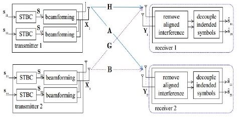
Consider a two-user X channel system as depicted in Figure 1, with each of the two transmitters equipped with
The elements of the noise matrices
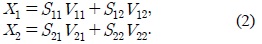
The beamforming matrices

where the real-valued scalars
In the LJJ scheme [10], each node is equipped with 2 antennas where each transmitter has

for
Ⅲ. Orthogonal STBC with Rc = 1/2 top of the x-channel With Interference Alignment
It is proven that Alamouti scheme is the only OSTBC with rate
3.1. Alignment design for orthogonal STBC with nT = nR = 3
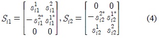
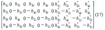
For the case of

and
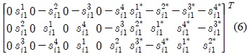
with (•)

where

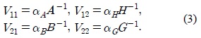
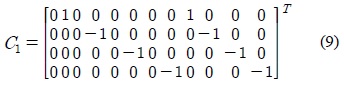
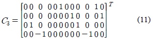
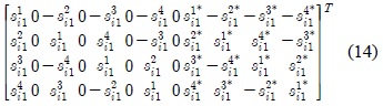
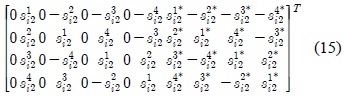
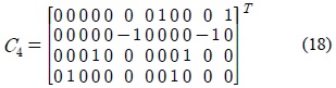
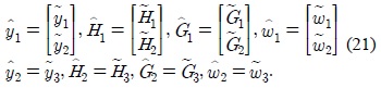
The aligned interference coefficient matrices are given by:


where , for
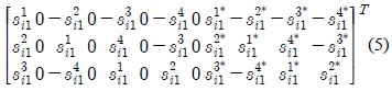
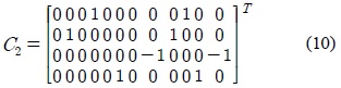
The aligned interference can be simply removed by constructing the set of vectors.
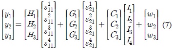
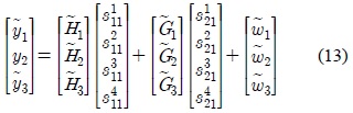
where the system becomes interference-free and is represented by the following equation.

with the 8×4 matrices being derived from
3.2. Alignment design for orthogonal STBC with nT = nR = 4
For the case of

and

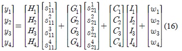
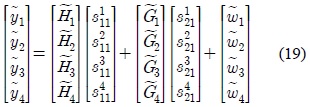
The 12×4 received matrices

where

In (16),

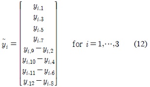
Now, let the vectors , for
with the 8×4 matrices being derived from
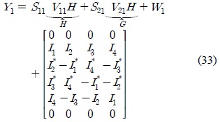
3.3. Decoupling Symbols from Different Transmitters
In the following, we introduce two decoupling algorithms; the first is an interference cancellation receiver (ICR) based on the work given in [10] and [11], whereas the second algorithm is the linear zero-forcing (ZF), where we shed light on the simplicity of the channel inversion due to the structure of the resulting interference-free system.
3.3.1. Interference cancellation receiver
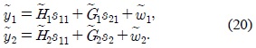
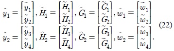
Let the interference-free system be represented by the following two equations.

where in the case of
In the case of

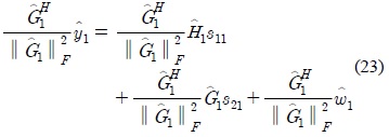
To decouple the vector

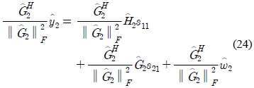
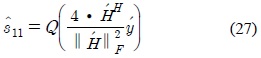
where ║

Let

then

Due the operation completeness of the matrices in 20, is also orthogonal. Then, the estimate of

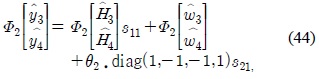
where
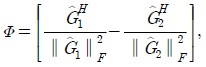
3.3.2. Linear receiver
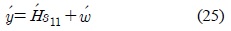
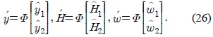
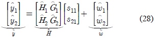
Let the system in (20) be reformulated as following.

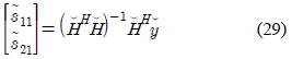
The estimate of the symbols from the transmitters are then obtained using the linear ZF detector as follows.

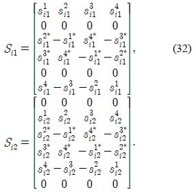
with the estimate of si1 is given by . Due to the structure of the matrices , for

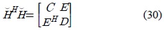
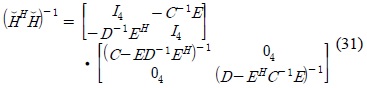
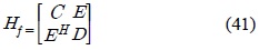
where the matrices C, D and E are real-valued with C and D being diagonal with diagonal elements equal to , respectively.
Based on the block matrix inverse lemma,

Note that the matrix (
Ⅳ. Full-rate Quasi-orthogonal STBC on top of the x-channel with interference alignment system
To achieve higher diversity gains employing a single receive antenna, the conventional Alamouti code [7] with two transmit antennas is extended to the 2
In the current design, (2) and (3) still hold with the difference that the matrices
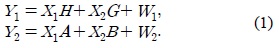
Based on (1), the 6×4 received signal matrices at receiver 1 and 2 are respectively written as

where , for
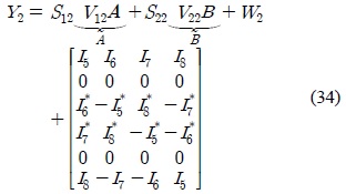
The aligned interference at receiver 1,
where the vectors for
Note that , for

where the noise is still white with a covariance matrix , where ⊗ denotes the Kronecker product and
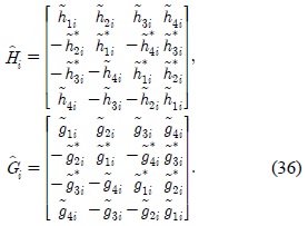
Before introducing the decoupling schemes, it is worthy to shed some light on the properties of the matrices given in (36), where these properties are essential in the design of the receiver. Let
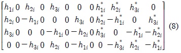
1) The matrix is real-valued, having the form

where

2) These matrices are complete in terms of matrix addition, matrix subtraction, and matrix multiplication. That is, the Gram matrix of
3) The inverse of given in Property I, has the following form
with
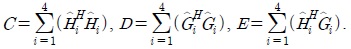
4) The sum of Gramians of the matrices defined in (36) is given by

with
Having that been said about the properties of the matrices given in (36), we introduce the properties of the Gramian matrix which will be used in the decoupling algorithms to be introduced in the sequel. The (8×8) Gramian matrix is given by:
where

Note that the 4×4 matrices C and D have the structure explained in Property 4, while the 4×4 matrix E has the structure given in (36). As such, it comes with no surprise that the inverse of
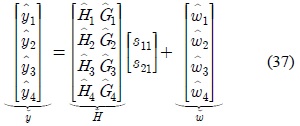
4.2. Decoupling symbols from different transmitters
In the literature, several detection techniques have been proposed [10], which can be used to decouple the symbols from different receivers in (37). However, the effective channel matrix, or matrices, in (37) has a special structure that motivates the proposal of modified receivers that take into account the particular structure of these matrices. In the following, we introduce the details of two receiver structures.
4.2.1. Interference cancellation receiver
The idea of the ICR is based on the work introduced in [10] and [11], with the particularity that the system discussed here is not orthogonal. That is, the Gram matrix of in (37) include both diagonal and skew-diagonal elements. As such, to decouple
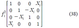
A) Cancellation of the diagonal elements: Starting with (38), we construct the following four vectors.

Where based on property 1

where diag() is a skew-diagonal matrix. Subtracting the second equation, i.e.,
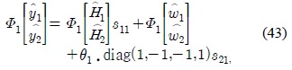

where
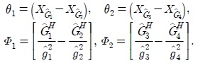
B) Cancellation of the off-diagonal elements: Let (43) and (44) be divided by

where . It is worth mentioning that based on Property II, the structure of is defined by Property I.
Finally, the ZF decoder can be used to recover the transmitted vector
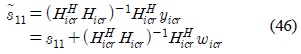
where the estimate . Note that can be computed using Property III to reduce the computational complexity.
4.2.2 Linear zero-forcing receiver
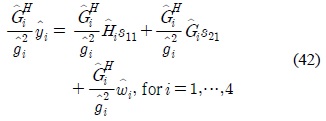
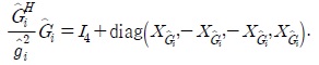
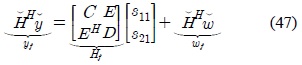
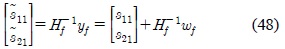
The system modeled in (37) is first filtered using resulting in

where , and the subscript f refers to filtered. As such, C and D have the structure given in Property 1, as well as satisfying Property 4, while E satisfies Property II. The transmitted vectors are recovered as follows
To avoid the inversion of the 8×8 matrix
1) C, D, (
2)
3)
Based on these remarks, it stems out that the computational complexity of the linear ZF detector is low due to the special structure of the effective channel matrices.
Ⅴ. Simulation Results and Discussion
In this section, we consider that each transmitter has full knowledge of
Figure 2 depicts the performance of OSTBC with code rate of 1/2 and
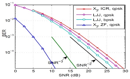
To hold a fair comparison between the proposed scheme and the LJJ scheme, we fix the spectral efficiency to 8/3 bits/s/Hz, implying that the modulation schemes used for and LJJ schemes are QPSK and BPSK, respectively. Starting with the ICR, due the increased dimensionality of the interference, this receiver fails to achieve the full diversity gain of
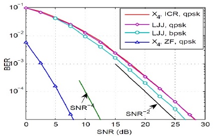
Figure 3 depicts the performance of OSTBC with code rate of 1/2 and
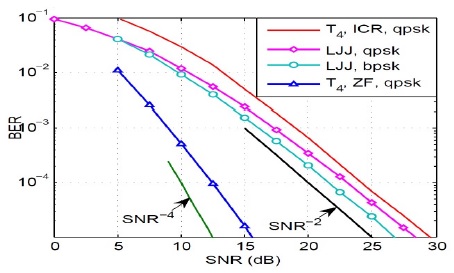
Finally, Figure 4 depicts the performance of the quasi-OSTBC with
In this paper, we introduced three schemes that achieve superior performances as compared to the conventional LJJ scheme in terms of BER and diversity order all at the same spectral efficiency. The first two proposed schemes, namely
As a future work, we plan to investigate the implementation of several quasi-OSTBCs with