Delay Tolerant Network (DTN) is an emerging area of networking that addresses challenges in disconnected, disrupted networks and commonly without end-to-end connection [1]. DTN provides communication infrastructure for environments with intermittent connectivity, long or variable delays, asymmetric data rates, high error rates and ambiguous mobility patterns [2]. Mobility of nodes is a valuable factor for routing in DTN [3, 4] and is an important feature that makes opportunistic contacts occurs. Mobility is innate among mobile device carriers (such as smartphone users, vehicles with access points) which can be utilized in DTN to assist message transmission.
With nodes’ mobility and dynamic movement pattern, several context information can be extracted. Context information has been very useful for location-aware systems that have been implemented in various discipline like disaster response, recommender systems, mobile social networks and environmental monitoring and forecasting. According to Schilit et al. [5] context information may refer to an entity’s (person, place, or object) location, identities, nearby people and objects, and changes to those entities. It is also viewed as any information that can be used to characterize the situation of an entity that is considered relevant to the interaction between a user and an application, including the application themselves. The availability of this information and its dynamic nature are the promising aspects why several applications have benefited from using it.
The main contribution of this paper is the context-information based routing algorithm that evaluates each message’s probability of delivery if given to an intermediate node (IN) in contact with the source node (SN). The proposed routing approach involves estimating the nodes position and determining if the IN would encounter the message’s destination node (DN). Most of the concepts of selecting the best forwarder for message delivery are adopted from the equations of a straight line involving the slope and y-intercept [6]. The concept of considering the differentiation of messages is commonly neglected in designing routing protocols where another contribution of this paper is the energy-based message prioritization rule that makes sure important messages are given the utmost attention for delivery.
The remainder of this paper is structured as follows: section 2 discusses the motivation and objectives. Section 3 explains in detail the proposed approach and section 4 presents the simulation settings and scenarios. The results of the simulation and discussion are depicted in section 5 and lastly, section 6 concludes this paper.
From the observation made on the works in [7, 8], over replication is both an advantage and a disadvantage in routing protocols for DTN. This routing strategy helps several protocols like Spray and Wait [9] at the cost of giving burden to the storage and energy capacity of the node. With this problem, the proposed routing scheme is made to control over-replication in a sense that it only chooses the best forwarder for messages that has higher possibility of contact with the destination. Thus, this results to less relayed messages without compromising success of delivery.
Localization schemes in wireless sensor network (WSN) using RSSI (received signal strength indicator) through anchors have also motivated this study to utilized context-information and geometric relationship of nodes for routing in DTN [10]. Localization scheme brings forth an oracle assessment of where the nodes are and can be exploited in extent of message transmission, especially in helping to choose the best forwarder [11]. When the geographic placement of the message destination is known, certain criteria like (link quality, distance, energy consumption) can be used as metric to evaluate if nodes are capable of delivering the messages.
Energy-efficiency is one desirable characteristic routing protocols should possess and most of the time protocol designs fail to embody it. Moreover, most routing protocols in literature treat each message equally resulting to inadequacy to consider prioritization of messages, especially in low energy level situations [12]. However, some applications like military networks and disaster response systems need to consider differentiation of messages priority levels and recognize important messages that needs faster delivery.
One of the main objective of using context information is to ensure balance in the performance of the routing scheme particularly in delivery ratio, overhead ratio, latency or delay and message prioritization. The use of context information for routing and choosing the best node forwarder aims to avoid unnecessary message copies that causes bottleneck and message congestion within the nodes.
In this section, we present in detail the context informationbased routing with energy-based message prioritization rule for Delay Tolerant Networks called CMP. CMP belongs to the context-based routing category that falls under the deterministic routing protocols for DTN. In particular, the routing scheme is partially deterministic as it estimates the position of the destination at the current contact period and at a particular point in time. One of the peculiar characteristic of CMP is its strict selection of the node forwarder for message delivery by evaluating if the intermediate node (IN) has higher possibility of meeting the destination node (DN) than the source node (SN). The SN and IN’s trajectory and position is calculated and is compared that of the DN. The following subsections further elaborate this process.
The routing scheme implemented essential components, which includes the Contacts, Connection Message Tables, and energy-based message prioritization rule, and are described as follows.
3.1.1 Contacts Table (CT)
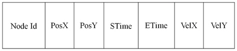
During encounters, nodes exchange several valuable information for message delivery. This information includes the summary vectors (list of messages currently on nodes storage) [13] and routing table. For the proposed approach, we implemented a Contacts Table (CT) to record the context information of nodes during contact. The CT format is illustrated in Figure 1.
3.1.2 Message Connection Table (MCT)
This table records the updated context information of the message destinations (DNs) currently in SN’s storage. It also records all IN who has been given shared responsibility of delivering the message to the destination, which includes the destination information (ID, context information), elapsed time (ET), and node Id of the IN selected as forwarder. For all the SN’s messages evaluated to be transmitted to an IN, this table also stores a temporary list of those messages. These messages will then be retrieved to undergone checking by the energy based-message prioritization rule.
3.1.3 Energy-based Message Prioritization
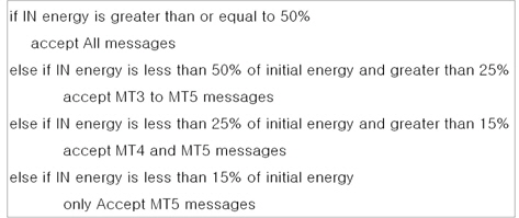
The energy-based message prioritization rule decides what type of messages can be transmitted and has higher chance of delivery to the destination. The deciding factor of the prioritization rule is the remaining energy of the IN in contact. This message prioritization rule is adopted from the work in [14], which prioritizes important packets in a body sensor network (BSN) for patient monitoring. The delivery capability of the IN is particularly dependent on its remaining energy and as node energy decreases; its communication capability also decreases. Therefore, when node reaches low energy level it must only consume its energy to the messages that are of great importance to the application.
This message prioritization rule is called out after every message has been evaluated to be transmitted to the IN. The message prioritization pseudocode is shown in Figure 2.
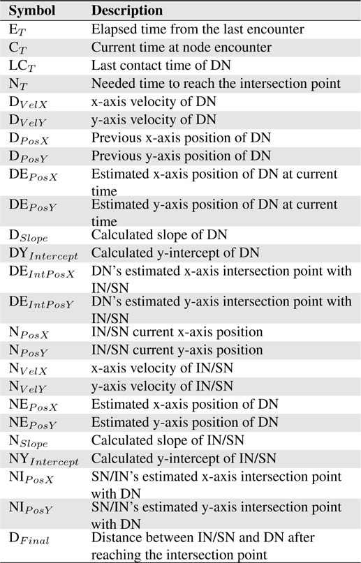
The proposed routing scheme is divided into three (3) routing phases namely CT exchange and update, connection message table update, and forwarder node selection. The notations presented in Table 1 are used in routing algorithm of proposed scheme. The routing phases are describe in detail in the following subsections.
[Table 1.] Notations and description for the routing algorithm

Notations and description for the routing algorithm
3.2.1 Contacts Table Exchange and Update
The routing phase starts with the context information exchange after the nodes establish the connection. The Contacts Table (CT) described in previous section holds information about each node’s contact of other nodes in the network. CMP makes use of the CT to obtain information for every message destination that SN currently have in its storage.
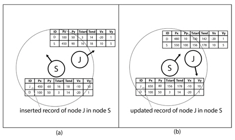
When both nodes encounter each other for the first time, SN and IN puts a new record of the contact in the CT and an update of the contact record happens when there is already a previous record of the nodes meeting each other.
Figure 3 describes the CT adding and updating scenario when nodes S and J encounter each other for several times at different periods. This means that the CT of nodes are updated through encounters and technically contains the recent context information of nodes in the network.
3.2.2 Connection Message Table Update
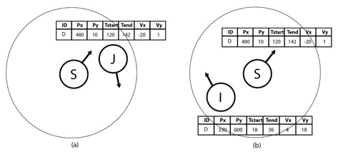
After the context information exchanged, the routing scheme performs a connection message update for every message destination in the SN’s storage. This phase retrieves the recent context information of the message destinations from the IN’s Contacts Table. Figure 4 shows the encounter scenario of nodes S, I and J and the updating of context information of node D.

3.2.3 Forwarder Node Selection
The forwarder node selection is the very core aspect of CMP. This is where a node is determine if it will be a reliable forwarder to deliver the message to the destination. From the updated connection message table, the routing scheme performs a comparison of the distance of the SN and IN to the DN based on their moving direction, velocity and current position. The concepts applied here are adopted from the equations of a straight line [6]. In general, a straight line is the shortest path from one point to another, thus, it is reasonable to assume that nodes under general conditions will follow a straight path trajectory. This routing phase is subdivided into series of steps:
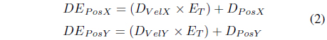
1) DN Position Estimation
The next step after getting the recent context information of every message destination in SN is the calculation of the estimated position of DN at current contact time. This method is taken from the concept of determining the velocity of a moving object, v = Δd/Δt, where v is the velocity (speed with direction) of the object, d is the distance and t is the time. Eq. (2) shows how to calculate DN’s estimated position.

2) Determine the Trajectory of the DN
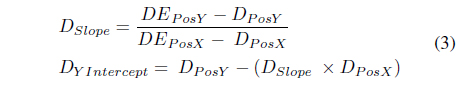
To determine the trajectory of the destination, we should define the equation of the line representing its trajectory using the slope-intercept form (y=mx+b), where m is the slope and b is the y-intercept. To solve for the slope, we use the the change of the value of the y coordinates over the change of value in x coordinates (m = Δy/Δx), and since x and y position of the node is available, the y-intercept should be calculated as b=y−mx. The estimated position of the DN calculated from the previous step is the first coordinate and the second coordinate is the DN’s last known position that is further used to determine the slope and y-intercept. Eq. (3) shows the formula to calculate the slope and y-intercept of the DN.

3) Determine the Trajectory of the IN/SN
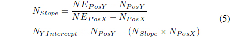
In order to determine if the IN will move towards the DN’s position, its trajectory is also determine using the same set of equations in determining the DN’s estimated position. Eqs. (4) and (5) show the calculation for the trajectory of the IN/SN. In this case, unlike the DN’s position that has been determined using the elapsed time (ET), we utilized a time interval of four to estimate its position at a particular time. The time interval has little effect on the trajectory of nodes since the primary factor that dictates it is its velocity.

4) Calculate for the Intersection point of the IN/SN and the DN
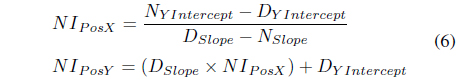
When the trajectories of the nodes are determine, the routing scheme identifies the possible intersection point of IN/SN with the DN. To calculate for the intersection point, the calculated y-intercepts and the slopes in the previous steps are used as shown in Eq. (6). The primary goal of this step is to determine at what specific location point the nodes will intersect each other within a certain radius of transmission range.
5) Compute for the needed time for IN/SN to reach the Intersection Point and Estimate the DN’s position by the time the IN to reach the Intersection point
This step ensures that the selected IN will have the shortest time to reach the estimated intersection point. This step will also verify if the IN will deliver the message at the best possible time. Since the velocity (v= Δd/Δt) of the IN/SN is available, the time interval t or the needed time for an object to reach a specific point can be determine. Using the calculated intersection point of the nodes (IN/SN and DN) in the previous step the calculated needed time for the node to reach it is shown in Eq. (7) below.

The calculated position of the destination on the first routing phase denotes its current location at the time of contact of the SN and IN. In contrast, this particular step determines the estimated position of the destination when the IN reaches the calculated intersection point Eq. (8) shows how to solve this. Furthermore, this step checks if both the DN and IN will be inside each other’s transmission range to be able to transmit messages.

6) Calculate the distance between IN and DN at the time IN reach the intersection point
Lastly, and the most important step that will determine if a message will be given to the IN from the SN is to determine the distance between the DN and IN/SN using the calculated intersection points from step 3 and 6. In Eq. (9), using the Pythagorean Theorem, the distance between the IN/SN and the DN when it reached the intersection point is determine.
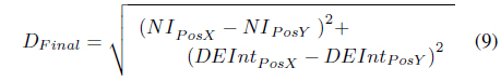
The final distance (
The final distance (DFinal), node ID of IN and the elapsed time (ET) are recorded in the message connections table as the best connection for each message. In DTN, since nodes store messages with different destination in their buffer for a certain period, our proposed scheme exhibit the restriction of sending messages to the IN when it has low possibility of meeting the destination compared with the SN. The routing scheme also suggests that only few messages are given to an IN. In particular, the messages that are only evaluated are those whose destination might have the possibility of meeting the IN.
When all messages have been evaluated and added on the SN’s queue, the energy based prioritization rule will check all these messages and allow only the message types according to message prioritization rules.
Opportunistic Network Environment (ONE) is used for the simulation. ONE is a Java-based simulation environment that combines movement modelling, routing simulation, visualization and reporting in one program [15]. We utilized the Epidemic [16] and Prophet [17] routing schemes available in ONE for comparison.
4.2 Simulation Settings and Scenarios
The following simulation settings and scenarios are used to evaluate the performance of CMP, Epidemic and Prophet.
4.2.1 Mobile Urban Setting
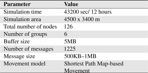
This simulation scenario involves mobile carriers in an urban area. We used the Helsinki area to emulate a daily routine of moving people, cars and trams. Vehicles (cars and trams) have map route movement that can be set using mapRoute-File in ONE. The energy settings are listed in Table 2 and the simulation settings is depicted in Table 3, respectively.
[Table 2.] Energy settings for the simulation
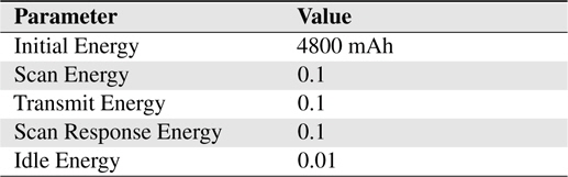
Energy settings for the simulation
[Table 3.] Environmetn settings for simulation

Environmetn settings for simulation
4.2.2 Random Initial Energy
This simulation scenario involves nodes with random initial energy for the start of the simulation. The initial energy of the nodes are set to be in the range of 3600mAh (75% from the initial energy) to a full 4800mAh battery level. This scenario meant to replicate a real world scenario where mobile devices are not of the same energy levels when using a particular mobile service supported by DTN. The number of messages created on this scenario is set to 250.
The following subsection presents the metrics used in the performance evaluation of routing protocols.
Delivery Ratio. Delivery ratio is defined as the ratio of number of messages received by destination nodes to the number of messages created.
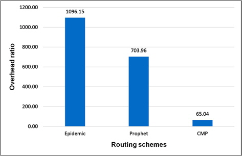
Overhead Ratio. Overhead ratio is computed as the difference of relayed and delivered messages divided by the number of delivered messages.
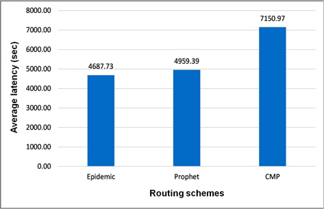
Average Latency. Average latency is a fundamental performance metric representing the average delivery time for a message from source node to destination.
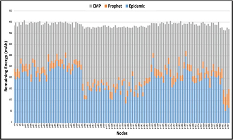
Residual Energy. It represents the average remaining energy values of the nodes when the simulation ends.
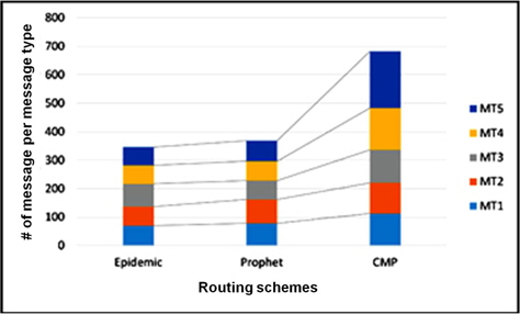
Delivered Messages per Message Types. This describes the number of messages delivered for each message types. This metric will also verify if messages with higher degree of importance has more successful deliveries than those that are not.
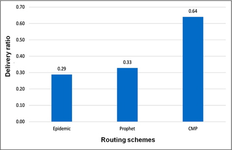
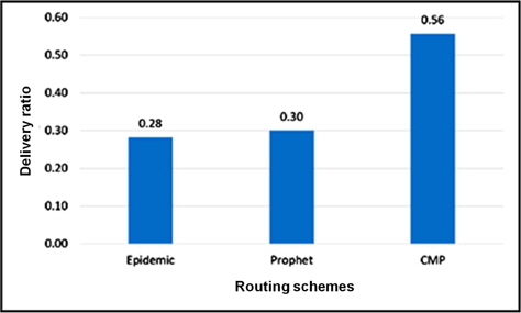
The mobile urban setting is comprised of heterogeneous DTN nodes (pedestrians, cars, trams) with different speed and buffer spaces have yielded results in favor of CMP. Figure 5 to 9 show the results for the performance of the first simulation scenario. The success of delivery for CMP is about 20% higher compared to the Epidemic and Prophet as shown in Figure 5.
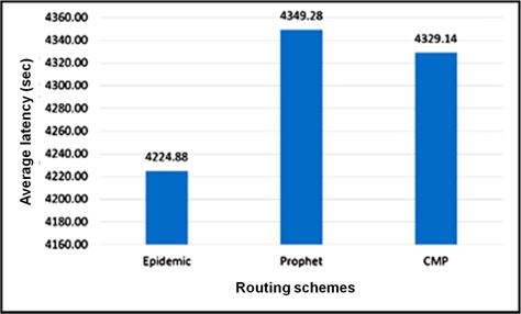
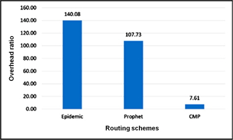
We observed that the speed variation and the map-based movement have effect on these results. A high difference in terms of overhead ratio is seen in Figure 6. The number of relayed messages of CMP is minimal as the routing algorithm finely selects the best forwarder for each message. However, a small difference is seen for the average delay of CMP compare to Prophet in Figure 7. This figure also shows that with the different speed of nodes a faster delivery of messages can be achieved.
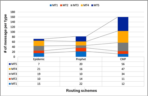
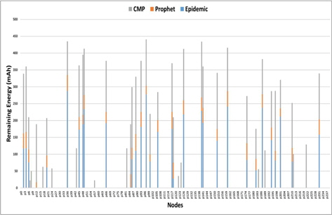
For this scenario, all routing protocols have a good mix of message types delivered to the destination but CMP clearly prioritizes message types MT4 and MT5 as it energy becomes low. We observed a fairness of delivery for all message types during high energy level even if the messages are queued based on their message type and size as shown in Figure 8. Figure 9 shows the average remaining energy of nodes at the end of the simulation. The remaining energy of nodes using CMP is higher compared to the other two (2) routing schemes as shown in Figure 9.
This particular scenario emulates what might be the situation of a publish-subscribe mobile application platform at the start of the day. Users have different battery levels, which uses the application service. From the results of the simulation shown in Figures 10 to 14, CMP still outperforms Epidemic and Prophet in terms of message delivery and energy-efficiency. With all other simulation scenarios, the delivery ratio in Figure 10 reached 60% as the number of created messages is set to 250.
In Figure 12, we observed that the average latency was high compare to the previous scenarios, which is a direct trade-off of the achieved low overhead ratio in Figure 11 and result of the unacceptance of other messages for delivery because of low energy. The number of nodes chosen as the forwarder of messages becomes lesser, resulting to fewer message transmission or relay.
The result in shown in Figure 13 clearly shows the advantage of CMP in transmitting MT3 to MT5 types of messages. Due to the random starting energy level of nodes, a higher number of important messages are already prioritized as soon as node’s energy level reaches the 50% and 25%. This also results to more number of dead nodes at the end of the simulation as depicted in Figure 14.
In this paper, we presented an energy-efficient context-information based-routing scheme with energy-based message prioritization for Delay Tolerant Networks. The scheme is comprised of several components to perform effective routing of messages to reach destination. It involves making use of other nodes as anchor nodes that holds contact record of the message destinations. Estimation of the destination node position and calculation of the possibility of the intermediate node (IN) to make contact is mostly done using the formulas from equations of a line. An energy-based message transmission rule was also implemented to efficiently use node’s energy in accepting messages (prioritizing important ones) during low energy level.
The performance of the proposed approach (CMP) was compared with two (2) existing routing protocols Epidemic and Prophet by extending the ONE simulator. We performed two (2) different simulation scenarios in order to investigate in detail the performance of the proposed approach. The first scenario includes heterogeneous setting of mobile devices in an urban environment; the second scenario involves random starting energy levels that proved the energy efficiency and the effectiveness of the message prioritization rule. Most of the results yield better performance in all aspects (especially delivery ratio) for the proposed approach. However, the proposed scheme made certain trade-offs like slightly higher latency and buffer time occupancy in exchange for a low overhead and high number of important messages delivered. These trade-offs seems inevitable but are observed well-balanced compare to the performance of other routing schemes.
To further validate the effectiveness of the proposed approach, a more intensive simulation should be done with consideration of the contact time and contact frequency and changing speed of the nodes. A comparison with an existing context-information based routing scheme similar to the proposed approach would also give insights on its insufficiencies and limitations. Lastly, other context information should be investigated to improve the routing performance of the proposed approach.