검색 전체 메뉴
PDF
맨 위로
OA 학술지
Analysis of Optimal Sounding Signal Design in OFDM Systems
  • 비영리 CC BY-NC
  • 비영리 CC BY-NC
ABSTRACT
Analysis of Optimal Sounding Signal Design in OFDM Systems
KEYWORD
MMSE , OFDM , Pilot signal , Sounding signal
  • I. INTRODUCTION

    Orthogonal frequency division multiplexing (OFDM) is a widely used technique for high-speed data transmission in a frequency-selective fading environment. To achieve a high data rate as well as good performance, coherent detection is commonly used in most of the existing OFDM systems [1]. Coherent detection relies on the knowledge of the channel state information (CSI). One simple approach to obtain CSI is to send sounding symbols from the transmitter.

    Many studies have been conducted on sounding signal design and channel estimation in pilot symbol-assisted OFDM (PSA-OFDM) systems. The locations of these sounding symbols along with the data stream, i.e., the sounding signal pattern, were examined in [2] and [3]. Other techniques for optimal sounding signal design that use the least-squares (LS) or the minimum mean square error (MMSE) method for OFDM channel estimation can be found in [4] and [5]. In particular, in [6], necessary and sufficient conditions were derived for optimal training sequences for the LS method, and a lower bound on the variance of the channel estimation was derived. In [7], an optimal design was considered by minimizing the channel mean square error (MSE). In [8], the symbol error rate was employed as a criterion for the optimization of the sounding signal design. In [9], pilot signal optimization for channel estimation was considered to be a minimization problem and was solved with iterative algorithms. Several approaches have been proposed for the sounding signal of MIMO systems, but not all these approaches have been mathematically verified with prior statistical information about the channel. In [10], an MSE performance close to that obtained by optimal orthogonal sequences was achieved at a considerably low implementation complexity. There are several methods for MIMO-OFDM systems with the general case of spatial correlations reported in [11] and [12].

    In this paper, we derive the optimal sounding signal characteristics for MMSE channel estimation assuming that second-order channel statistics are known in the SISOOFDM case. Furthermore, we show that a maximal-length shift register sequence (M-sequence) is appropriate for the optimal training sequence.

    The rest of this paper is organized as follows: Section II presents the mathematical model of channel estimation for SISO-OFDM systems and implements the optimal training sequence design on the basis of the MMSE criterion. Section III verifies an optimal sounding signal design to optimize the training sequences for a general MMSE criterion. Simulation results are provided in Section IV, and conclusions are drawn in Section V.

    II. SIGNAL MODEL

    We have formulated the following SISO-OFDM MMSE system model for channel sounding:
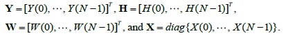
    image

    where

    image

    Note that Y(k) denotes the fast Fourier transform (FFT) of the received sounding signal, H(k) represents the channel frequency response, W(k) indicates the noise, and X(k) refers to the amplitude of the sounding signal in the k-th subcarrier out of N subcarriers.

    Our model of the second-order statistics of the channel can be described as in [13]:

    image

    where E(•) reprents the expectation of a random variable, h(p, q) denotes the channel impulse response from the p-th time slot to the q-th channel tap, (•)* denotes a complex conjugate transpose, C indicates a constant value of the amplitude of the channel element, J0 (•) refers to the Bessel functions of the first kind, fd indicates the Doppler frequency, Ts represents the symbol duration, α denotes the decay factor, L refers to the multipath delay spread in samples, and δ (•) denotes the Dirac delta function.

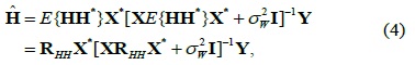
    The standard MMSE estimate of H, based on the observation of Y, is written as follows:

    image

    Using (1), we can express as follows:

    image

    where denotes the variance of the noise, I represents the identity matrix, and RHH = E {HH*} indicates the covariance matrix of the channel matrix, H.

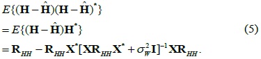
    The covariance matrix can be expressed as follows:

    image

    By applying the well-known matrix identity, (A+BCD)-1 = A-1 - A-1B (C-1+DA-1B)-1DA-1, we can rewrite (5) as follows:

    image

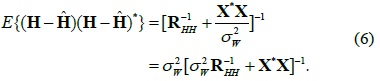
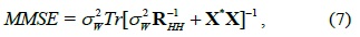
    Therefore, the MMSE of H can be derived as follows:

    image

    where Tr denotes the trace of an square matrix.

    III. OPTIMAL SOUNDING SIGNAL DESIGN IN SISO-OFDM SYSTEMS

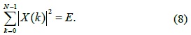
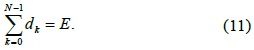
    We consider finding a sounding signal that minimizes the MMSE, subject to the following energy constraint:

    image

    To solve this problem, we need to find the diagonal matrix X that minimizes (7) subject to the above constraint. Recall that the diagonal elements of X are the sounding signal amplitudes in all subcarriers as defined above.

    image

    As in (9), the MMSE depends not on the phase angles of the sounding signal in all subcarriers but on their magnitudes. Let us, therefore, assume that dk = |X(k)|2 and D = X*X = diag {d0,d1,...,dN-1}. Then, (7) can be expressed as follows:

    image

    Thus, we have the ultimate goal of obtaining the nonnegative diagonal elements dk by minimizing (10) subject to the following constraint:

    image

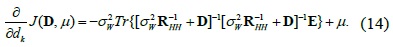
    We can mathematize the objective function in (10) by using the Lagrange multiplier method with the constraint defined in (11). By letting
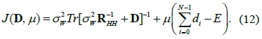
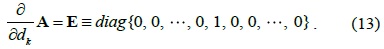
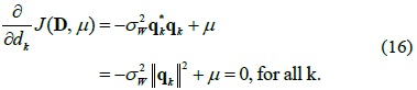
 μ be the Lagrange multiplier, we can formularize the Lagrange equation J (D, μ) as follows:

    image

    Thus, we set ∂J(D,μ)/∂dk = 0. Using the property that for any matrix A depending on a parameter x, ∂A-1/∂x = -A-1 (∂A/∂x)A-1, which involves AA-1 = I, we can solve the partial differentiate ∂J(D,μ)/∂dk by substituting and dk for A and x, respectively, as follows:

    image

    Note that 1 in (13) is the
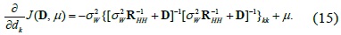
 k-th diagonal element. Thus, by applying the property Tr(AB) = Tr(BA) to (12), we acquire the following:

    image

    By considering Tr {ME} = Mkk , which is the k-th diagonal element of any diagonal matrix M, we can rewrite (14) as follows:

    image

    By defining qk as the k-th column of in (15) and using the fact that is Hermitian, we conclude that

    image

    We can show that the optimum D results in all qk having an equal norm. Further, we verify that the solution that satisfies these conditions is that all dk should be equal; i.e., all sounding signal amplitudes in all subcarriers should have an equal magnitude, or equivalently, D should be a multiple of the identity matrix. First, the channel matrix can be expressed as follows:

    image

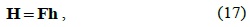
    where h denotes the impulse response matrix of the channel and F represents the FFT matrix. Therefore, it can be shown readily that RHH represents a circulant matrix assuming that the impulse response taps are uncorrelated. As is well known, RHH can be expressed as follows:

    image

    By assuming that D is a multiple of the identity matrix, D = βI, we can rewrite (18) as follows:

    image

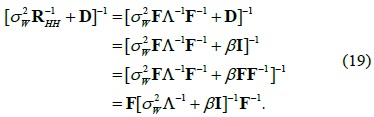
    Since is a diagonal matrix, the matrix of (19) is a circulant matrix. Because its columns have an equal norm and the matrix D satisfies the equations of optimality, the optimum sounding signal has sounding signal amplitudes with equal magnitudes in all subcarriers across the frequency band.

    IV. SIMULATION RESULTS

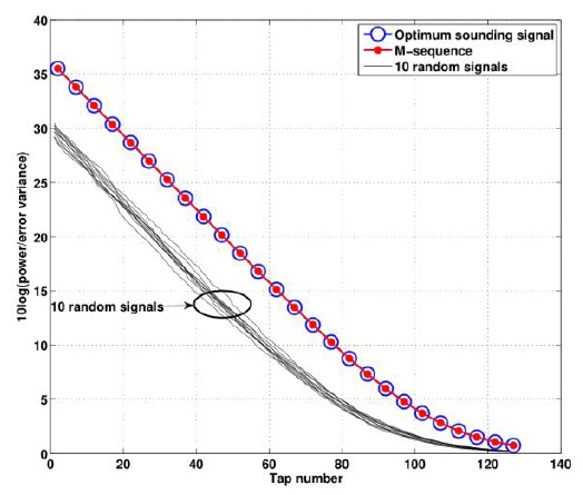
    In Fig. 1, the curve marked with blue circles corresponds to the performance of the optimum sounding signal, and the other curves are for 10 different sounding signals whose amplitudes in all subcarriers are complex Gaussian random variables, independent of the frequency. The simulation parameters are as follows: guard interval of length 128, Tg = N = 128, average signal-to-noise power ratio (SNR) = 20 dB, decay parameter α = 10, the number of sounding symbols Ms = 1, and the Doppler bandwidth is fdTs = 0. The FFT of the autocorrelation function of the sounding signal is identical to the squared magnitude of the transform of the signal itself. Since the optimum autocorrelation function is an impulse in the time domain, the optimum sounding signal outperforms the random sounding signals.

    In addition, Fig. 1 presents a comparison of the optimum sounding signal and an M-sequence. Note that the performance of the M-sequence is indistinguishable from that of the optimum sounding signal, since the autocorrelation of the M-sequence corresponds approximately to an impulse in the time domain.

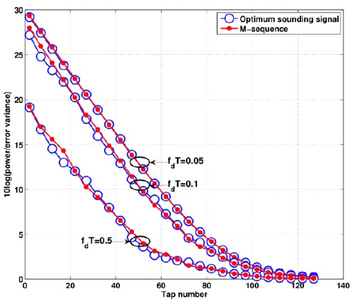
    Fig. 2 presents a comparison of the BER performance in the cases of the optimum sounding signal and the M-sequence for several different Doppler effects. The simulation parameters are identical to those considered in Fig. 1, except for the Doppler effect . fdTs. We can show that the M-sequence has a comparable performance to the optimum sounding signal in all cases, fdTs = 0.05, 0.1, and 0.5.

    V. CONCLUSIONS

    In this paper, we derived the optimal sounding signal characteristics for MMSE channel estimation assuming that the second-order channel statistics are known in the SISO-OFDM case. We found that the optimum sounding signal has an equal magnitude in all subcarriers across the frequency band. Through simulations, we found that the optimal sounding signal outperforms random sounding signals. In addition, we showed that the M-sequence is appropriate as an optimal training sequence.

참고문헌
  • 1. Bahai A. R., Saltzberg B. R., Ergen M. 1999 Multi-Carrier Digital Communications: Theory and Application of OFDM. google
  • 2. Song B., Gui L., Zhang W. 2006 “Comb type pilot aided channel estimation in OFDM systems with transmit diversity,” [IEEE Transactions on Broadcasting] Vol.52 P.50-57 google cross ref
  • 3. Zhang W., Xia X. G., Ching P. C. 2006 “Optimal training and pilot pattern design for OFDM systems in Rayleigh fading,” [IEEE Transactions on Broadcasting] Vol.52 P.505-514 google cross ref
  • 4. Morelli M., Mengali U. 2001 “A comparison of pilot-aided channel estimation methods for OFDM systems,” [IEEE Transactions on Signal Processing] Vol.49 P.3065-3073 google cross ref
  • 5. Minn H., Al-Dhahir N. 2006 “Optimal training signals for MIMO OFDM channel estimation,” [IEEE Transactions on Wireless Communications] Vol.5 P.1158-1168 google cross ref
  • 6. Manton J. H. 2001 “Optimal training sequences and pilot tones for OFDM systems,” [IEEE Communications Letters] Vol.5 P.151-153 google cross ref
  • 7. Barhumi I., Leus G., Moonen M. 2003 “Optimal training design for MIMO OFDM systems in mobile wireless channels,” [IEEE Transactions on Signal Processing] Vol.51 P.1615-1624 google cross ref
  • 8. Cai X., Giannakis G. B. 2004 “Error probability minimizing pilots for OFDM with M-PSK modulation over Rayleigh-fading channels,” [IEEE Transactions on Vehicular Technology] Vol.53 P.146-155 google cross ref
  • 9. Bogale T. E., Le L. B. 2014 “Pilot optimization and channel estimation for multiuser massive MIMO systems,” [in Proceedings of the 48th Annual Conference on Information Sciences and Systems (CISS)] P.1-6 google
  • 10. Rajawat K., Chaturvedi A. 2010 “Near optimal training sequences for low complexity symbol timing estimation in MIMO systems,” [IEEE Transactions on Communications] Vol.58 P.281-288 google cross ref
  • 11. Tran N. N., Tuan H. D., Nguyen H. H. 2010 “Superimposed training designs for spatially correlated MIMO-OFDM systems,” [IEEE Transactions on Wireless Communications] Vol.9 P.876-880 google cross ref
  • 12. Tuan H. D., Kha H. H., Nguyen H. H., Luong V. J. 2010 “Optimized training sequences for spatially correlated MIMO-OFDM,” [IEEE Transactions on Wireless Communications] Vol.9 P.2768-2778 google cross ref
  • 13. Jo J. 2008 “Channel sounding and signal design for wireless MIMO channels,” google
OAK XML 통계
이미지 / 테이블
  • [ ] 
  • [ ] 
  • [ ] 
  • [ ] 
  • [ ] 
  • [ ] 
  • [ ] 
  • [ ] 
  • [ ] 
  • [ ] 
  • [ ] 
  • [ ] 
  • [ ] 
  • [ ] 
  • [ ] 
  • [ ] 
  • [ ] 
  • [ ] 
  • [ ] 
  • [ ] 
  • [ Fig. 1. ]  Performance comparison of optimum sounding signal and 10 different random sounding signals with fdTs = 0.
    Performance comparison of optimum sounding signal and 10 different random sounding signals with fdTs = 0.
  • [ Fig. 2. ]  Performance comparison of M-sequence and optimum sounding signal with fdTs = 0.05, 0.1, and 0.5.
    Performance comparison of M-sequence and optimum sounding signal with fdTs = 0.05, 0.1, and 0.5.
(우)06579 서울시 서초구 반포대로 201(반포동)
Tel. 02-537-6389 | Fax. 02-590-0571 | 문의 : oak2014@korea.kr
Copyright(c) National Library of Korea. All rights reserved.