In order to reach the rank of commercial devices for three-dimensional (3D) vision, integral imaging (InI) displays need to overcome some drawbacks, such as a small viewing angle, pseudoscopic problem, and limited depth of field. Previous studies have addressed these issues, and some solutions have been reported to overcome the pseudoscopic problem [1-5], the viewing angle limitation [6-11], and the problem of limited depth of field [12-14] of InI monitors; these solutions show that the research in this field is on track to achieve a commercial-quality device.
This study is based on the proposal for increasing the viewing angle of elemental images (EIs) by Miura et al. [10]. Their method does not require any special device or complex algorithms, but their results are very promising. However, their proposal shows some lack of flexibility, and the images obtained cannot be easily projected on an InI monitor, since the spatial and angular resolution of these images cannot be adapted to the monitor characteristics. Our research group has developed a new method, which benefits from the concept of Miura et al. [10] but overcomes the abovementioned drawbacks.
The rest of this paper is organized as follows: first, the relationships between the parameters related to the viewing angle of a 3D plenoptic image are obtained. Second, the method developed by Miura et al. [10] and SPOC 2.0, and the proposed method are explained. Next, the experimental process and the results are described. Finally, we present the conclusions of this research.
II. VIEWING ANGLE OF InI MONITORS
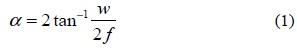
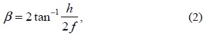
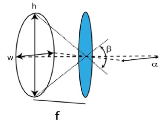
The viewing angle is an important feature of any 3D visualization system because it establishes the range of positions from the display in which a viewer can observe the 3D reconstruction. In an InI monitor, the collection of microimages is projected onto the high-resolution display and the microlens array is placed in front of it, so that every microimage in under one microlens. The best visualization is obtained when the microimages are set at the focal plane of the microlenses (see 0). Then, from this figure, we can easily obtain the horizontal (α) and vertical (β) viewing angles of the 3D reconstruction. Their expressions are as follows:

and

where w denotes the width of the microimage,
In this section, we will explain the method proposed for the enlargement of the viewing angle of InI monitors. First, we will vriefly explain the two ideas already reported (Miura et al.'s method [10] and SOPC 20.[5]). Second, we will show that a proper fusion of the concepts of these two methods leads to the development of a new and effective mehod for increasing the viewing angle.
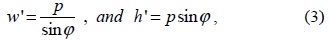
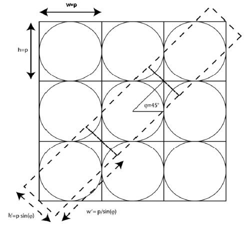
The basic idea of Miura et al. [10] involves changing the size of the EIs by increasing their width while decreasing the height, keeping invariant the total number of pixels. To do so, the researchers tiled the microlens array in the capture and reconstruction processe. The overlapping issue in the capture stage was solved by inserting an aperture stop in the capture system. Following this architecture, the size of the EIs and the viewing angles were properly modified. In 0, the effect of tilting a microlens array, with a square arrangement, is shown. In this configuration, the size of the EIs are calculated using Eq. (3),

whereas th viewing angle of the enlarged Eis is expressed as follows:
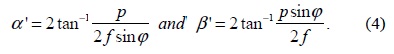
In the above equations,
We reported a method called SPOC 2.0 that can be used to solve this type of problems [5]. Basically, SPOC 2.0 takes advantage of three facts: 1) the flexibility that InI offers in the capture process, 2) the possibility of obtaining an equivalent plenoptic image from an integral image [5,15], and 3) the fact that a plenoptic image can be easily projected into a display. The last fact enables the projection of an InI image by transforming it into a plenoptic image already adapted to the chosen microlens array and display. Therefore, SPOC 2.0 provides the freedom to perform the capture process and, additionally, adapts InI to any given display and any given microlenses. Besides, the images obtained are already orthoscopic and we can chose, with some degree of freedom, the reference plane and the field of view of the scene.
The characteristics of the integral image determine the characteristics of the equivalent plenoptic image. For example, the number of elemental images in an integral image fixes the pixels per microimage of the equivalent plenoptic image. In addition, the number of pixels of any elemental image determines the microimage count of the equivalent plenoptic image. However, there is another question to account for: does the spatial configuration of the pixels within any elemental image determine the distribution of the microimages centers? Note that in order to build a microimage, the same pixel from any EI is mapped taking into account its relative position in the integral image. Therefore, the first pixel of every EI corresponds to the first microimage. Then, we can assume that every pixel in the EI relates with one microimage, and therefore, the relative position of the pixels in an EI determines the distribution of microlenses. For example, in a normal camera, the pixels are distributed in a rectangular grid, and therefore, the microimage distribution will be equivalent. However, if the pixels in the EIs were distributed in a hexagonal grid, the equivalent microimages would be rearranged following a hexagonal pattern. Therefore, we can obtain a hexagonal microimage distribution from EIs with a hexagonal pixel distribution. This can be easily obtained with a normal camera just by resizing or averaging pixels because of the fact that the EIs captured with the synthetic aperture method have more pixels than required, permitting considerable flexibility in the adapting process.
The proposed method is based on combining the concepts behind the two previously described methods. Our goal is the generation of a plenoptic image with an enlarged viewing angle that can be projected into any InI monitor by using any microlenses for 3D visualization.
As stated before, from an integral image, we can obtain an equivalent plenoptic image. To reproduce Miura et al.’s enlarged EIs, we need to obtain a plenoptic image with asymmetric microimages arranged in a hexagonal distribution. Therefore, the integral image captured has to have an asymmetric number of photographs in which the EIs have a hexagonal pixel distribution. The equivalent microimage size and distribution of the plenoptic image depend on the tilted microlens array that will be used in the visualization stage. Taking this into account, we proceed to describe the steps needed to produce plenoptic images with an enlarged viewing angle.
First, the display and the microlenses that are going to be used in the 3D reconstruction must be chosen. Second, the number of pixels of the selected display that will form a microimage, which has the same size of a microlens of the chosen array, is calculated. This will be the size in pixels of a microimage of the standard projected plenoptic image. Third, we decide the tilting angle of the microlenses, we can determine the increase in the viewing angle. Note that, because of the overlapping of the microimages, not all rotating angles are valid [11]. Fourth, we calculate the new size in pixels, using Eq. (2) in the case of a rectangular microlens array, of the microimages after tilting the microlens array. This will be the size in pixels of one microimage of the enlarged view plenoptic image. Fifth, the integral image of the 3D scene, with the number of EIs equal to the number of pixels per microimage of the standard plenoptic image, is captured. Sixth, another integral image with the number of EIs equal to the number of pixels per microimage of the enlarged view plenoptic image is captured. Seventh, we transform the two integral images into plenoptics images by applying SPOC 2.0, but resizing the EIs of the enlarged view case so that they have a hexagonal distribution and taking into account that the final plenoptic image has to have a hexagonal microimage distribution. Eighth, resize both images so that each has the correct number of pixels per microimage. Ninth, project the images onto the display.
In order to test our proposal, we capture two integral images, transform them into plenoptic images, and finally project them onto a display. While one of the plenoptic images is a standard image, with square microimages (the same number of pixels in the x and y directions), the other has an enlarged horizontal viewing angle, with rectangular microimages (with the width of the EI greater than the height). Both captures are performed following the classic synthetic aperture method: shifting the position of the camera per shot [16].
For the display process, we used a rectangular microlens array with focal length
In our method, the tilt angle for the enlarge case is
The integral image is recorded using a Canon 450 D with an objective focal length of 18 mm, focused at the infinitum. The photographs have a resolution of 4272 × 2848 pixels. The whole 3D scene is captured by moving the camera with a pair of motors. The camera moves in the (
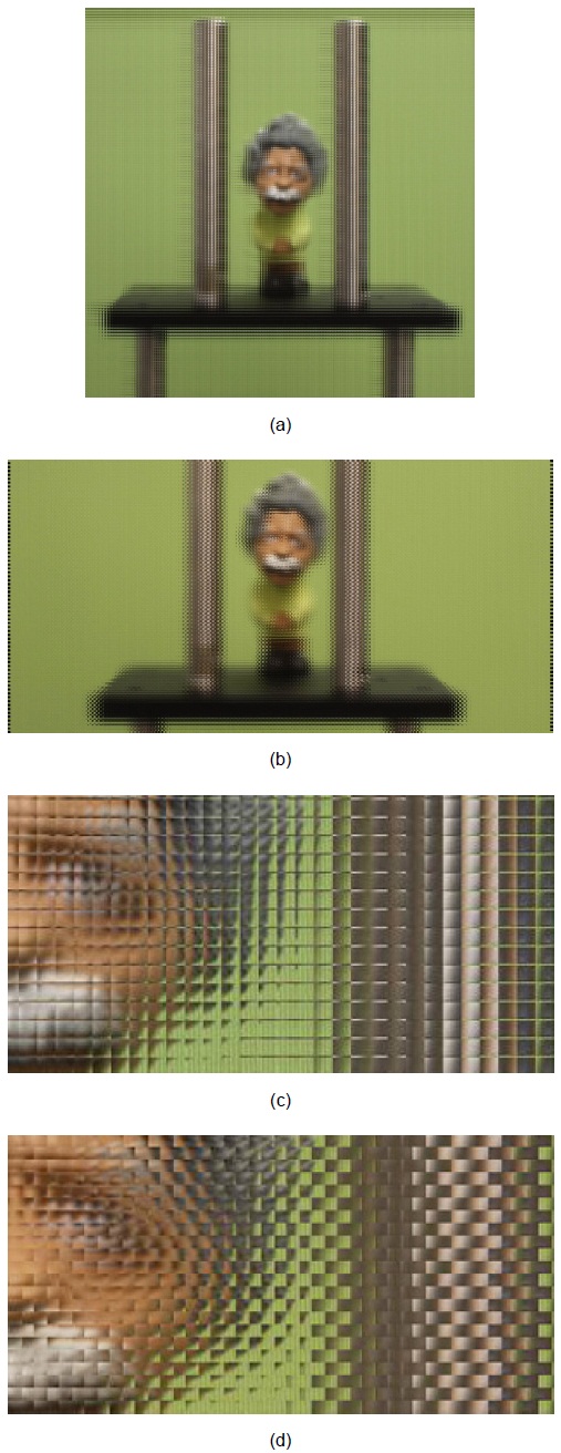
To obtain the correct microimages for both images, the number of photos captured should be equal to the number of pixels per microimage. However, as these values must be integers, for the standard image, 11 × 11 photographs are recorded, and for the enlarged view case, we capture 15 × 8 photographs. To these experimental photographs, SPOC 2.0 is applied. Both images are processed to obtain 139 × 139 microimages for each. After the transformation, both plenoptic images are resized in order to match the correct dimensions of the microimages. The final images are shown in Fig. 3.
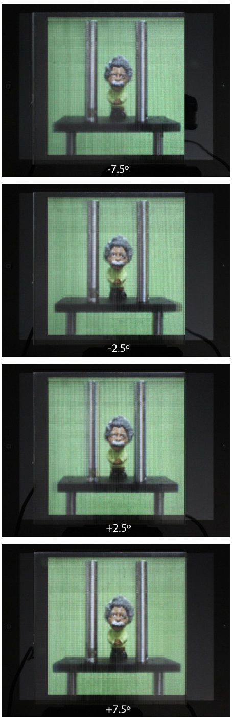
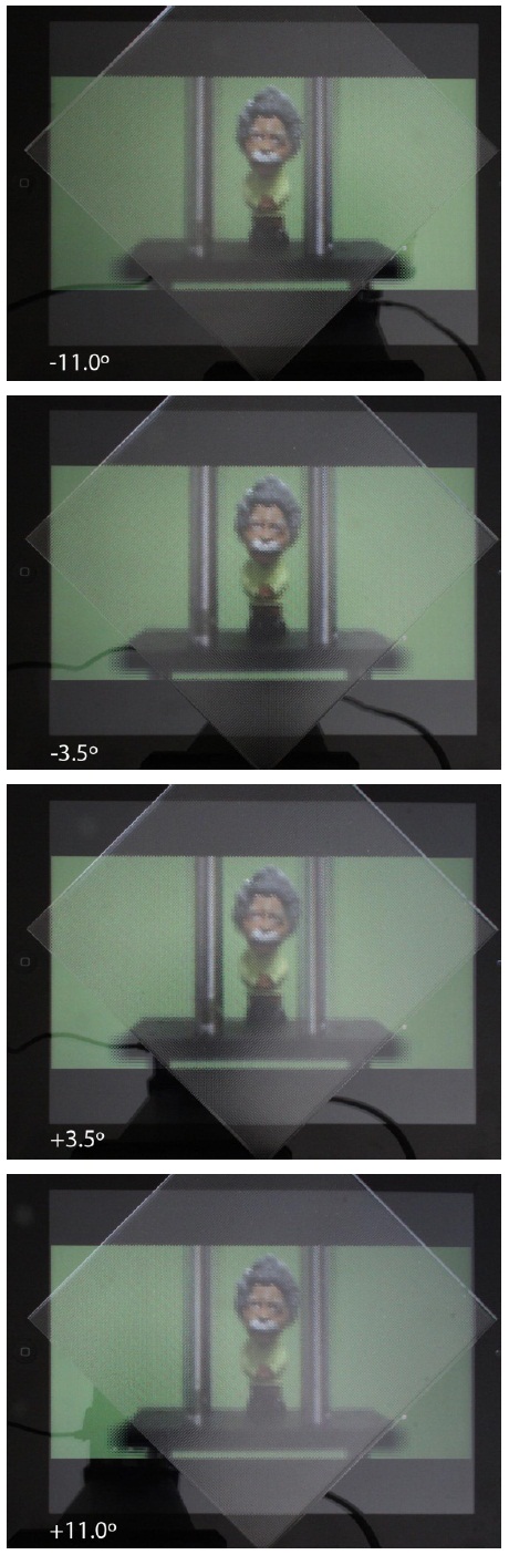
To show the increase in the viewing angle, we recorded a series of photographs simulating the head movement of an observer visualizing the projected images. The distance between neighboring photographs corresponded to an angular difference of 0.5°. We found a viewing angle of 15° for the standard image and 22° for the enlarged image, see Figs. 4 and 5.
Although it is clear that the viewing angle is increased, we are interested in comparing the experimental value with the theoretical one. Using Eq. (3), we obtain the theoretical values of 17.23° and 24.19° for the normal and enlarged view cases, respectively. Obviously, there is some discrepancy between the theoretical and experimental values. This discrepancy can be attributed to the fact that Eq. (3) is obtained assuming that the microimages are placed at the focal plane of the microlenses. Experimentally, this condition is not fulfilled because of the existence of a plate protecting the pixels in the iPad, making it impossible to place the image at the focal plane of the microlens array.
To check whether this measured discrepancy is really produced because of the crystal layer, another measurement of the viewing angle is conducted. In this experiment, the standard plenoptic image was printed on photographic paper and placed at the focal distance of the microlenses. For this case, the measured viewing angle is 17.5° ± 0.5°, very close to the theoretical value within the experimental error. From this result, we can conclude that the measured discrepancy in the viewing angle for the standard and the enlarged view plenoptic images is principally due to the crystal layer of the iPad.
We have reported a new algorithm for the calculation of microimages, with an enlarged viewing angle, which can be projected on an InI monitor. We have presented experimental results proving this algorithm. Our algorithm is an improved version of SPOC 2.0, which adds the idea of reshaping the EIs to increase the viewing angle.