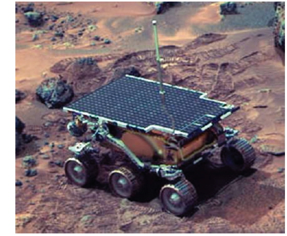
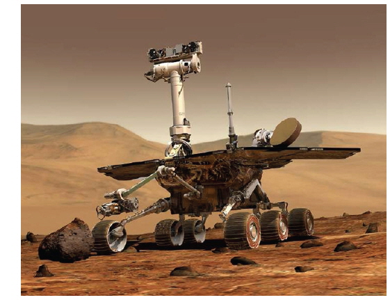
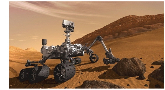
Planetary exploration rovers travel a road of unknown surfaces to the destination and perform scientific missions, such as, the investigation of geology and climate, the investigation of the existence of water and alien life forms (http://science.nasa.gov/platenary-science/missions). In order to perform these scientific missions successfully, the rover is developed to ensure the design targets: survival through the mission period and stability of movement to the destination (Eisen 1997, Siegwart et al. 2002, Chen et al. 2009). The typical suspensions applied to a conventional rover is a rocker-bogie suspension developed by NASA in 1960s ~ 1970s (Eom et al. 2012a). This suspension was developed for a slowmoving system and 6-wheel application is enabled through this suspension structure. The rocker-bogie suspension undergoes a passive transformation in response to the shape of surfaces. Also it enables slope-climbing of 30 degree-tilt, and it is possible to maintain static equilibrium at the slope of 40 degree-tilt. The suspension of rocker-bogie type was applied to the first Mars Exploration Rover, Sojouner to prove its superior driving performance as shown in Fig. 1 through Fig. 3. It was subsequently applied to Spirit/Opportunity (http://marsrover.nasa.gov/home/index.html) and Curiosity (http://mars.jpl.nasa.gov/msl) (Bajracharya 2008, Eom et al. 2012a). Also at present, in addition to USA, developed nations in space technologies, such as, Europe, China, and Japan, etc., have had research projects on the suspension system of a rover lead by government funded research institutes and universities (Seeni et al. 2010, Ding et al. 2011, Trease et al. 2011).
Rovers have sensors to detect obstacles or dangers in forward or backward directions to get to the destination safely. The sensor collects the data of obstacles, such as, height, width, etc., in its way. The rover analyzes the obtained data to evaluate the possibility of stepping over the obstacle, and when it seems efficient in driving stability and power consumption to step over than to circumvent the obstacle, the rover goes on to overcome the obstacle. Therefore, in order to take account of the driving stability and power management at the same time, it is essential to have a suspension design to enable the efficient overcoming of obstacles (Kim et al. 2009, Eom et al. 2012b, Eom et al. 2014).
In this study, an 8-wheel suspension is designed to enable efficient climbing of slopes on a passage to the destination considering the pivot location to evaluate the climbing performance. In Section 2, the moment at the pivot connecting the two front wheels of a rover is derived, and in Section 3, in order to compare the hill-climbing performance, a test experiment is performed to compare the magnitude of moment according to the change in the tilt angle and the position of the pivot and the results are described. Finally, conclusion is summarized in the last section.
2. DYNAMIC MODELING OF MOMENT ON PIVOT
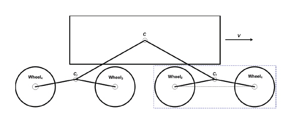
In this section, a conceptual outline is described and the necessary parameters are defined, for the proposed suspension. Also, the dynamic modeling on the above mentioned moment which arises during hill-climbing process is described. The outline of the 8-wheel suspension for a planetary exploration rover is shown in Fig. 4. The target of dynamic modeling is the center of rotation (the pivot;
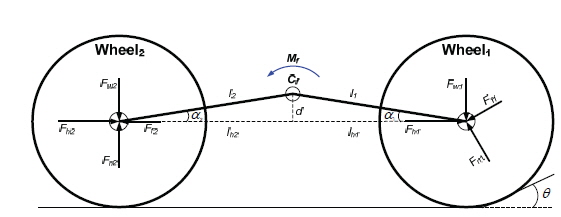
For an 8-wheeled rover whose suspension system responds passively against tilted surfaces, the two front wheels’ movement is divided into 4 stages as follows during the driving transition from flat surfaces to tilted surfaces. First, all wheels are on the flat surface and Wheel 1 touches the tilted surface to begin climbing the slope. Secondly, Wheel 1 is on the tilted surface and the Wheel 2 is on the flat surface. Thirdly, Wheel 1 is on the tilted surface and Wheel 2 begins climbing the slopes. Finally, both wheels are on the tilted surface to climb the slopes. Among the four stages, the first stage at which the moment start to arise at the pivot is described in this study. The Free Body Diagram (FBD) to derive the moment at the pivot is shown in Fig. 5.
Where,
For ground moving robots, in order to identify the position of a robot, dynamics is derived considering the slipping effect between the wheel and the surface (Kozlowski & Pazderski 2004), however, for planetary exploration rovers, since the sensor type and the methodology of position identification are different from those of ground moving robots, thus, this effect was deemed to be negligible. Moreover, due to the planetary surface environment which consists of irregular particles with various granularities, the friction coefficient term between the wheel and the surface is considered in the design of rover wheels, it is assumed to be same for the simplicity of equations.
From the FBD of Fig. 5, the derivation process of moment (

where, , , , .

where, , , , .

where, ,

where, ,

The larger the moment (
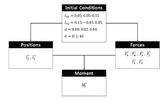
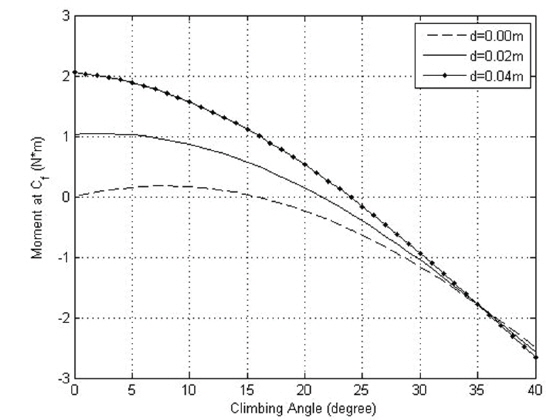
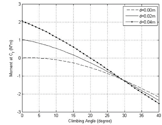
Since the purpose of test experiment is to compare the hill-climbing performance according to the change in the position of pivot under the same driving environment, the effect of wheel slipping is neglected and same friction coefficients are assumed in this experiment. The tilted angle of slope is varied from 0° to 40° by 1°. While rovers are designed to be capable of climbing the slopes of maximum 30° tilt in general (Eom et al. 2012a), the test condition was established considering the requirement to maintain static equilibrium at the slope of 40°. The properties of proposed suspension are summarized in Table 1. For simulations, the flowchart of the moment derivation process using force and position vectors defined in the FBD is shown in Fig. 6. Fig. 7 through Fig. 9 show the moment values (
[Table 1.] Properties about the proposed suspension.
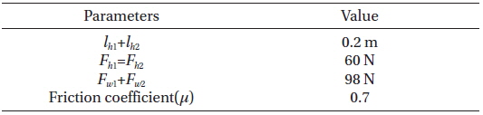
Properties about the proposed suspension.
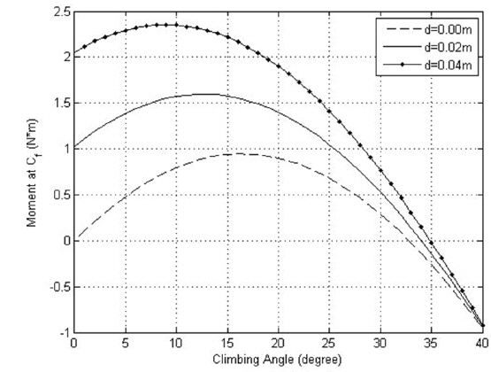
Fig. 8 shows the behavior of the moment values when
Fig. 9 displays the behavior of the moment values when
In this study, for a planetary exploration rover which is required to overcome the obstacles in its way to the destination, a suspension design to improve the hill-climbing performance is proposed. The moment at the pivot which connects the two front wheels was derived for the proposed suspension system, and the change in the moment values were compared varying the vertical and horizon distance of the pivot according to the change in tilt angle.
According to the result of test experiment, as the pivot position is higher against the mid-point of horizontal line which connects the two front wheels and the pivot position is horizontally closer to the second wheel, hill-climbing performance is improved. However, it is not sufficient to analyze the complete hill-climbing performance by the analysis of hill-climbing at the inception of slope, dynamic modeling for the whole hill-climbing process and simulation will be performed to verify the excellence of current design for further study.