Machine vision plays an important role in the automation of a large number of industrial processes. Automation using 3-D vision systems that corroborate 3-D information on objects can be widely deployed in automated inspection systems. A key step in the process of inspection is the extraction of the 3-D shape of the inspected surface. For example, surface inspection of printed circuit boards and solder joints are among the many industrial tasks that can be visually automated and that are laborious for humans to perform.
The reflection of light from an object, depending on the surface-air interface, can be approximately divided into specular reflection and diffuse reflection [1]. A mirror-like reflection in a mirror, metal, or glass whose surface is smooth and glossy is called specular reflection. The surfaces of polished metal parts, gold bumps, and solder joints are practical examples of specular surfaces, at which a high percent of light is reflected such that the angle of incidence equals the angle of reflection [2, 3].
Research on analyzing the shape of specular reflectors has been relatively neglected, since most objects largely exhibit diffuse reflection. There has been some effort to measure the 3-D shapes of objects with specular reflection using optical methods such as laser scanning [4]. Triangulation-based light striping methods have been also widely used for 3-D shape measurements, although these also are difficult to apply to specular objects [5]. Other methods include [6, 7] where image acquisition was conducted using an optimized combination of lighting and camera. In the electronics industry, the inspection of solder joints using structured illumination such as light stripes [8-10] or more complex light patterns [11] is common.
In this paper, we describe a new method for estimating the 3-D shape of specular objects, where a vision system is composed of a CCD camera and an illumination that consists of spatially arranged point lights. The reflected image of the illumination is acquired and processed to estimate the 3-D shape of the reflecting surface, after comparing with the acquired image for a flat specular reflector such as a mirror. To this end, the optical path from the light source to the image sensor, including reflector and lens, is drawn. We analyze how the positions of the light points in the captured image are affected by variations in the height and slope of the reflecting surface, which information is used to estimate 3-D shape. In the experiments, a machine vision system is implemented and image acquisition of several relevant sample objects is conducted, showing that the estimation of 3-D shape is performed effectively by the proposed method.
II. ANALYSIS OF THE OPTICAL PATH OF THE REFLECTIVE SURFACE MIRROR REFLECTOR
In order to understand our proposed method of estimating the 3-D shapes of objects with specular reflective surfaces, consider point sources of light, as from stars reflected from the surface of a body of water. If we observe the lights reflected on a calm surface of water, they should be at fixed positions. If the surface of water is perturbed by the wind, the reflecting surface will change its shape, resulting in a change in the positions of the light reflections. Indeed, measurements of variations of the relative positions of the reflected lights might make it possible to estimate the surface shape of the water. By applying this idea to objects with specular reflection, the measured positions of light reflected from a specular surface can be used to estimate the 3-D shape of the surface. A collection of point source lights is used for illumination, and the position of each point is measured to calculate 3-D shape. In our experiments, spatially distributed point source lights, such as LEDs, were reflected from the specular surfaces, creating images captured by a CCD camera. For each point, the deviations from the reference positions, where the points would be located for the case of a perfectly flat reflector were calculated. A convex and a concave mirror were used as specular objects, but an analysis of the optical path of the light from each point light source to the CCD image sensor for a specular object having a general shape will be described.
The optical path of the reflected light, as shown in Fig. 1, varies according to the slope and the displacement of the reflecting surface of the object in numerous ways.
Consider the path of light generated from point A and reflected from the specular surface. It travels toward the camera as shown in Fig. 1. Then three cases are possible: (a) only the height of the reflecting surface changed (b) only the slope of the surface changed (c) both the height and slope changed. In all three cases, the light is incident on the camera sensor at the same incident angle, so point A would be at the same location in the acquired images. Hence, for surfaces of arbitrary shape, it is impossible to obtain 3-D information from a single acquired image, which is often referred as height-slope ambiguity.
To analyze the optical path of the reflected light, first, let us consider the optical path of light emitted from a point light source and reflected from a specular surface and to the camera sensor through a lens. The light path for the reflection from a flat surface is drawn in Fig. 2.
Figure 2 shows the path of light, starting from point A, reflected at point B on the surface, running through the camera lens at an incident angle of

where tan
Figure 2 also shows how the optical path is changed when the height of the reflecting surface is varied. In Fig. 2, when the reflecting point on the surface moves from B to B' with displacement Z, the light passes through the lens at an angle other than

where tan
We can combine (1) and (2):

The displacement

Next, we consider the change in the optical path as the slope of the reflecting surface varies. As shown in Fig. 3, let the slope at point B'' on the reflecting surface deviate by angle
Now assuming that the light from point A be reflected and pass through the lens at an incident angle

where tan

The last term of the right hand side of (6) can be rewritten:

and also

which means that we can find how much the slope of the reflecting surface deviates.
The analysis of the optical path above was done under the assumption that, either the height or slope of the reflecting surface varied (but not both) and using the simple principle that the angle of incidence and reflection are the same. However, on a typical 3-D shape, there are variations in the height or slope of the surface, so the optical path can be very complicated.
When the height and slope of the reflecting surface vary at the same time, then (2) and (5) can be combined:

where tan


As shown in equations (10) and (11), there are infinite choices
Thus, we use an approximation which assumes that the object has a smoothly varying surface. Figure 4 depicts some examples of possible estimated 3-D shapes of curved surfaces. Three cases are shown: (a) a displacement of the reflecting surface under the assumption that only the height varied (b) a deviation of the slope of the surface under the assumption that the slope of the reflecting surface deviated (c) a change in the height and the slope of the surface under the assumption that both of height and the slope changed. In case (b), it should be impossible that the shape of a surface has a deviating slope without any change in height. In case (a), only the height of the surface changes without any change of slope. The gold bump on a semiconductor package should be a good example of such a shape. Although case (c) would occur most commonly, it would be difficult to estimate the height and slope of specular surfaces having general shape as in case (c).
There are infinite solutions which satisfy (11); that is, the possible displacements
To understand the method in the 3-D manner as in the experiments,
As the first step in the proposed method, a reference point should be selected. The reference point on the reflecting surface is the point where it assumed that no displacement in height and no deviation in the slope of the reflecting surface occurs. Usually, the most protruding point on a convex surface can make a good reference point. Next, the displacements of the heights of the surface can be calculated by (4) for the neighboring points. By use of these displacements, the slope deviation of the surface can be obtained by (11). These approximate the slopes at neighboring points in the direction away from the reference point. The total displacement at these points can be calculated by (11). These known slopes are also used to obtain the height differences caused by slopes between adjacent points and can be easily calculated. The displacements in the curved surface can be obtained by subtracting these differences from the total displacements. The displacements are again used to obtain the slopes at neighboring points. By propagating the computation from the reference point, the 3-D shape of the overall convex reflecting surface is estimated. While the approximation errs to some degree, the approach should improve on results estimated under the assumption that only the height will vary.
To reproduce easily the method, the procedure can be depicted by the diagram in Fig. 5.
III. EXPERIMENTS FOR ESTIMATION OF 3-D SHAPE OF SPECULAR REFLECTOR
To estimate 3-D shapes with specular reflections, an experimental system to capture images is necessary. It is represented as a simple configuration in Fig. 6, where the actual experimental device is shown. In the experiment, light from the light source is reflected from the specular reflector. Because most of the light is reflected in only one direction, illumination does not require a significant amount of light intensity [12]. In the experiment, a 7-inch notebook display having a 1024×600 pixel resolution was used instead of an LED light and an Edmund Optics’ EO-3112C camera was used, having 1/2 inch CCD sensor with 2048×1536 pixels. The images obtained from the camera were transferred via USB at a rate of 15 fps. In the optical system configuration, the distances from the center of the reflector to the illumination and to the lens were 200 mm and 150 mm, respectively.
We used readily available convex and concave mirrors to serve as specular reflectors in the experiment. The actual measurements of the 3-D shapes of the mirror surfaces were carried out to compare with the results estimated by the proposed method. A Mitutoyo MACH-V9106 measurement device was used in the experiment. The 3-D shapes were measured at intervals of 5 mm horizontally and vertically, and selected measurements corresponding to the locations of point lights were determined by interpolation as shown in Table 1 below. In addition, the measurements shown in Table 1 yielded a 3-D graph as provided in Fig. 7.
[TABLE 1.] Result of 3-D measurements (unit: mm)

Result of 3-D measurements (unit: mm)
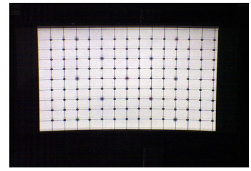
The image that was used for illumination contains evenly distributed 10 pixel diameter circles of brightness. The acquired image reflected from a flat highly specular mirror is shown in Fig. 8, while Fig. 9 shows the acquired image for a convex mirror.
The acquired images in Fig. 8 and Fig. 9 show the camera’s geometric distortion due to an inclined optical configuration, which was compensated for by using a simple look-up table. After fixing the optical configuration so that the reference point is located at the center of the acquired image, the relative positions in the image were calculated for each light point. From the acquired images, it can be observed that the light points become more deviated from their original positions with increased distance from the reference point; that is, the bigger the
We wrote a MATLAB program where, for simplicity, the centroid of each point was regarded as its position in the acquired image. First, the geometric distortion due to the configuration was compensated for, then each point light was isolated from the background by binarization using a threshold. Geometric clustering was applied using morphological filters to distinguish each point and, for each cluster, the centroid was calculated [13]. Using the distribution of centroids of the points in the image of a flat mirror, the relative displacements of the centroids for convex or concave mirror were calculated and used for 3-D shape estimation. For a total number of 126 points arrayed in 9 rows by 14 columns, the calculated displacement of the positions in the acquired image are shown in Table 2.
[TABLE 2.] Displacement of position for each point light (in pixels)

Displacement of position for each point light (in pixels)
Next, using the formula described in the previous chapter, the variation in the height at each point was estimated. At the reference point, which is at row 7 and column 5 in the acquired image, the height was calculated under the assumption that only the height varied. This approximate height was used to estimate the slope at neighboring points and used again with the estimated slope to calculate the height of these neighboring points. Propagating the computation in all direction from the reference point yielded results for the entire surface as shown in Table 3 and Fig. 10.
[TABLE 3.] Estimated heights of surface by proposed method (unit: mm)
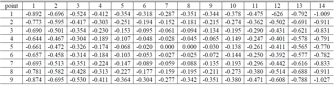
Estimated heights of surface by proposed method (unit: mm)
The resulting estimated surface using our proposed method contained some differences relative to the measurements. For the convex mirror used in the experiment, the maximum error was 18.2%, while the maximum error was 11% for the concave mirror. Although the accuracy is not yet adequate as an inspection criterion, the proposed method shows that it is possible to obtain 3-D shape information with reasonable accuracy. Conversely, using only the optical path analysis without approximation suggests a limitation in the case where only the height of surface is changed. The estimated 3-D shape under the assumption that only the height of surface changes is shown in Table 4 and Fig. 11.
[TABLE 4.] Estimated heights of surface under height assumption (unit: mm)
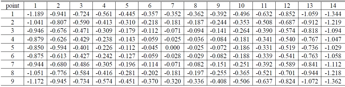
Estimated heights of surface under height assumption (unit: mm)
Considering the results obtained under the assumption that only the height of the surface varied, the estimated heights of the surface are somewhat exaggerated. This follows since the change in the optical path from variation of the slope of the surface is incorrectly attributed to variation in the surface height. For the convex object used in the experiment, the maximum error was 51.2%, which is not of use. The horizontal parts of 3 results are shown in Fig. 12, which are the ground truth shape measurement, the estimated shape via the proposed method and the estimate obtained by optical path analysis. Clearly, the proposed method can estimate more accurate 3-D shape than estimation by the optical path analysis. Approximately 1/3 of the error was reduced in the convex mirror example used in the experiment.
We explained a new method to estimate the 3-D shape of a specular reflector. To develop the proposed method, we analyzed how the positions of point light sources in a captured image are affected by variations in the height and slope of a reflecting surface. Experiments were conducted using a CCD camera and multi-point illumination. The results indicate that the method can achieve reasonable estimates of the height and slope of a reflecting surface. Also it was shown that approximately 1/3 of the error was reduced in the convex mirror used in the experiment.
The specular objects used in experiments are too simple to evaluate the effectiveness of the proposed method. Although the method could be generalized by segmenting the surface into concave and convex areas for arbitrary smooth surfaces, further research works should be needed to divide a surface into the areas where the 3-D shape can be approximately estimated without discontinuity at boundaries and to set the reference point for each segmented concave or convex plane. Also it would be necessary to expand the method to more complicated shape and to improve accuracy by increasing the number of point light sources.