Spectrum-sliced wavelength-division-multiplexed passive optical network (WDM-PON) is regarded as a promising candidate for access networks [1-3]. The spectrum-sliced incoherent light channels generated from a broadband light source (BLS) have helped to replace the expensive laser diodes in optical subscriber systems. However, the spontaneous-spontaneous beat noise becomes dominant in optical receivers [4-6] and the high relative intensity noise (RIN) of spectrum sliced channels restricts the data bandwidth.
Some techniques have been implemented for the suppression of RIN in spectrum-sliced channels. A Four Wave Mixing (FWM) method [7] has been previously used to circumvent the problem of RIN. The FWM method belongs to an optical method that increases the optical bandwidth of the received spectrum-sliced channel within an optical receiver, thereby reducing the RIN. But this method requires a high optical power and a dispersion shifted fiber for each received channel. Reflective semiconductor optical amplifiers (RSOAs) provide polarization-insensitive modulations and suppress the RIN noise up to a few GHz [8, 9]. Using RSOAs, 100-GHz [10] and 50-GHz [11] spaced spectrum-sliced WDM PONs have been demonstrated.
In this paper, we use polarization-independent optical modulators (PIOMs) to suppress the RIN of spectrum-sliced channels. The PIOM evenly redistributes optical frequency components in spectral domain and reduces the RIN. It can be used at the broadband light source (BLS) output to produce spectrum-sliced channels having lower RIN values. Also, it can be used for each spectrum-sliced channel at each optical network unit (ONU).
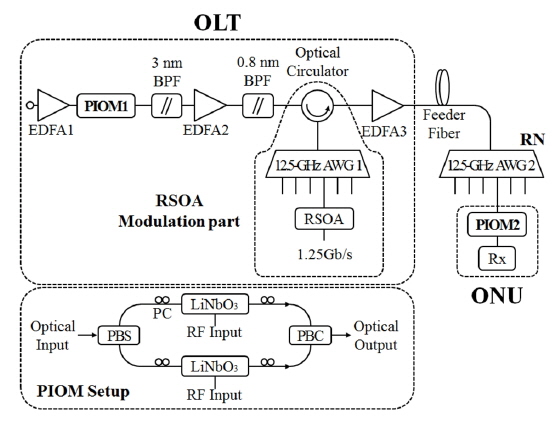
Figure 1 shows our experimental setup to demonstrate the RIN suppression in a 12.5-GHz spaced spectrum-sliced WDM PON for the downstream direction. We chose the 12.5 GHz as the channel spacing since the PIOM effects increase as the channel bandwidth decreases. The first erbium-doped fiber amplifier (EDFA1), used as a BLS, produced an amplified spontaneous emission (ASE) at 24 dBm. We further used a 3 nm filter and an EDFA, EDFA2, to increase the optical power before the spectrum slicing. The ASE from the EDFA1 was spectrum sliced using a 12.5-GHz arrayed waveguide grating (AWG), AWG1. The AWG1 was a 1 × 8 Gaussian type having a loss of 5 dB. The AWG1 had a free spectral range of 200 GHz, which means that the transmission peak of each AWG1 port repeats in 200 GHz period. In our experiment, we focused on a single spectrum-sliced channel centered at 1549.6 nm. Thus we used a 0.8 nm filter before the AWG1. This channel was modulated using an RSOA as is shown in Fig. 1. The injection power to the RSOA was about -13 dBm. The channel was modulated in 1.25 Gb/s speed. We used a 27-1 pseudorandom bit sequence for the modulation. The 3-dB bandwidth of the transmitted spectrum-sliced channel was about 0.07 nm and the extinction ratio (ER) was maintained as 3.5 dB for the wavelength reuse [12, 13]. This agrees with the typical ER values for the wavelength reuse, 2 ~ 5 dB [12, 13]. The modulated channel was then transmitted to the remote node (RN) using a feeder fiber. The length of the feeder fiber was varied from 0 to 75 km. The feeder fiber was a conventional single mode fiber. We used another 12.5-GHz AWG at RN, AWG2, to demultiplex the transmitted channel. The demultiplexed channel was sent to the ONU to be converted to an electrical signal.
We tested two possible locations of the PIOM. The first PIOM, PIOM1, was located at the output of the EDFA1. The second PIOM, PIOM2, was located within the ONU. Single PIOM was made of a polarization beam splitter (PBS), a polarization beam combiner (PBC), and two LiNbO3 Mach-Zehnder modulators in between [14]. The PBS splits the two orthogonal polarization components of the optical input. Each polarization component is modulated sinusoidally using a LiNbO3 Mach-Zehnder modulator. The modulated lights are combined using the PBC. The modulators were driven with a 12.5-GHz radio frequency (RF) signal of 38 dBm (50 Vp-p). Since only one PIOM was available to us, the PIOM1 and the PIOM2 were operated separately. The PIOM had a loss about 20 dB.
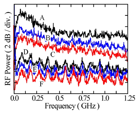
Figure 2 shows the RF spectra measured within the ONU using a 7-GHz photo-detector. The figure compares the RIN suppression capabilities of PIOMs and the RSOA. The feeder fiber length is zero km. The curves A, B, and C are obtained without the RSOA modulation part in Fig 1. In this case, the output of the 0.8 nm band pass filter is directly connected to the EDFA3. The curves D, E, and F are obtained with the RSOA modulation part. The curves A and D are obtained without using the PIOMs. The curves B and E are obtained using the PIOM1. The curves C and F are obtained using the PIOM2. In all cases, the optical power to the photo-detector is -11 dBm. The RSOA input current is 20 mA and the output power of the RSOA is -4 dBm. No RF signal is applied to the RSOA during the measurements. All the PIOMs and the RSOA reduce the RIN. Although the RSOA performs the best, the use of RSOA with PIOMs gives better results. The PIOM2 performance exceeds that of the PIOM1, which does not increase the channel bandwidth.
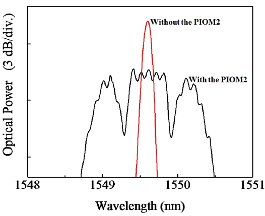
Figure 3 shows the optical spectra of a spectrum-sliced channel measured at the ONU with and without the PIOM2. The feeder fiber length is zero km. With the PIOM2, the 3-dB bandwidth of the received spectrum-sliced channel broadens from 0.07 to 1.5 nm.
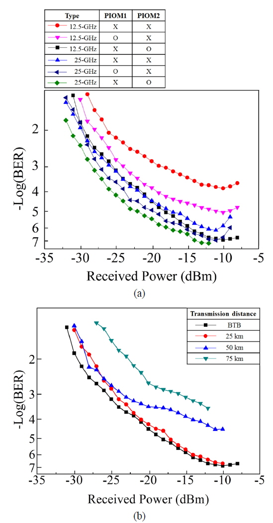
Figure 4 (a) compares the BER curves using the PIOMs. As a reference, the BER curve for a 25-GHz spaced spectrum-sliced channel is also shown that is obtained using 25-GHz AWGs in the same way as Fig. 1. With the PIOM1, the minimum BER improves by more than one order of magnitude from 1.4 × 10⁻⁴ to 9.2 × 10⁻⁶. With the PIOM2, the minimum BER improves by 3 orders of magnitude approximately, from 1.4 × 10⁻⁴ to 1.5 × 10⁻⁷. When the 25-GHz-spaced spectrum-sliced channels are used in 1-GbE speed, the use of PIOM1 reduces the BER of the spectrum-sliced channel by less than one order of magnitude, from 7.9 × 10⁻⁷ to 1.4 × 10⁻⁷. The use of PIOM2 within the ONU reduces the BER by about one order of magnitude, from 7.9 × 10⁻⁷ to 8.3 × 10⁻⁸. Thus the PIOMs are more effective for 12.5-GHz spaced channels. Figure 4 (b) shows the BER curve changes when the feeder fiber length is increased from 0 to 75 km with the PIOM2. The BER curve after the 25-km transmission shows negligible changes from the back-to-back result. However, the minimum BER increases rapidly afterwards, which means the effects of the PIOM2 diminish as the fiber dispersion affects the optical channel.
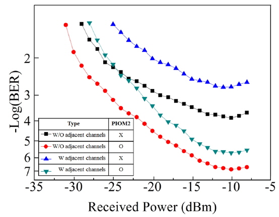
Until now, we have neglected the cross talks from adjacent channels. In Fig. 5, we show the effects from two adjacent channels on the central channel’s BER measured with and without the PIOM2. The central channel is still centered at 1549.6 nm. The adjacent channels are modulated using a semiconductor amplifier and injected to the 12.5-GHz AWG2 using a 3-dB fiber coupler. The minimum BER value for the central channel with the adjacent channels is 1.8 × 10⁻³. This value is measured without the PIOM2. Using the PIOM2, the minimum BER is improved to 2.1 × 10⁻⁶ almost by 4 orders of magnitude. Thus the improvement by the PIOM2 is enhanced when there are adjacent channels.
The PIOM use in our experiment has a high cost, and it is difficult to use it within the ONU in its present form. But it can be used within the OLT since its benefit can be shared by all subscribers. The PIOM can be used within the ONU also when the PIOM is realized cheaply using polarization-independent silicon [15] or polymer photonic modulators [16]. The bandwidth of the high power RF amplifiers is not necessarily wide and their prices can be made cheap through mass production.
The packet loss rate (PLR) for 1 GbE can be related with the BER using an Ethernet analyzer. The PLR is 1 % when the BER is 5.3 × 10⁻⁴ and is around 10-4 for BER = 10-8. Our 12.5-GHz spectrum-sliced WDM PON using the PIOM also meets the PLR criterion for real time services, 5 ~ 10% [17].
We have demonstrated the usefulness of PIOMs for spectrum-sliced incoherent channels especially for the 25-GHz and the 12.5-GHz spaced channels. The PIOM has been used after the BLS or within the ONU. Although the former shows smaller BER enhancements than the latter, its benefit can be shared by all subscribers. The PIOM can be realized cheaply using polarization-independent silicon or polymer photonic modulators.