검색 전체 메뉴
PDF
맨 위로
OA 학술지
Rigorous Analysis on Ring-Doped-Core Fibers for Generating Cylindrical Vector Beams
  • 비영리 CC BY-NC
  • 비영리 CC BY-NC
ABSTRACT
Rigorous Analysis on Ring-Doped-Core Fibers for Generating Cylindrical Vector Beams
KEYWORD
Cylindrical vector beam , Fiber laser , Ring-doped core fiber , Laser threshold , Overlap factor
  • I. INTRODUCTION

    Cylindrical vector beams (CVBs) have recently been receiving a considerable amount of research attention because of their unique and interesting capability of carrying orbital angular momentum [1]. In particular, CVBs can offer highly focused beam spots as well as dipole-like oscillating field patterns [2-6], which can open up opportunities for novel applications, such as optical trapping [2], microscopy [3, 4], plasmonic focusing [5], high-precision laser machining [6], etc.

    To date there have been a variety of studies on generating CVBs mostly in free space, utilizing special optical components [7-11], such as prisms, crystals, polarizers, lenses, axicons, retarders, etc., or using a beam-combining technique [12]. Other studies are related with the CVB generation utilizing novel types of passive optical fibers, which include a coupling scheme to launch CVBs into a fiber by placing a polarizer directly inside the fiber [13], a formation of CVBs through a passive solid-core fiber having a modified core-index profile [14], a photonic crystal fiber with a gold nanowire [15], etc. Recently, it has been demonstrated that CVBs can also be generated directly from an active fiber, i.e. a fiber laser [16-18]. In this case, CVBs are formed via fiber cylindrical vector modes (CVMs), e.g., TE01, TM01, and HE21 modes, which are capable of maintaining their orbital angular momenta while propagating in the fiber. For example, a radially polarized beam was generated via an ytterbium (Yb)-doped fiber (YDF) laser assisted by a converging axicon [17]. Since optical fibers offer great flexibility and compactness over the bulk-optic counterparts, the generation of CVBs in an all-fiber format would be of great advantage. However, the fiber laser systems for generating CVBs that have been demonstrated so far [16-18] have limitations in terms of efficiency and practicality such that the laser efficiencies were significantly lower than that of the conventional YDF-based lasers, which can be over 80 % [19], and the systems still encompassed a number of free-space optical components other than the fiber itself (e.g., free space coupling optics, long-pass filters, mirrors, polarizers, etc.) in order for the laser to operate in a CVM. It is worth noting that such limitations are due to the fact that they utilized gain fibers having a step-index core profile [16-18]. In fact, the use of a step-index core fiber (SICF) as a gain medium inevitably gives rise to a severe reduction of laser efficiency because the overlap factor (OVF) between the CVM and the doped region tends to be poor compared to the case with the fundamental mode (HE11 mode) that is a non-CVM. In other words, the CVM of a SICF generally yields a ring-shaped field pattern, so that the CVM can only extract a limited fraction of energy mainly from the edge of the core. Consequently, the population inversion built up in the central part of the core does not contribute to the CVM lasing, thereby being wasted through amplified spontaneous emission (ASE) processes, which eventually gives rise to the significant reduction of the laser efficiency, as was observed in Refs. [16-18].

    Here, we propose a novel ring-doped-core fiber (RDCF) design in order to facilitate the generation of a CVM in an all-fiber format [20, 21]. Optimizing the overlap between the doped area and the desired fiber mode, we find that the overlap factor (OVF) of the lowest-order CVM (LCVM) with the doped ions can exceed that of the fundamental mode, thereby leading to lower lasing thresholds for the LCVM than that for the fundamental mode. In particular, the use of the RDCF significantly reduces the unwanted loss incurred by the ASE, due to the fact that it offers much enhanced mode overlap between the active ions and the LCVM field. Therefore, one can expect that it will lead to significant increase in the overall laser efficiency.

    II. THEORY

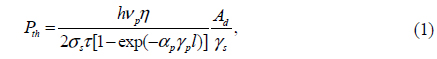
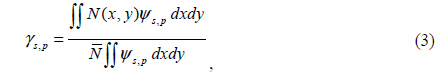
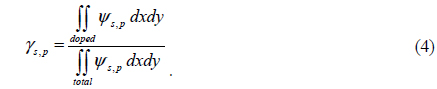
    In general, the lasing threshold Pth of a fiber laser in terms of pump power is given by [21]

    image

    where p is the pump photon energy, σs the emission cross-section of the doped ions at the signal wavelength, τ the active ion’s upper-state fluorescence lifetime, η the round-trip cavity loss, l the length of the gain fiber, and αp the absorption coefficient of the fiber at the pump wavelength, Ad the effective doped area, and γs and γp the OVFs of the signal and pump waves with respect to the doped area, respectively. It is worth noting that Ad is defined by

    image

    where N(x, y) is an arbitrary function for the dopant density distribution in the transverse plane of the fiber. In addition, γs and γp are defined by

    image

    where ψs, p is the modal field intensity at the signal or pump wavelength, and is the mean dopant density for the effective doped area Ad. If we combine Eqs. (2) and (3), assuming that the dopant density function is uniform over the doped region, the OVF can be simplified into

    image

    As a result, the OVF becomes the ratio of the optical power confined in the doped region against the total optical power guided by the fiber.

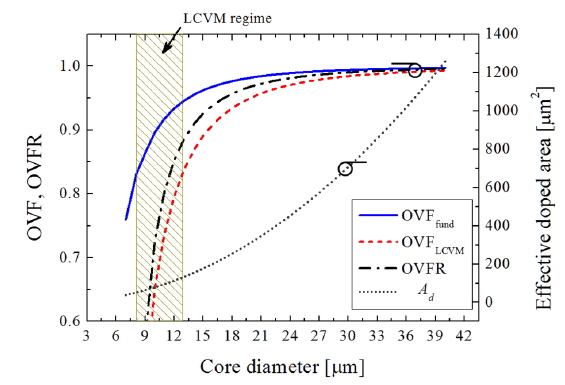
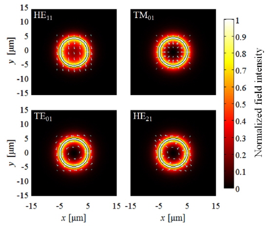
    For standard SICFs, the fundamental mode and the LCVM have clearly different field patterns: The former has a Gaussian-like field distribution whereas the latter has a ring-shaped one having a zero at the center as shown in Fig. 1, where the field intensity distributions of the fundamental mode and the LCVMs (TE01, TM01, and HE21 modes) of a typical SICF having a core diameter of 9.9 μm and a core numerical aperture (NA) of 0.1.

    Thus, one can expect that if a fiber is given in an SICF form and its core is uniformly doped with active ions, the γs of the fundamental mode is invariably higher than that of the LCVM [22]. Consequently, the lasing threshold of the fundamental mode is always lower than that of the LCVM unless any additional mode discrimination mechanism is provided [21, 23] [see Eq. (1)]. In fact, this property can be a severe issue even with an additional mode discrimination measure because the excited ions in the central part of the core have poor overlap with the LCVM signal, so that their energy cannot be extracted efficiently, thereby causing an excessive level of the ASE build-up in the central part of the fiber. Actually, this consequence inevitably results in a significant reduction of the laser conversion efficiency [16-18].

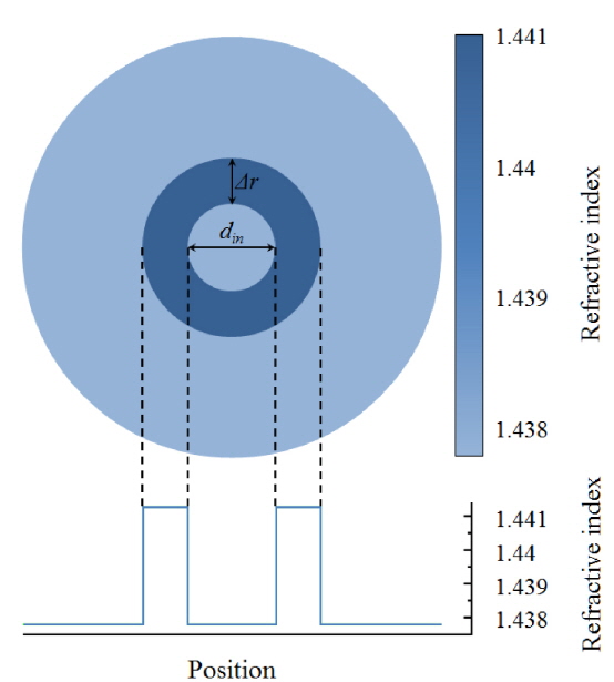
    To overcome such drawbacks of SICFs in generating a CVM, we propose to use an RDCF, introducing a dopant-depleted region at the center of its core. The central dopant-depleted region will prevent the unwanted ASE build-up, and also lead to a good mode overlap between the doped ions and the CVM field.

    III. NUMERICAL RESULTS

       3.1. Limitations of a Step-index Core Fiber (SICF)

    Regarding the fibers under consideration, we utilize a finite-element-method (FEM)-based mode solver (COMSOL Multiphysics®) to obtain the rigorous two-dimensional mode-field distribution. We set the lasing wavelength of interest to be 1.06 μm, assuming that the fiber is doped with Yb ions. In addition, we fix the core NA to be 0.1, which is a typical value for conventional YDFs having an intermediate mode size [24, 25].

    Based on these fiber parameters, we first calculate the OVFs of the SICF modes, varying the core diameter. Then, we calculate the overlap factor ratio (OVFR) of the LCVM with respect to the OVF of the fundamental mode, i.e., γs,LCVM / γs,fund. In fact, this parameter can be an indicative that shows how efficiently the fiber is capable of generating the LCVM. For example, the higher the OVFR is, the higher efficiency the fiber will have in generating the LCVM. In particular, if the OVFR exceeds unity, the lasing threshold of the LCVM will be lower than that of the fundamental mode. In addition, it is worth noting that the LCVMs include TE01, TM01, and HE21 modes, depending of their polarization states, which are all degenerate modes and have nearly identical field intensity patterns under the weakly guiding condition, as shown in Fig. 1. Therefore in terms of the OVF there are no intrinsic differences among them, and one may represent their OVF properties with one representative value hereinafter.

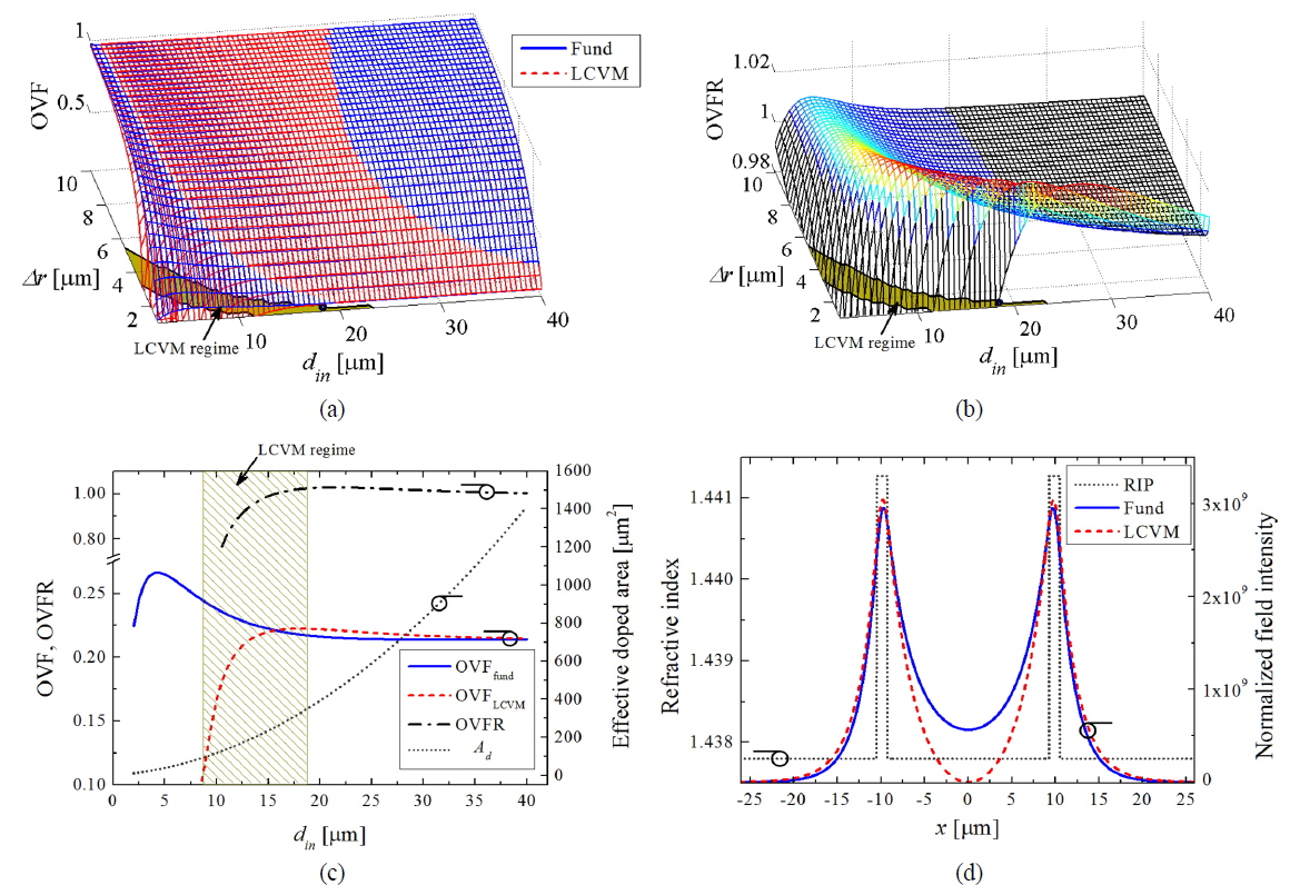
    Figure 2 shows the calculated results for the OVFs of the fundamental mode and the LCVM, the corresponding OVFR between them, and the effective doped area Ad as functions of the core diameter of the SICF. As expected, the results confirm that the OVF of the fundamental mode is invariably higher than that of the LCVM. Consequently, the fundamental mode is the fittest to survive during the mode completion in the laser cavity unless a sufficient special measure is provided to suppress it. In addition, when the core become larger, the OVF of the LCVM tends to converge to that of the fundamental mode. However, this does not mean any improvement for the LCVM generation in terms of the mode selection because as the core size increases, it also becomes a guide for other higher-order modes (HOMs), which in turn reduce the possibility of the LCVM generation [16, 26]. On this account, a desirable operating regime of a fiber is the case when it only supports modes up to the LCVM. The shaded region of Fig. 2 indicates the LCVM regime, when the core diameter is between 8.1 μm and 12.8 μm. The OVFR is maximized to 0.876 at the edge of this region when the core diameter is 12.8 μm. We can observe that the OVFR continuously increases after the LCVM regime. In other words, there is a tradeoff in increasing the OVFR or decreasing the number of modes in the case of a SICF.

       3.2. Design of a Ring-doped-core Fiber (RDCF)

    We now consider an active optical fiber having a core doped with laser-active ions, the refractive-index profile of which has an index well at the center, as depicted in Fig. 3, which is called an RDCF. We propose this structure because it can readily be implemented to a fiber via a modified chemical vapor deposition (MCVD) process [27, 28].

    We assume the NA of the RDCF to be 0.1 as the same of the SICF investigated in the previous section. In fact, this NA will allow the RDCF to guide only the LCVM together with the fundamental mode if the effective mode area is scaled as similarly large as conventional YDFs having an intermediate mode size [24, 25].

    We characterize the OVFs of the fundamental mode and the LCVM, varying din and Δr, where din denotes the inner diameter of the ring-doped core and Δr its thickness in the radial direction, as depicted in Fig. 3. The refractive index profile (RIP) of the RDCF is also shown in Fig. 3. Fig. 4 shows typical field-intensity distributions of the modes guided in an RDCF for din = 18.5 μm and Δr = 1.25 μm. It shows that in the case of the fundamental mode a considerable amount of the field still lies in the central part of the core, i.e., in the index well region where no laser-active ions are doped. In contrast, the field distribution of the LCVM is predominantly bounded within the ring-doped region, so that the field distribution in the index well region is significantly suppressed. Therefore, in this circumstance the OVF of the LCVM can be higher than that of the fundamental mode, and thus, the ASE build-up in the fundamental mode can significantly be reduced.

    Figure 5(a) presents the OVFs of the fundamental mode (blue) and LCVM (red), and Fig. 5(b) presents the corresponding OVFR. In Fig. 5(a), one can see that a specific region exists where the red lines cover up the blue lines. This region represents the range where the OVF of the LCVM is higher than that of the fundamental mode. In particular, this range is highlighted by the color-graded lines in Fig. 5(b), which actually represents the range where the OVFR exceeds unity. The shaded regions on the bottoms of Fig. 5(a) and 5(b) represent the parameter range allowing for operating in the LCVM regime. Figure 5(c) shows the calculated results for the OVFs of the fundamental mode and the LCVM, the corresponding OVFR, and the effective doped area Ad in terms of din, when Δr is fixed to 1.25 μm, for example. The shaded region of Fig. 5(c) also represents the parameter range for the LCVM regime. In contrast to the SICF case (see Fig. 2), one can see that OVFR can exceed unity even in the parameter range for the LCVM regime. This implies that within that specific parameter range the proposed fiber design can facilitate the LCVM operation rather than the fundamental-mode operation.

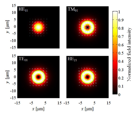
    Figure 5(d) shows the field-intensity distributions of the fundamental mode and the LCVM across the diameter of an RDCF having its parameter set given by din = 18.5 μm and Δr = 1.25 μm. This parameter set is indicated by a circle given in Fig. 5(a) or in Fig. 5(b). In fact, in this condition the OVFR is maximized within the range where the RDCF operates in the LCVM regime, supporting only the fundamental mode and the LCVM, which is eventually given by 1.026. In other words, it indicates the optimized design parameter set for the RDCF, which can lead to a lower lasing threshold for the LCVM than for the fundamental mode. Therefore, if the RDCF is pumped to lase, the LCVM can be the fittest to survive in the mode completion even without relying on any special mode-discrimination measure. Furthermore, in comparison with the case for the SICF, the RDCF yields considerably improved signal overlap with the doped ions even for the LCVM, so that the ASE loss due to the non-overlapped ions will be significantly reduced. This can eventually increase the overall laser efficiency. We emphasize this is the first practical fiber design to introduce higher gain to the LCVM than to the fundamental mode.

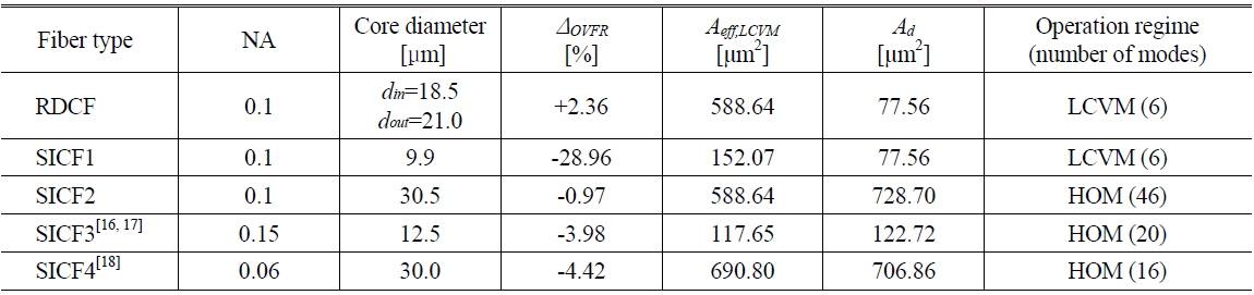
    In addition, we would like to discuss a bit further the OVFR property of the optimized RDCF shown in Fig. 5(d), in comparison with various counterpart SICFs that are conventionally available. This comparison can be indicative of how efficiently the RDCF is capable of generating the LCVM. For various fiber parameter sets, Table 1 summarizes their comparative characteristics, including the NA, the core diameter, the deviation of the OVFR from unity, i.e., ΔOVFR that is given by ΔOVFR = OVFR − 1, the effective mode area of the LCVM Aeff,LCVM, the effective doped area Ad, and the operation regime of the fiber. SICF1 and SICF2 represent the cases having the same effective doped area Ad and the same effective mode area Aeff,LCVM with the RDCF, respectively. SICF3 and SICF4 are the active fibers based on the SICF design demonstrated in Refs. [16, 17] and [18], respectively. In particular, it is worth noting that SICF1 operates in the LCVM regime, which is the same modal operating condition as that of the optimized RDCF. In this respect, the ΔOVFR value of SICF1 can be an imperative factor for making a fair comparison with the optimized RDCF. We highlight that the optimized RDCF offers a substantially higher ΔOVFR value than that of SICF1, allowing for an improvement of over 30 %. Another advantage offered by the optimized RDCF is that its effective mode area for the LCVM, i.e., Aeff,LCVM, is substantially larger than that of SICF1, which is an extremely important factor for mitigating the undesirable nonlinear effects in the fiber, such as stimulated Raman scattering, stimulated Brillouin scattering, optical Kerr effect, etc. [24, 29-31]. While SICF2, SICF3, and SICF4 show better performance than SICF1 in terms of OVFR, one cannot expect the overall performance for generating the LCVM out of them will be in the same manner because they predominantly operate in HOM regimes. In other words, the mode competition among the LCVM and the HOMs will substantially exacerbate the overall laser performance and efficiency even if the LCVM lasing is possible by any chance.

    [TABLE 1.] The characteristic parameters of the optimized RDCF and various SICFs

    label

    The characteristic parameters of the optimized RDCF and various SICFs

    IV. CONCLUSION

    We have proposed and designed a novel RDCF that can efficiently support the LCVM generation in an all-fiber format. Through rigorous numerical analyses of RDCFs, we found that unlike SICFs, RDCFs can make the OVF of the LCVM exceed that of the fundamental mode. For an optimized RDCF that has the effective mode area of the LCVM (Aeff,LCVM) of 588. 64 μm2 and the effective doped area (Ad) of 77.56 μm2, its OVFR is eventually given by 1.023, which can lead to single LCVM operation when it is pumped to lase. This OVFR value is over 30% higher than that of a SICF having the same doped area as the RDCF. We stress this is the first practical active fiber design that can introduce higher gain to the LCVM than to the fundamental mode. In fact, the proposed fiber design can prevent undesirable mode conversions to the fundamental mode or any higher-order modes, thereby being capable of suppressing the unwanted ASE loss owing to them. We expect this numerical study will be beneficial to the future research in designing or fabricating active fibers aimed for the generation of CVBs.

참고문헌
  • 1. Zhan Q 2009 “Cylindrical vector beams: From mathematical concepts to applications,” [Adv. Opt. Photon.] Vol.1 P.1-57 google cross ref
  • 2. Zhan Q 2004 “Trapping metallic Rayleigh particles with radial polarization,” [Opt. Express] Vol.12 P.3377-3382 google cross ref
  • 3. Biss D. P., Brown T. G. 2003 “Polarization-vortex-driven second-harmonic generation,” [Opt. Lett.] Vol.28 P.923-925 google cross ref
  • 4. Bautista G., Huttunen M. J., Makitalo J., Kontio J. M., Simonen J., Kauranen M. 2012 “Second-harmonic generation imaging of metal nano-objects with cylindrical vector beams,” [Nano Lett.] Vol.12 P.3207-3212 google cross ref
  • 5. Zhan Q. 2006 “Evanescent Bessel beam generation via surface plasmon resonance excitation by a radially polarized beam,” [Opt. Lett.] Vol.31 P.1726-1728 google cross ref
  • 6. Zhan Q., Leger J. R. 2002 “Focus shaping using cylindrical vector beams,” [Opt. Express] Vol.10 P.324-331 google cross ref
  • 7. Kozawa Y., Sato S. 2005 “Generation of a radially polarized laser beam by use of a conical Brewster prism,” [Opt. Lett.] Vol.30 P.3063-3065 google cross ref
  • 8. Phua P. B., Lai W. J. 2007 “Simple coherent polarization manipulation scheme for generating high power radially polarized beam,” [Opt. Express] Vol.15 P.14251-14256 google cross ref
  • 9. Quabis S., Dorn R., Leuchs G. 2005 “Generation of a radially polarized doughnut mode of high quality,” [Appl. Phys. B] Vol.81 P.597-600 google cross ref
  • 10. Nesterov A. V., Niziev V. G., Yakunin V. P. 1999 “Generation of high-power radially polarized beam,” [J. Phys. D: Appl. Phys.] Vol.32 P.2871-2875 google cross ref
  • 11. Euser T. G., Schmidt M. A., Joly N. Y., Gabriel C., Marquardt C., Zang L. Y., Fortsch M., Banzer P., Brenn A., Elser D., Scharrer M., Leuchs G., Russell P. St. J. 2011 “Birefringence and dispersion of cylindrically polarized modes in nanobore photonic crystal fiber,” [J. Opt. Soc. Am. B] Vol.28 P.193-198 google cross ref
  • 12. Tidwell S. C., Ford D. H., Kimura W. D. 1990 “Generating radially polarized beams interferometrically,” [Appl. Opt.] Vol.29 P.2234-2239 google cross ref
  • 13. Rawson E. 1973 U.S. Patent google
  • 14. Ramachandran S., Kristensen P., Yan M. F. 2009 “Generation and propagation of radially polarized beams in optical fibers,” [Opt. Lett.] Vol.34 P.2525-2527 google cross ref
  • 15. Uebel P., Schmidt M. A., Scharrer M., Russell P. S. J. 2011 “An azimuthally polarizing photonic crystal fibre with a central gold nanowire,” [New J. Phys.] Vol.13 P.063016 google cross ref
  • 16. Li J.-L., Ueda K.-I., Shirakawa A., Musha M., Zhong L.-X., Zhang Z.-M. 2007 “39-mW annular excitation of ytterbium fiber laser with radial polarization,” [Laser Phys. Lett.] Vol.4 P.814-818 google cross ref
  • 17. Li J.-L, Ueda K.-I., Musha M., Shirakawa A., Zhang Z.-M. 2007 “Converging-axicon-based radially polarized ytterbium fiber laser and evidence on the mode profile inside the gain fiber,” [Opt. Lett.] Vol.32 P.1360-1362 google cross ref
  • 18. Kanazawa S., Kozawa Y., Sato S. 2014 “High-power and highly efficient amplification of a radially polarized beam using an Yb-doped double-clad fiber,” [Opt. Lett.] Vol.39 P.2857-2859 google cross ref
  • 19. Jeong Y., Boyland A. J., Sahu J. K., Chung S., Nilsson J., Payne D. N. 2009 “Multi-kilowatt single-mode ytterbium-doped large-core fiber laser,” [J. Opt. Soc. Korea] Vol.13 P.416-422 google cross ref
  • 20. Desurvire E. 1994 Erbium-Doped Fiber Amplifiers Principles and Applications google
  • 21. Digonnet M. J. F., Gaeta C. J. 1985 “Theoretical analysis of optical fiber laser amplifiers and oscillators,” [Appl. Opt.] Vol.24 P.333-342 google cross ref
  • 22. Selvas R., Sahu J. K., Fu L. B., Jang J. N., Nilsson J., Grudinin A. B., Yla-Jarkko K. H., Alam S. A., Turner P. W., Moore J. 2003 “High-power, low-noise, Yb-doped, cladding-pumped, three-level fiber sources at 980 nm,” [Opt. Lett.] Vol.28 P.1093-1095 google cross ref
  • 23. Okamoto K. 2006 Chapter 3 google
  • 24. Jeong Y., Sahu J. K., Payne D. N., Nilsson J. 2004 “Ytterbium-doped large-core fiber laser with 1.36 kW continuous-wave output power,” [Opt. Express] Vol.12 P.6088-6092 google cross ref
  • 25. Rousseau J.-C., Sauvageon R. 2000 U.S. Patent google
  • 26. Lee S., Vazquez-Zuniga L. A., Lee D., Kim H., Sahu J. K., Jeong Y. 2013 “Comparative experimental analysis of thermal characteristics of ytterbium-doped phosphosilicate and aluminosilicate fibers,” [J. Opt. Soc. Korea] Vol.17 P.182-187 google cross ref
  • 27. Gambling W. A., Payne D. N., Matsumura H. 1975 “Mode conversion coefficients in optical fibers,” [Appl. Opt.] Vol.14 P.1538-1542 google cross ref
  • 28. Townsend J. E., Poole S. B., Payne D. N. 1987 “Solution doping technique for fabrication of rare-earth doped optical fibers,” [Electron. Lett.] Vol.23 P.329-331 google cross ref
  • 29. Dupriez P., Piper A., Malinowski A., Sahu J. K., Ibsen M., Thomsen B. C., Jeong Y., Hickey L. M. B., Zervas M. N., Nilsson J., Richardson D. J. 2006 “High average power high repetition rate picosecond pulsed fiber master oscillator power amplifier source seeded by a gain-switched laser diode at 1060 nm,” [IEEE Photon. Technol. Lett.] Vol.18 P.1013-1014 google cross ref
  • 30. Richardson D. J., Nilsson J., Clarkson W. A. 2010 “High power fiber lasers: Current status and future perspectives,” [J. Opt. Soc. Am. B] Vol.27 P.B63-B92 google cross ref
  • 31. Park K., Jeong Y. 2014 “A quasi-mode interpretation of acoustic radiation modes for analyzing Brillouin gain spectra of acoustically antiguiding optical fibers,” [Opt. Express] Vol.22 P.7932-7946 google cross ref
OAK XML 통계
이미지 / 테이블
  • [ ] 
  • [ ] 
  • [ ] 
  • [ ] 
  • [ FIG. 1. ]  The field intensity distributions of (a) the fundamental mode and (b)-(d) the LCVMs of a typical SICF when the core diameter is 9.9 μm. The arrowed lines denote the directions of the electric field vectors.
    The field intensity distributions of (a) the fundamental mode and (b)-(d) the LCVMs of a typical SICF when the core diameter is 9.9 μm. The arrowed lines denote the directions of the electric field vectors.
  • [ FIG. 2. ]  The OVF for each mode, the corresponding OVFR, and the effective doped area (Ad) of the SICF regarding to the diameter.
    The OVF for each mode, the corresponding OVFR, and the effective doped area (Ad) of the SICF regarding to the diameter.
  • [ FIG. 3. ]  The structure of the proposed RDCF.
    The structure of the proposed RDCF.
  • [ FIG. 4. ]  The field intensity distributions of (a) the fundamental mode and (b)-(d) the LCVMs of the RDCF when din =18.5 μm and Δr =1.25 μm. The arrowed lines denote the directions of the electric field vectors.
    The field intensity distributions of (a) the fundamental mode and (b)-(d) the LCVMs of the RDCF when din =18.5 μm and Δr =1.25 μm. The arrowed lines denote the directions of the electric field vectors.
  • [ FIG. 5. ]  (a) and (b): The OVF and the OVFR of the RDCF, respectively. (c) The OVF for each mode, the corresponding OVFR, and the effective doped area (Ad) of the RDCF with respect to din when Δr is fixed to 1.25 μm. (d) The field intensity distributions of the fundamental mode and the LCVM, together with the RIP of the RDCF when din =18.5 μm and Δr =1.25 μm.
    (a) and (b): The OVF and the OVFR of the RDCF, respectively. (c) The OVF for each mode, the corresponding OVFR, and the effective doped area (Ad) of the RDCF with respect to din when Δr is fixed to 1.25 μm. (d) The field intensity distributions of the fundamental mode and the LCVM, together with the RIP of the RDCF when din =18.5 μm and Δr =1.25 μm.
  • [ TABLE 1. ]  The characteristic parameters of the optimized RDCF and various SICFs
    The characteristic parameters of the optimized RDCF and various SICFs
(우)06579 서울시 서초구 반포대로 201(반포동)
Tel. 02-537-6389 | Fax. 02-590-0571 | 문의 : oak2014@korea.kr
Copyright(c) National Library of Korea. All rights reserved.