The demand for multimedia communication service is increasing beyond expectation, as video services through smart phones and wired subscriber networks are exploding. The increase of communication traffic in the end-user network requires wideband and smart fiber-optic backbone networks. In the backbone networks of the future, the packets will need to be all-optically routed, without the intervention of conversion between optical and electrical signals [1]. To realize all-optical routing networks, variable delay components are required for the buffering process. Ring resonator all-pass filters (APFs) are good candidates for variable optical delay devices [2-5]. Even though several approaches in analytical and numerical analysis provide lots of information regarding the delay performance of ring resonator devices [5], the quality of delayed pulse shapes can be directly investigated through a time-domain analysis.
Recently, a split-step large-signal time-domain modeling approach was reported, offering direct and easy analysis of pulse response of ring resonator delay devices [6]. In this paper, single-ring APFs with various coupling ratios, two-ring APFs, and three-ring APFs are designed, fabricated, and characterized to evaluate the effectiveness of the split-step time-domain modeling. The measurement results are shown to agree fairly well with the time-domain modeling results, in terms of delay time and qualitive pulse shape, which confirms the usefulness of the split-step time-domain modeling approach. Split-step time-domain modeling can be efficiently incorporated into an advanced optical communication modeling tool, when the ring resonator delay devices are present in optical packet switching systems.
II. SPLIT-STEP TIME-DOMAIN MODEL
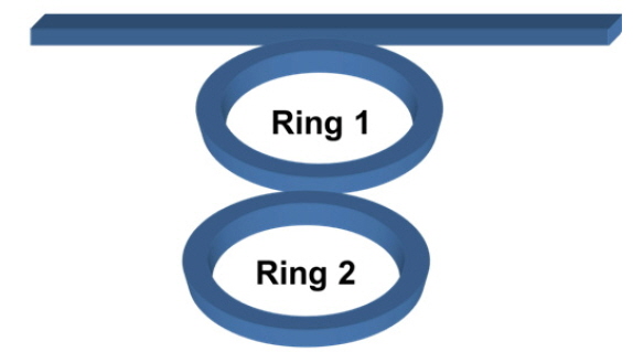
A two-ring resonator APF, shown in Fig. 1, is considered to illustrate the split-step time-domain model (SS-TDM) employed in this paper. In this model, the numerical solution of the time-dependent coupled-wave equation is found through a split-step operator approach. The SS-TDM consists of the numerical solution of the time-dependent coupled-wave equations for forward and reverse waves [6, 7].
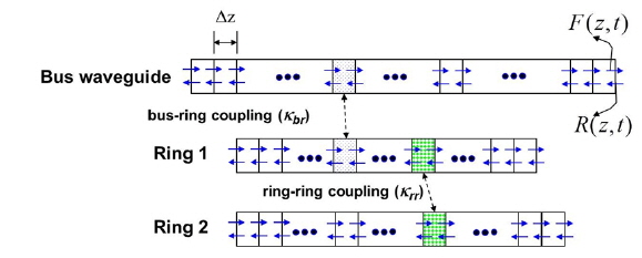
The time-dependent coupled-wave equations can be numerically solved by dividing the bus and ring waveguides into a number of small subsections of equal length
First, the forward/reverse waves in three waveguides (a bus and two ring waveguides) are updated to incorporate the attenuation and phase accumulation through a section in a time step. Then, the coupling effects between waveguides are taken into consideration. The appropriate boundary conditions in the bus and ring waveguides are applied at every time step. This approach can be extended as the number of coupled rings increases.
III. EXPERIMENTAL AND SIMULATION RESULTS FOR RING RESONATOR ALL-PASS FILTERS
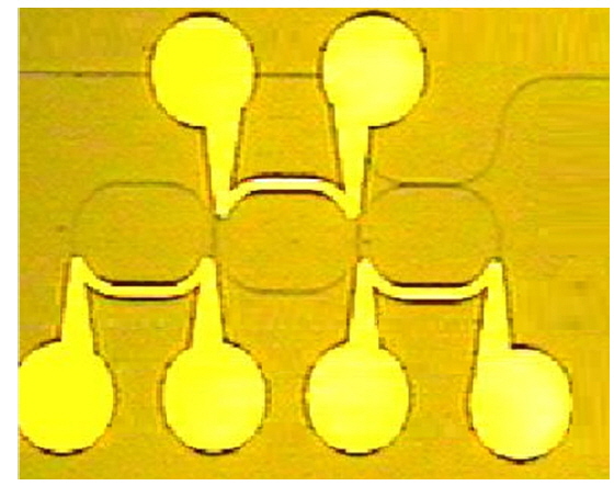
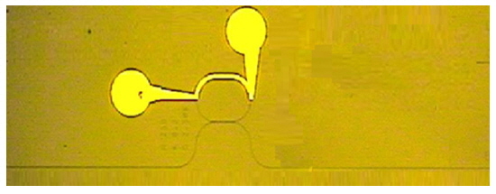
The top view of a fabricated single-ring resonator APF is shown in Fig. 3. The waveguide core is filled with ZPU-12 polymer (product of ChemOptics Co.), with equal width and height of 1.8 μm. LFR polymer (product of ChemOptics Co.) cladding material surrounds the core. The refractive indices of core and cladding near the wavelength of 1.55 μm are 1.48 and 1.37 respectively, which corresponds to a relative index difference of 7.4%. The dispersion of ZPU-12 is −4.6×10⁻⁶ nm−1, according to data from ChemOptics Co. The high index contrast between core and cladding results in strong optical confinement in the waveguide, so the ring resonator device can be made very compact by minimizing bending loss for quite a small ring radius [3]. Electrodes are evaporated on top of the ring resonators for thermal tuning of the resonance wavelength. The effective and group refractive indices of the straight polymer waveguide are 1.426504 and 1.435055 respectively. The radius of the curved waveguide in the rat-race track ring is 250 µm, which is large enough to provide neglible bending loss. In other words, the curved waveguide mode is well confined inside the core region, and the effective and group indices of the curved waveguide are found to be almost the same as those of the straight waveguide. Therefore, the same refractive index values are used both for the straight and curved waveguides in the following simulations. Including the straight waveguide length in the coupling region, the free spectral range is designed to be about 100 GHz, which corresponds to a round-trip time of about 10 ps around the ring.
The shape of the ring resonator is a rat-race track composed of two semicircles of radius 250 µm plus two straight waveguides of length 213 µm. To investigate the effect of coupling ratio on the time delay characteristics, we designed and fabricated single-ring APFs with different coupling ratios. The target coupling ratios of the bus-ring couplers in the single-ring APFs are 0.4, 0.5, 0.6, and 0.8 respectively. The various coupling ratios are achieved by adjusting the gap between the bus and the straight waveguides in the rat-race track. The gaps are designed to be 2.07 µm, 1.93 µm, 1.8 µm, and 1.58 µm respectively, to achieve the four coupling ratios. The fabrication process is as follows: The cladding material (LFR) is spin-coated on a silicon wafer and baked for 30 minutes at a temperature of 200℃. The waveguide core regions are removed from the cladding polymer using photolithography and a dry-etching process. The core polymer material (ZPU-12) is filled by spin-coating and hardened through UV irradiation and thermal curing, and then the polymer on top of the core region is removed using a plain dry-etching process. Finally the 5.1-μm-thick cladding polymer is spin-coated, baked, and cured to form the upper cladding [8].
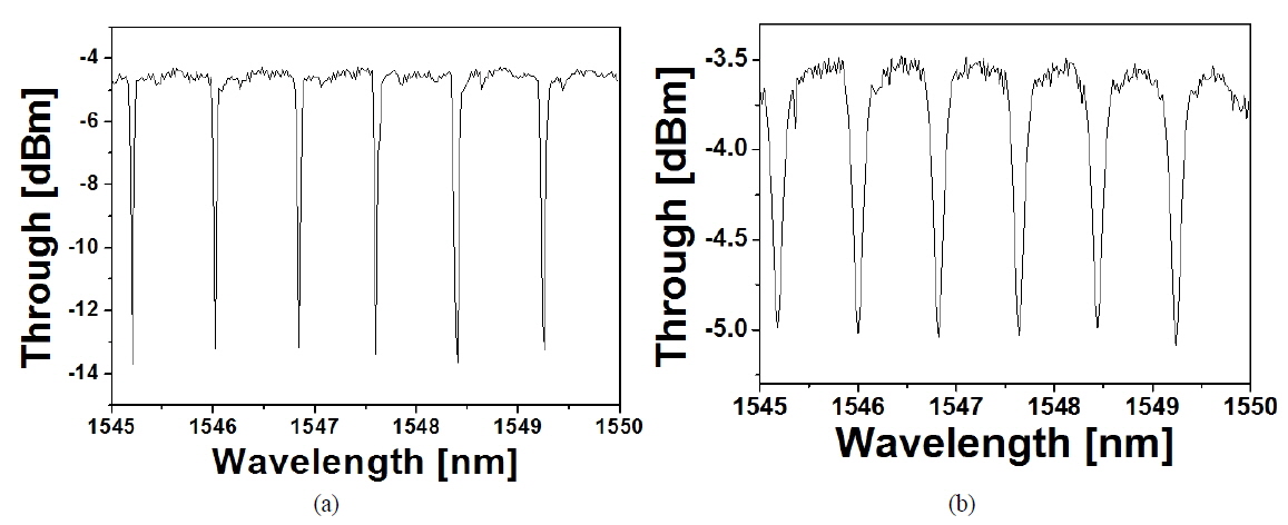
The pass-through characteristics as a function of wavelength are measured and shown in Fig. 4 for coupling ratios of 0.4 and 0.8. The free spectral range is measured to be 0.82 nm, which corresponds to the fabricated ring resonator geometry. The setup for the pulse delay measurement is as follows: The optical waves from the tunable laser are modulated by a LiNbO3 modulator, to which an electrical pulse signal from a pulse pattern generator is applied. A TE-polarized pulse signal is launched into a singlering APF through a polarization controller. The FWHM (full width at half maximum) pulse width is about 230 ps. The optical pulse signal through the APF is amplified by an EDFA (Erbium-Doped Fiber Amplifier), and the time delay characteristics are measured using a DCA (Data Communication Analyzer), which can display the optical signal waveform directly with its built-in detector of bandwidth 20 GHz.
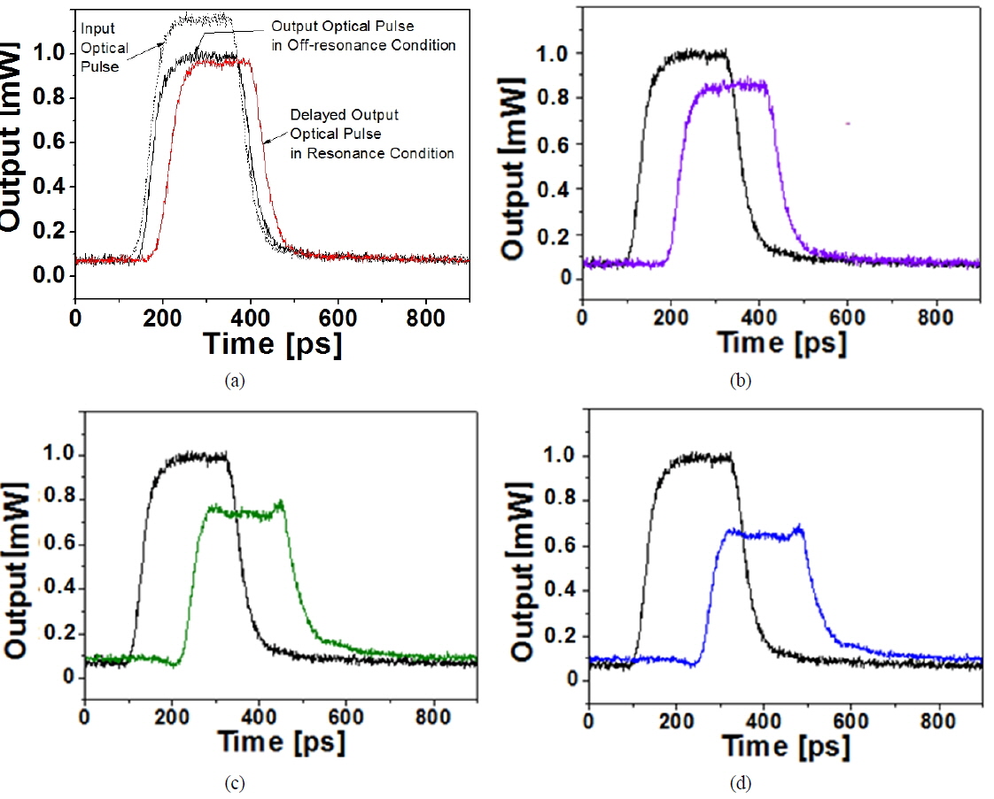
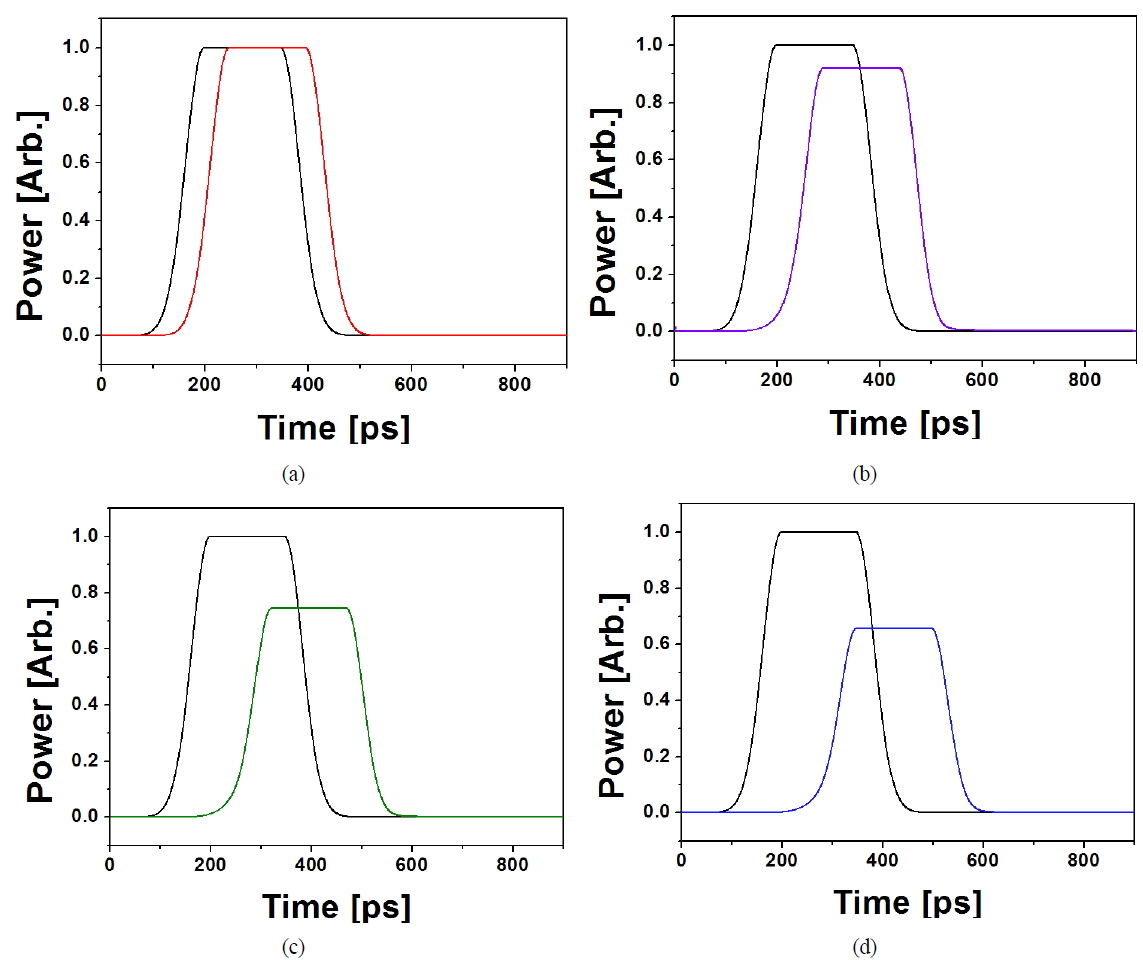
The delay measurement results for the APFs are shown in Fig. 5. During the measurement the wavelength is set to 1546.14 nm, at which the ring is nonresonant without current injection. The tuning current is applied to make the ring resonant, and the delay is observed. When the coupling ratio of the single-ring APFs is 0.4, 0.5, 0.6, and 0.8, the delay times are measured to be about 145, 115, 86, and 42 ps respectively. In Fig. 5(a) the input optical pulse, as well as the output pulses in the nonresonant and resonant conditions, are displayed for comparison. The shape of the nonresonant output pulse is essentially the same as that of the input pulse. In the figure, the timing of the input pulse is shifted for comparison. Figure 6 shows the split-step time-domain modeling results of the APFs having various coupling ratios. In the calculation, the propagation loss of the waveguide is assumed to be 1.5 dB/cm. The simulation time for a single-ring APF is about 3 seconds when the subsection length
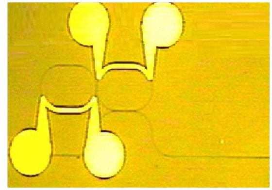
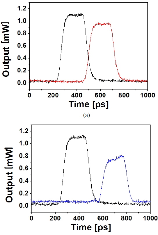
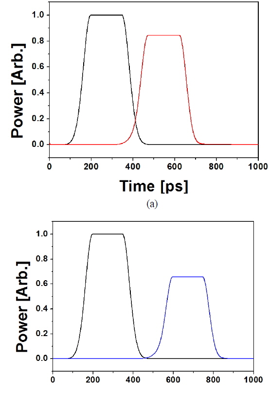
The APFs with two coupled rings and three coupled rings are also fabricated, to compare the delay measurement results with simulation results. The coupling ratio between the bus and ring waveguide is designed to be 0.5, for which the gap in the mask pattern is 1.93 µm. The coupling ratio between the rings in the two-ring APF is designed to be 0.12, for which the gap in the mask pattern is 1.46 µm. In the three-ring APF (Fig. 8), the coupling ratio between the leftmost and the center rings is designed to be 0.12, and that between the center and rightmost rings 0.08, for which the gap is designed to be 1.73 µm. The geometry of the ring resonators is the same as that of the single-ring APF discussed in the above. Photographs of the fabricated two- and three-ring APFs are shown in Figs. 7 and 8 respectively; the measured delay characteristics are shown in Fig. 9. The delay times through the two- and three-ring APFs are observed to be 238 and 330 ps respectively. The split-step time-domain simulation results of the pulse delay characteristics through the two- and three-ring APF are also shown in Fig. 10, and the delay times are observed to be 276 and 397 ps respectively, which corresponds reasonably well to the experemental results. Some discrepancy between experiment and simulation could be due to actual coupling ratios being slightly different from the nominal design values.
We designed and fabricated polymer single-ring APFs with various coupling ratios, as well as two- and three-ring APFs, to evaluate the split-step time-domain modeling approach, which is considered a beneficial tool to assess the pass-through characteristics of an optical pulse signal through the APFs.
The time delay is measured by tuning the resonance wavelength of the ring near the operating wavelength. When the coupling ratio of the single-ring APF is 0.4, 0.5, 0.6, and 0.8, the delay is measured to be about 145, 115, 86, and 42 ps respectively. The measured delay times are quite comparable to the time-domain modeling results, which are 151, 123, 92, and 47 ps respectively. The delay times of the two- and three-ring APFs are measured to be 238 and 330 ps, which are quite close to the simulation results of 276 and 397 ps respectively. The shape of the delayed pulses in the experiment also agrees well with that from simulation, confirming the accuracy of the split-step time-domain modeling. The simulation time for a single-ring APF is as short as about 3 seconds, which illustrates the efficiency of the model. From these experiments and simulations, the split-step time-domain model exhibits the potential to be efficiently incorporated into a simulation tool for optical communcation, for the case of ring resonator delay devices in all-optical packet switching systems.