It has been demonstrated that integral imaging is an autostereoscopic technique that shows a full-color, full-parallax, real three-dimensional (3D) image [1]. Also, real-time 3D pictures can be provided with relatively low eye fatigue by an integral imaging display. However, integral imaging systems have many challenges, such as a narrow viewing angle, the spatial limitation of resolution, and the expressible depth range. It has been reported that these parameters exhibit a trade-off relationship [2]. Since the first proposal by Lippmann, integral imaging systems have been further developed and improved by many research groups [3-5].
A projector can be used as the display device for the elemental images in an integral imaging system, which is called projection-type integral imaging. Employing a diffuser screen in the elemental image plane, the projection-type integral imaging system uses the same method as an ordinary integral imaging system [6-11], but, due to the diffuser, the resolution and brightness of the elemental image are restricted in projection-type integral imaging. To overcome these weaknesses, previous studies have proposed some kinds of projection-type systems without the diffuser and reported a method for evaluating the visibility of the reconstructed images in terms of the fill factor [12]. This system has the strength that spatial and/or temporal multiplexing is feasible. Also, multiple elemental image layers can be used within the depth of field of the projector [13, 14].
In this paper, we apply a pico-projector to projection-type integral imaging, without a diffuser, in real-display mode. Due to the infinite focus of the pico-projector, the location of central depth plane (CDP) can be controlled in a projection-type integral imaging system. Using matrix analysis, ray tracing is performed at the CDP, and the compensation of elemental images for this system is proposed. Some experiments and their results are presented to prove the feasibility of the proposed method.
II. PROJECTION-TYPE INTEGRAL IMAGING SYSTEM USING A PICO-PROJECTOR
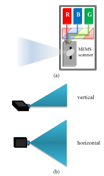
The pico-projector is a compact and mobile projector that has an infinite focus. As this technology is expected to be embedded in other devices such as smart phones and digital cameras, pico-projectors are drawing much attention. According to its operating method, a pico-projector is categorized according to three types: digital light processing (DLP), liquid crystal on silicon (LCoS), or laser beam steering (LBS). Figure 1 (a) shows the basic layout of a LBS-type picoprojector [15]. As shown, there is no projection lens set. The projected beam with low numerical aperture (NA) leaves the pico-projector directly and creates an image that is always in focus. The projected image grows as its distance from the pico-projector increases, as shown in Fig. 1(b).
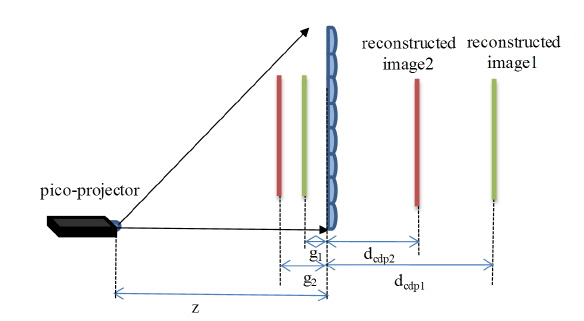
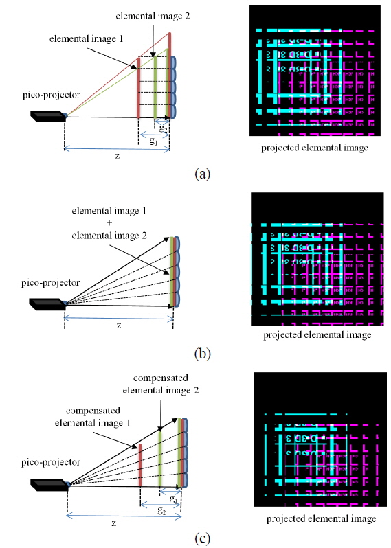
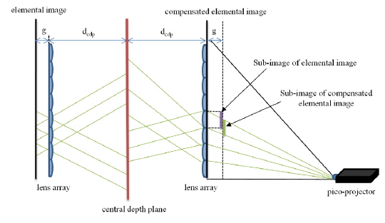
In an integral imaging system, the reconstructed image can be formed near the CDP. The location of the CDP depends on the gap between the lens array and the elemental image, according to the Gauss lens law. In a projectiontype integral imaging system without a diffuser, multiple elemental images can be projected within the depth of field, which generates multiple central depth planes [16]. Because the depth of field of a pico-projector is almost infinite, the region of expressible CDP can be expanded by using multiple elemental image planes. As shown in Fig. 2, elemental images with different gaps can be projected and integrated into reconstructed images with different CDPs. This means that the location of the CDP can be controlled solely by image processing, without changing the distance between projector and lens array. In this paper, we divide projection-type integral imaging systems into two cases, to analyze and propose the processing for the compensated elemental images.
First, as in a conventional integral imaging system, the elemental image is aligned with the gap

where
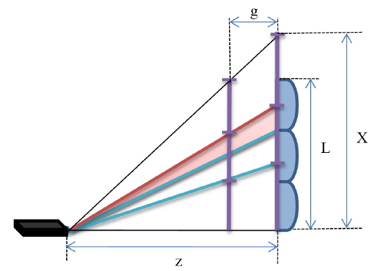
Because the size of the elemental image at the lens array is bigger than the lens array, some rays passing through neighboring lenses lead to image flipping. As the gap becomes bigger and the distance
To solve the image flipping problem in a projection-type integral imaging system, the size of the elemental image can be matched to that of the elemental lens at the location of the lens array, where the gap is zero in Eq. (1). In this case image flipping does not occur, but the size and location of the reconstructed image are deformed from their intended values, due to gap variation. Therefore, elemental image compensation seems necessary to render the integrated image without distortion or image flipping.
In this paper, we analyze the image transfer matrix for a projection-type integral imaging system, and propose an elemental image compensation method to resolve the deformation of the reconstructed image, to present the intended size and depth of the integrated image without the image flipping problem.
III. MATRIX ANALYSIS AND PROPOSED SYSTEM
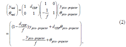
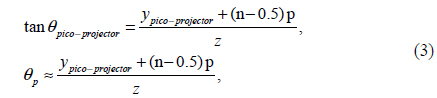
The compensation of the elemental image for the pico-projector is implemented using pixel mapping. Because each pixel has an angle correspondeding to the pixel emitted from the pico-projector, ray tracing at the CDP becomes effective and simple with the matrix method. The elemental image projected at the lens array passes the lens array and travels to the CDP, which is expressed by

where
The angle


where
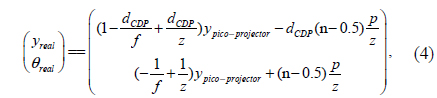
A conventional integral imaging system is described by
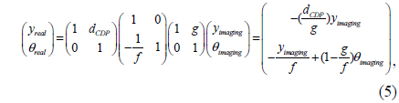
where
The elemental image of a projection-type integral imaging system must be compensated to represent the integrated image at the intended location with the exact intended size. This compensation can be performed to match the corresponding terms of Eq. (4) with Eq. (5), which means
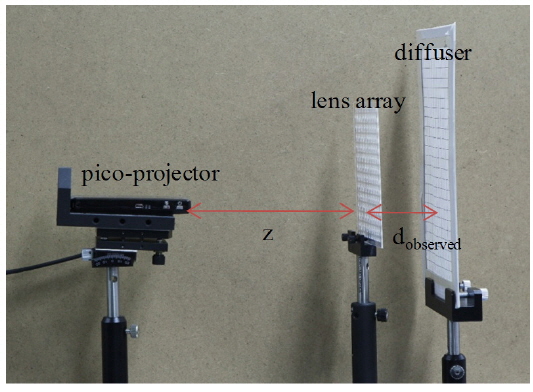
Figure 5 shows a schematic diagram of the experimental setup. We use the SHOWX+TM laser pico-projector with WVGA resolution (848 × 480). In the experiment, we set the distance
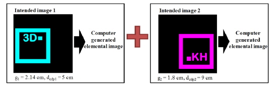
Like the system shown in Fig. 2, two elemental images with different gaps are used to confirm the expansion of the expressible depth. Also, the sizes and locations of the reconstructed images must be adjusted to be like the designed reconstructed images. As shown in Fig. 6, images 1 and 2 are intended to represent the reconstructed image. The size of each square in images 1 and 2 is the same. Two elemental images are generated from image 1 with a gap of 2.14 cm, and from image 2 with a gap of 1.8 cm. Comparing the experimental results for three cases, the reconstructed images are observed using a diffuser and measured at the distance
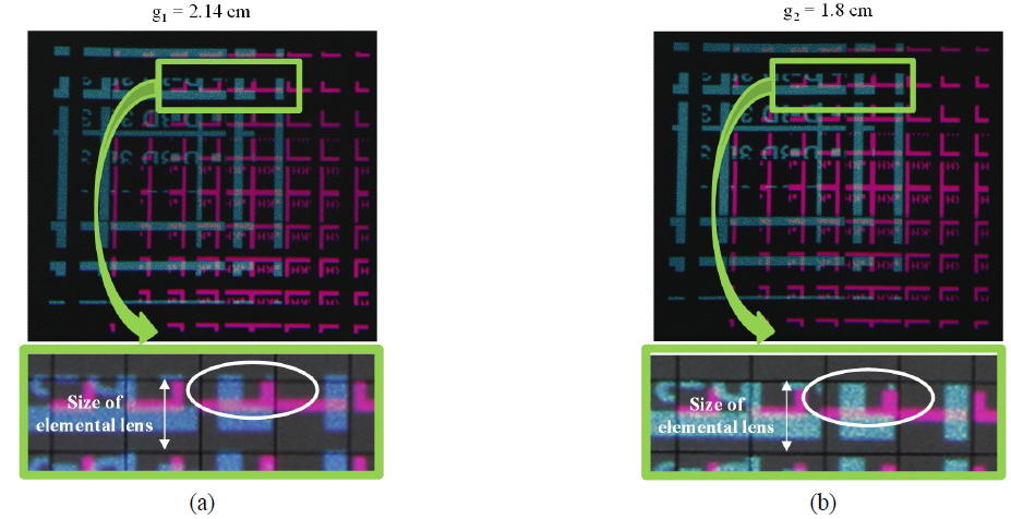
Figure 8 shows the elemental images on the diffuser located at the different gaps, 2.14 cm and 1.8 cm, generated for case 1 of Fig. 7. The elemental image without compensation is used to check the changes of the elemental image planes. In this experiment, two elemental image planes are implemented. Figure 8(a) shows the elemental image when the diffuser is set 2.14 cm from the lens array, while in Figure 8(b) it is located at 1.8 cm. Comparison of the period of the elemental image and the size of elemental lens show that the elemental image plane for the red image is located at gap 1, while the elemental image plane for the blue image is set at gap 2. The integrated images obtained from these elemental images prove this assumption, as shown in Fig. 9, as they are located at the intended position calculated using the lens equation.
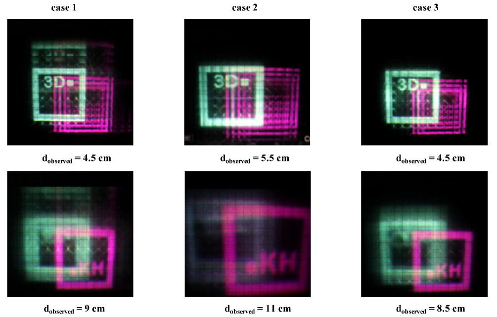
Figure 9 shows the experimental results. The first column in Fig. 9 shows the results for case 1, while the second and third columns show the results for cases 2 and 3. The reconstructed images for images 1 and 2 are located at each
As expected, case 1 presents the image flipping problem, and in case 2 the reconstructed images of elemental images 1 and 2 are located at 5.5 cm and 11 cm respectively, which are not the same as the designed depth. Especially, the reconstructed image of elemental image 2 in the second row shows a problem in terms of its size. Meanwhile, case 3 shows the intended size and depth, without image flipping.
In this paper, we apply a pico-projector to a projection-type integral imaging system to expand the CDP. We propose an elemental image compensation method using matrix analysis and an image mapping algorithm. The results of basic experiments show that the proposed system has multiple CDPs without the image flipping problem, unlike a conventional system.
The image flipping problem occurs in a projection-type integral imaging system due to the divergence property of the projector. In this paper, the compensation is performed assuming low numerical aperture light from the pico-projector. However, the proposed method could also be applied directly to a system adopting a conventional projector, considering the working distance of the chosen projector. So to speak, the proposed compensation method can be used to represent the intended integrated image without a flipped image for a projection-type integral imaging system in general. Experiments are performed to verify the reconstructed image without the image flipping problem. In this paper, reconstructed images with two different depths are investigated using a diffuser. Plane images are used for convenience in the experiments, yet not only separated plane images but also a continuous-volume image can be represented using the proposed system. However, the visibility of the integrated image might be degraded, so as to be unobservable by the naked eye, because of the small aperture of the projection system. This low visibility is caused by the aperture limitation of the projection system and generally occurs in a projection-type integral imaging system without a diffuser, as reported in previous studies [12]. The main proposal and contribution of this paper concern elemental image compensation to resolve image flipping and deformation, not visibility improvement. The reconstructed image on a diffuser located at the CDP can verify the proposed method to modify the size and location of the integrated images, without image flipping. Visibility enhancement could be achieved by adopting special viewing aids like a 3D screen, which is an optical device to resolve the aperture limitation due to the projection lens set by keeping the parallaxes of a 3D image, and can be a proper solution to improve the visibility of projection-type integral imaging [17-19]. Further studies are needed to apply a 3D screen to the proposed system effectively, which could increase the practical utility of the projection-type integral imaging system.