검색 전체 메뉴
PDF
맨 위로
OA 학술지
Holographic Reconstruction of Finite Airy Beams with Self-Healed and Multiplexed Features
  • 비영리 CC BY-NC
  • 비영리 CC BY-NC
ABSTRACT
Holographic Reconstruction of Finite Airy Beams with Self-Healed and Multiplexed Features
KEYWORD
Finite Airy beam , Holography , Angular multiplexing
  • I. INTRODUCTION

    An Airy beam is a nonspreading wave that propagates along a ballistic trajectory without any external force. Since Berry and Balazs illuminated this strange characteristic of the Airy wave packet in quantum mechanics [1], interest in Airy beams has steadily increased [2-18].

    Although it is impossible to implement ideal Airy beams because they carry infinite power, so-called finite Airy beams can be achieved by tailoring infinite side lobes with an aperture function; these finite beams have propagation characteristics similar to those of ideal Airy beams, as was first shown by Siviloglou and Christodoulides [2]. Based on their report, the first optical observation of Airy beams was realized by an optical Fourier-transform system that imposed cubic phase on a broad Gaussian beam [3]. According to the same principle, nonlinear generation of Airy beams [4], curved plasma channel generation [5], and electron-beam generation [6] were reported. Another way to generate a finite Airy beam, which directly assigns the initial launching conditions, was also suggested [7]. By matching initial intensity and phase distributions of Airy beams with those of surface plasmon polaritons (SPPs) after passing through metal slits or gratings, (1+1)-dimensional ((1+1)D) Airy beams can be launched. Also, an Airy beam generated in free space can be coupled via periodic gratings on a metal surface and dynamically controlled by changing the position of either the objective lens or phase mask [8].

    In this paper, we propose holographic generation of finite Airy beams by “reading” a hologram that is recorded as the interference between a finite Airy beam, generated by optical Fourier transform, and a reference plane wave [9]. Although bulk optical components are necessary in the initial recording process, once the initial recording is over we can generate finite Airy beams using only a simple plane wave. Moreover, this method can exploit the unique features of holography itself, such as successful reconstruction even with imperfect incidence of the reference beam, and multiplexing of several Airy beams.

    This paper is organized as follows. After a brief introduction to Airy beams in Section II, in Section III we show that the holographically generated beam maintains non-diffracting nature with a bending trajectory, as well as self-healing. Finally, in Section IV, using the characteristics of holography, we present angular multiplexing of two Airy beams determined by the angles of reference beams.

    II. THEORETICAL ANALYSIS OF AIRY BEAMS

    Let us invoke the solution of a (1+1)D Airy beam from the paraxial Helmholtz equation with the potential-free condition:
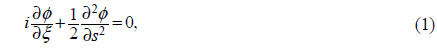
    image

    where ϕ denotes the optical field, and s (=x/x0, with x0 being an arbitrary scaling factor) and ξ (=z/kx02, k being the wavenumber in a propagating medium) represent the transverse and longitudinal coordinates respectively. By solving Eq. (1), an ideal Airy-beam solution is obtained [2]:

    image

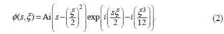
    Since Eq. (2) is not square-integrable, an aperture function exp(as) is necessary to tailor infinite side lobes for experimental realization of Airy beams. Thus at the origin (z=0) the form of the Airy beam is given by

    image

    where a is positive. It is clear that the more a deviates from zero, the more the energy of this beam (called a finite Airy beam) is confined, while the beam becomes analogous to an ideal Airy beam as a approaches zero [10].

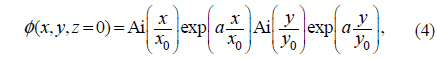
    In the case of a (2+1)-dimensional ((2+1)D) finite Airy beam, Eq. (3) can be expanded to

    image

    where x0 and y0 are arbitrary scaling factors along the x and y coordinates respectively. Throughout this paper, the parameters of the finite Airy beams (x0, y0, and a) are set to 50 μm, 50 μm, and 0.1 respectively, and a wavelength of 633 nm is assumed. We can see the intensity distributions of the (2+1)D finite Airy beam with these parameters at positions z=0, z=5 cm, and z=15 cm in Figs. 1(a), 1(b), and 1(c), respectively.

    III. HOLOGRAPHIC RECORDING AND RECONSTRUCTION OF AIRY BEAMS

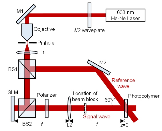
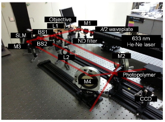
    Holography is a technique that can record and reconstruct both the amplitude and the phase of an optical wave [19]. Figure 2 is a schematic diagram of the recording procedure for holographic generation of an Airy beam. After passing through expanding optics and a beam splitter 1 (BS1), a plane wave from a He-Ne laser (Research Electro-Optics, LSRP-3501) with wavelength 633 nm is divided into signal and reference arms. The signal arm is consisted of a 2-f system: a spatial light modulator (SLM) (Holoeye Pluto, reflection type, 1920 × 1080 pixels, pixel pitch 8 μm) that imposes cubic phase, and lens 2 (L2) with a focal length f of 50 cm [20]. We place L2 at a distance f from the SLM to perform the optical Fourier transform. A λ/2 wave plate and linear polarizer are used to adjust the polarization states and obtain clear images respectively. After the signal beam is reflected from the SLM and travels f after passing through L2, i.e. at the Fourier plane (which is taken as z=0), a finite Airy beam is obtained

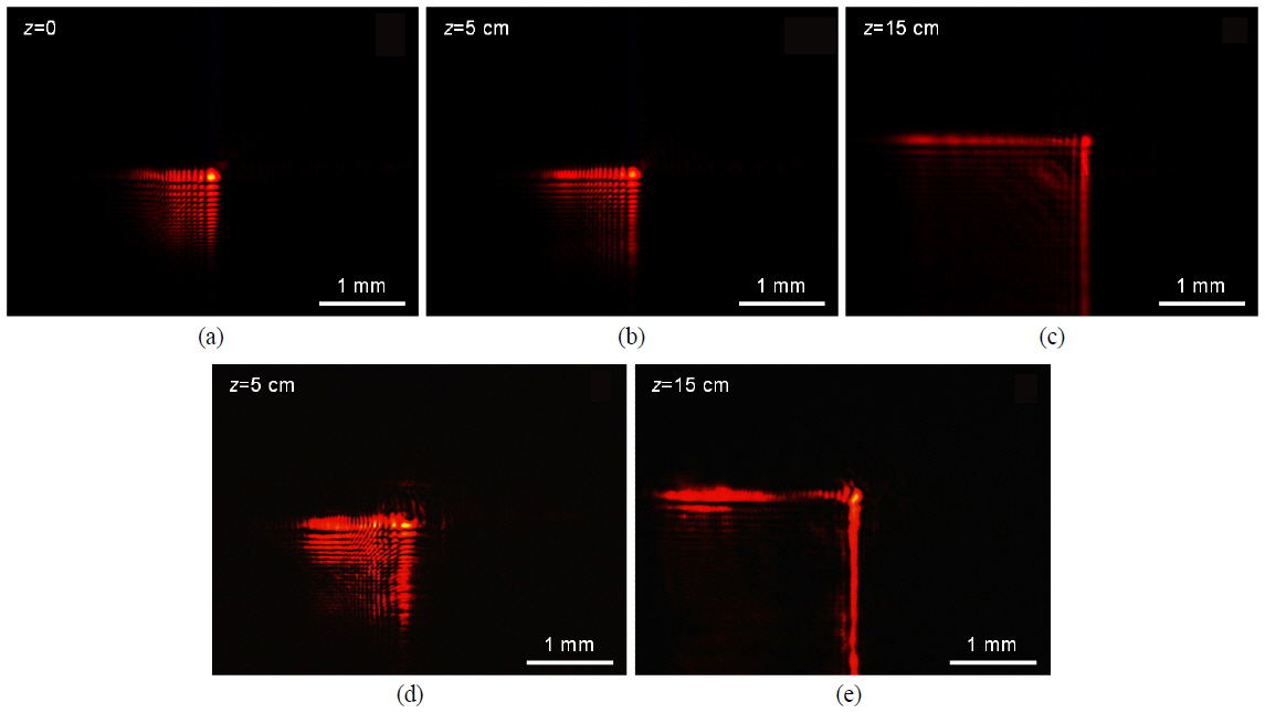
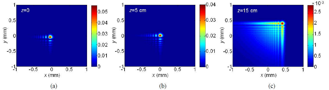
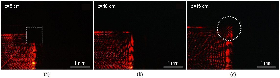
    Before actually recording, we confirm that the signal beam is the desired finite Airy beam using a charge-coupled device (CCD). We use a first-order diffracted beam from the SLM for Airy beam generation and hologram recording, to avoid the DC term in the zeroth-order diffracted Airy beam. The captured images (without photopolymer) of a (2+1)D finite Airy beam at z=0 (at the Fourier plane), z=5 cm, and z=15 cm are shown in Figs. 3(a), 3(b), and 3(c), respectively. After this, interference patterns between signal and reference (a plane wave) beams are recorded on photo-polymer film [21]. In this procedure, the reference beam has an incident angle of 60° with an exposed energy of 32 mJ/cm2. The photopolymer film, which is laminated on a slide glass (refractive index 1.518) consists of two layers: a photopolymer layer of thickness ranging from 14 to 18 μm and optically clear plastic substrate layer (refractive index 1.57) of 175 μm thickness. The refractive index of the photopolymer layer before the hologram recording is 1.485, and the maximum value of refractive index modulation is 0.03 with 633-nm illumination. We select this material because it is easy to handle, and the post-exposure processing is quite simple. For curing, the recorded sample is exposed to a UV lamp with a power density of 110 mW/cm2 for 3 minutes, the distance between lamp and sample being kept to about 30 cm.

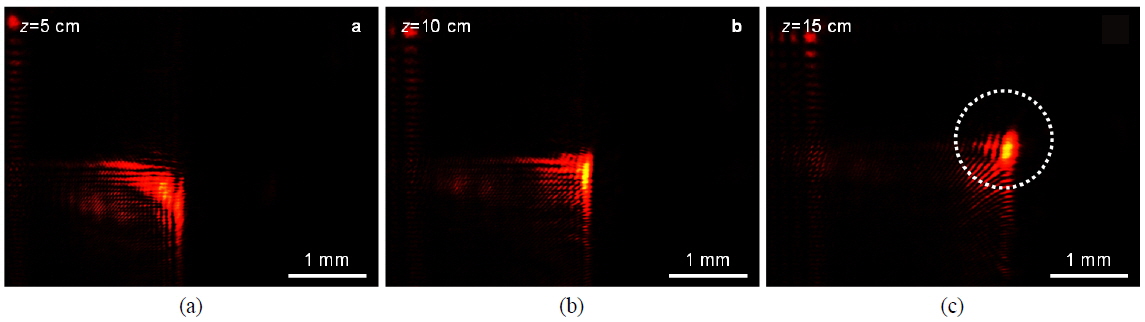
    To reconstruct the Airy beam, we place a beam blocker (indicated as a dotted box in Fig. 2) in the signal-beam path, to shine the reference beam without a signal beam. As a result, the signal beam, i.e. the (2+1)D finite Airy beam, is simply generated from the photopolymer without any SLM or lens optics. Captured intensity distributions of the reconstructed beam at z=5 cm and z=15 cm are shown in Figs. 3(d) and 3(e) respectively. Here we cannot present the intensity pattern of the reconstructed beam at z=0, because the CCD camera cannot be placed in front of the photopolymer surface. Comparing Figs. 3(d) and 3(e) to Figs. 1(b) and 1(c), or Figs. 3(b) and 3(c), we can see that the reconstructed beam shows intensity distributions similar not only to those of the calculated Airy beam, but also to those of the SLM-generated (signal) Airy beam. In addition, after propagating 15 cm in the +z-direction they still coincide well, as shown in Figs. 1(c), 3(c), and 3(e). These results show that the reconstructed beam is a holographically generated Airy beam retaining the same characteristics of the original Airy beam, such as acceleration and non-diffraction.

    To provide a quantitative analysis of the propagation behaviors of SLM-generated Airy beams and reconstructed Airy beams, cross-correlations with the ideal Airy beam are calculated from the cross-sections of the main lobes along the
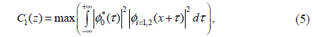
 x-direction at z=5 cm and z=15 cm, respectively. We define the maximum value of the cross correlation C1(z) as follow:

    image

    where ϕ0 is the ideal Airy beam, ϕ1 is the SLM generated Airy beam, and ϕ2 is the reconstructed Airy beam. When C1(z) between the ideal Airy beam and the reconstructed Airy beam is normalized to that of the SLM-generated Airy beam, the values of C1(z) are 0.79 (z=5 cm) and 0.63 (z=15 cm) respectively.

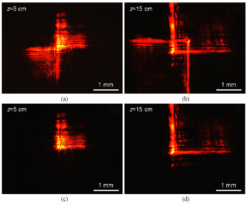
    As another confirmation, we can check whether the holographically reconstructed beam has the self-healing feature [11], a distinguishing property of various types of diffractionfree beams. Here we consider two cases of self-healing in the reconstruction procedure. First, an opaque obstacle is placed between the photopolymer and the z=5 cm plane, to block the main lobe of the reconstructed beam. The location of the obstacle is indicated in Fig. 4(a) as a white box. This veiled main lobe is, however, reconstructed after the propagation distance of 15 cm, as indicated by the white circle in Fig. 4(c). That is, although the main lobe of the generated beam is blocked, its original shape can be reconstructed during propagation; thus the holographically generated Airy beam has the self-healing characteristic, as expected.

    As a second case, we partially block the reference beam with an obstacle placed between M2 and the photopolymer, to achieve partial illumination of the recorded medium. The CCD image of the reconstructed beam at z=5 cm is shown in Fig. 5(a). Similar to the first case shown in Fig. 4, after propagating 10 or 15 cm the reconstructed beam recovers its original Airy shape, as can be seen in Fig. 5(c), indicated as a white circle. Although the self-healed Airy beams in both Figs. 4 and 5 have decreased energy due to the beam blocking, the results show that the main lobes of the holographically generated Airy beams are recovered. This means that robust reconstruction of the original information (self-healing) can be realized, even if significantly imperfect incidence occurs for the reference beam.

    IV. ANGULAR MULTIPLEXING OF AIRY BEAMS

    Finally, we investigate the feasibility of angular multiplexing of Airy beams based on holography. In this case the recording procedure is conducted twice, with two reference beams at different incidence angles. In Fig. 6 the experimental setup for Airy beam multiplexing is presented. Two reference beams are incident to the photopolymer with 60° and −60° incidence angles respectively, and energy density of 32 mJ/cm2 is dosed as in the previous section. To compensate for the power difference between two reference beams, a neutral density (ND) filter is located in reference arm 1. Here reference arms 1 and 2 pass through M2 and M4 respectively. First, a (2+1)D finite Airy beam with x0=50 μm and y0=50 μm is recorded on the photopolymer, while opening reference arm 1 and blocking reference arm 2. Next, another (2+1)D finite Airy beam with x0=−50 μm and y0=−50 μm is recorded in the same area of the photopolymer, while opening only reference arm 2. Each Airy beam propagates with a different acceleration direction when both signal Airy beams are successively recorded on the same area of the photopolymer with the respective reference beams.

    To reconstruct recorded Airy beams, we place an additional barrier between lens and photopolymer, to block the signal beam. After that, two reference beams are incident upon the photopolymer at the same time, and we obtain two Airy beams accelerating in opposite directions, as shown in Figs. 7(a) and 7(b), which are captured by the CCD at z=5 cm and z=15 cm respectively. Moreover, when we block only reference arm 1 we can reconstruct only one Airy beam, as shown in Figs. 3(d) and 3(e), which are captured at z=5 cm (Fig. 7(c)) and z=15 cm (Fig. 7(d)) respectively. That is, each Airy beam can be individually controlled via appropriate blocking of a reference beam. This can be utilized for on/off switching or routing in optical signal processing. Also, it can be applied to particle manipulation: a portion of particles can be held or released while others are released or held, respectively.

    V. CONCLUSION

    In this paper, a novel Airy beam generation method based on holography is presented. The proposed method has the advantage that once holograms are recorded in the photopolymer, bulky optics such as SLM and lenses are not needed to generate Airy beams. In addition, multiple Airy beams can be stored and reconstructed simultaneously or individually. We hope that these results find practical uses, such as in particle manipulation or optical signal processing [14-18].

참고문헌
  • 1. Berry M., Balazs N. 1979 “Nonspreading wave packets,” [Am. J. Phys.] Vol.47 P.264-267 google cross ref
  • 2. Siviloglou G. A., Christodoulides D. N. 2007 “Accelerating finite energy Airy beams,” [Opt. Lett.] Vol.32 P.979-981 google cross ref
  • 3. Siviloglou G. A., Broky J., Dogariu A., Christodoulides D. N. 2007 “Observation of accelerating Airy beams,” [Phys. Rev. Lett.] Vol.99 P.213901 google cross ref
  • 4. Ellenbogen T., Voloch-Bloch N., Ganany-Padowicz A., Arie A. 2009 “Nonlinear generation and manipulation of Airy beams,” [Nat. Photon.] Vol.3 P.395-398 google cross ref
  • 5. Polynkin P., Kolesik M., Moloney J. V., Siviloglou G. A., Christodoulides D. N. 2009 “Curved plasma channel generation using ultraintense Airy beams,” [Science] Vol.324 P.229-232 google cross ref
  • 6. Voloch-Bloch N., Lereah Y., Lilach Y., Gover A., Arie A. 2013 “Generation of electron Airy beams,” [Nature] Vol.494 P.331-335 google cross ref
  • 7. Choi D., Lim Y., Lee I.-M., Roh S., Lee B. 2012 “Airy beam excitation using a subwavelength metallic slit array,” [IEEE Photon. Technol. Lett.] Vol.24 P.1440-1442 google cross ref
  • 8. Zhang P., Wang S., Liu Y., Yin X., Lu C., Chen Z., Zhang X. 2011 “Plasmonic Airy beams with dynamically controlled trajectories,” [Opt. lett.] Vol.36 P.3191-3193 google cross ref
  • 9. Choi D., Hong K., Lee K., Cho J., Lee I.-M., Lee B. 2013 “Airy beam generation based on holographic recording and reconstruction,” [Proc. Digital Holography and Three-Dimensional Imaging, OSA Technical Digest] google
  • 10. Choi D., Lee K., Hong K., Lee I.-M., Kim K.-Y., Lee B. 2013 “Generation of finite power Airy beams via initial field modulation,” [Opt. Express] Vol.21 P.18797-18804 google cross ref
  • 11. Broky J., Siviloglou G. A., Dogariu A., Christodoulides D. N. 2008 “Self-healing properties of optical Airy beams,” [Opt. Express] Vol.16 P.12880-12891 google cross ref
  • 12. Siviloglou G. A., Broky J., Dogariu A., Christodoulides D. N. 2008 “Ballistic dynamics of Airy beams,” [Opt. Lett.] Vol.33 P.207-209 google cross ref
  • 13. Hwang C.-Y., Choi D., Kim K.-Y., Lee B. 2010 “Dual Airy beam,” [Opt. Express] Vol.18 P.23504-23516 google cross ref
  • 14. Baumgartl J., Mazilu M., Dholakia K. 2008 “Optically mediated particle clearing using Airy wavepackets,” [Nat. Photon.] Vol.2 P.675-678 google cross ref
  • 15. Christodoulides D. N. 2008 “Optical trapping: Riding along an Airy beam,” [Nat. Photon.] Vol.2 P.652-653 google cross ref
  • 16. Zhang P., Prakash J., Zhang Z., Mills M. S., Efremidis N. K., Christodoulides D. N., Chen Z. 2011 “Trapping and guiding microparticles with morphing autofocusing Airy beams,” [Opt. Lett.] Vol.36 P.2883-2885 google cross ref
  • 17. Zheng Z., Zhang B.-F., Chen H., Ding J., Wang H.-T. 2011 “Optical trapping with focused Airy beams,” [Appl. Opt.] Vol.50 P.43-49 google cross ref
  • 18. Rose P., Diebel F., Boguslawski M., Denz C. 2013 “Airy beam induced optical routing,” [Appl. Phys. Lett.] Vol.102 P.101101 google cross ref
  • 19. Goodman J. 2005 Introduction to Fourier Optics google
  • 20. Khos-Ochir T., Munkhbaatar P., Yang B., Kim H., Kim J., Kim M. 2012 “Polarimetric measurement of Jones matrix of a twisted nematic liquid crystal spatial light modulator,” [J. Opt. Soc. Korea] Vol.16 P.443-448 google cross ref
  • 21. Lee K, Jeung S., Cho B., Kim N. 2012 “Photopolymer-based surface-normal input/output volume holographic grating coupler for 1550-nm optical wavelength,” [J. Opt. Soc. Korea] Vol.16 P.17-21 google cross ref
OAK XML 통계
이미지 / 테이블
  • [ ] 
  • [ ] 
  • [ ] 
  • [ ] 
  • [ FIG. 1. ]  Intensity distributions of a (2+1)D finite Airy beam at (a) z=0, (b) z=5 cm, and (c) z=15 cm.
    Intensity distributions of a (2+1)D finite Airy beam at (a) z=0, (b) z=5 cm, and (c) z=15 cm.
  • [ FIG. 2. ]  Schematic diagram of the recording and reconstruction procedures for the holographic generation of an Airy beam.
    Schematic diagram of the recording and reconstruction procedures for the holographic generation of an Airy beam.
  • [ FIG. 3. ]  CCD images of the signal beam (a (2+1)D finite Airy beam) at (a) z=0, (b) z=5 cm, and (c) z=15 cm, plus CCD images of the holographically reconstructed Airy beam at (d) z=5 cm and (e) z=15 cm.
    CCD images of the signal beam (a (2+1)D finite Airy beam) at (a) z=0, (b) z=5 cm, and (c) z=15 cm, plus CCD images of the holographically reconstructed Airy beam at (d) z=5 cm and (e) z=15 cm.
  • [ ] 
  • [ FIG. 4. ]  (a) A holographically generated Airy beam that is blocked at z=5 cm. Its intensity patterns (CCD images) at (b) z=10 cm and (c) z=15 cm clearly demonstrate the self-healing characteristic of a holographically generated beam.
    (a) A holographically generated Airy beam that is blocked at z=5 cm. Its intensity patterns (CCD images) at (b) z=10 cm and (c) z=15 cm clearly demonstrate the self-healing characteristic of a holographically generated beam.
  • [ FIG. 5. ]  Beam reconstruction for the case of partial incidence of the reference beam. Profiles of reconstructed beams captured at (a) z=5 cm, (b) z=10 cm, and (c) z=15 cm. The white circle denotes the main lobe (veiled) region.
    Beam reconstruction for the case of partial incidence of the reference beam. Profiles of reconstructed beams captured at (a) z=5 cm, (b) z=10 cm, and (c) z=15 cm. The white circle denotes the main lobe (veiled) region.
  • [ FIG. 6. ]  Experimental setup for Airy-beam multiplexing (M: mirror, L: lens, BS: beam splitter).
    Experimental setup for Airy-beam multiplexing (M: mirror, L: lens, BS: beam splitter).
  • [ FIG. 7. ]  CCD images of reconstructed multiple Airy beams at (a) z=5 cm and (b) z=15 cm, plus reconstructed Airy beams at (c) z=5 cm and (d) z=15 cm when reference beam 1 is blocked.
    CCD images of reconstructed multiple Airy beams at (a) z=5 cm and (b) z=15 cm, plus reconstructed Airy beams at (c) z=5 cm and (d) z=15 cm when reference beam 1 is blocked.
(우)06579 서울시 서초구 반포대로 201(반포동)
Tel. 02-537-6389 | Fax. 02-590-0571 | 문의 : oak2014@korea.kr
Copyright(c) National Library of Korea. All rights reserved.