More than one hundred CubeSats have been placed in orbit since the first launch of a CubeSat in 2003 (Swartwout 2013). CubeSats have been proven to allow for extremely low-cost missions in near Earth orbits with greater launch accessibility. As a result, ideas for applying CubeSat technology to deep space exploration concepts have greatly increased (Klesh & Castillo-Rogez 2012). Recently, the NASA Innovative Advanced Concepts (NIAC) program selected interplanetary CubeSats for further investigation in order to enable a new class of missions beyond low Earth orbits (Blaney et al. 2012). The potential missions initially considered by NIAC are: Mineral Mapping of an Asteroid, Solar System Escape Technology Demonstration, Earth-Sun Sub-L1 Space Weather Monitor, Phobos Sample Return, Earth-Moon L2 Radio Quiet Observatory, and Out-of-Ecliptic Missions (Staehle et al. 2013). In addition to these missions, NASA is considering launching a CubeSat-based payload on a future Mars exploration mission around 2016 to early 2020’s using excess capacity on the mission’s primary spacecraft (Komarek et al. 2013). Recently, the Jet Propulsion Laboratory (JPL) selected and funded CubeSat concept studies for the NASA mission Europa Clipper, of which a mission is aimed for launch around 2025 with multiple CubeSats. Scientific objectives for the released CubeSats in the Jovian system would include determining reconnaissance for future landing sites, gravity fields, magnetic fields, atmospheric and plume conditions, and radiation levels in order to enhance our understanding of Europa (JPL 2013). Over the coming decade, it is expected that diverse scientific information could be obtained from extremely low-cost solar system exploration missions with improved CubeSat technologies that are beyond those that have been demonstrated to date (Staehle et al. 2013).
Since 1992, Korea has been continuously operating more than ten Earth-orbiting satellites and is now expanding its interests to planetary missions. The Korean space program has plans to launch a lunar orbiter and lander around 2020, and also has plans to explore Mars, asteroids, and deep space in the future. Therefore, the Korean aeronautical and space science community has performed numerous related mission studies, and the Korea Aerospace Research Institute (KARI) is performing pre-phase work for the lunar mission. Several preliminary design studies have already been conducted, such as an transfer trajectory analysis (Song et al. 2009, 2011; Woo et al. 2010), contact schedule analysis (Song et al. 2013, 2014), rover system design (Kim et al. 2009, Eom et al. 2012). For the lunar orbiter mission, the Korean lunar science committee is now working to select the main scientific objectives. One of the candidates is to fly a CubeSat impactor to explore lunar magnetic anomalies and associated albedo features, known as swirls (Lee et al. 2014). In 1959, the Soviet spacecraft called “Luna-1” carried a magnetometer to the Moon. Observation data from “Luna-1”concluded that the Moon has no global magnetic field like the Earth. However, from the Apollo 15 and 16 missions, it was discovered that strongly magnetized materials are distributed all over the Moon’s crust. The origin of lunar magnetism is one of the oldest problems that is still being debated in the field of lunar science (Garrick-Bethell et al. 2013). Understanding the origin of swirls may help to understand not only geological processes, but also space weathering effects on the lunar surface. Although previous lunar missions such as NASA’s Lunar Prospector and JAXA’s KAGUYA also measured lunar magnetic fields, these data are not enough to completely characterize the magnetic anomaly region because they were obtained at high altitudes (>20 km) above the lunar surface (Garrick-Bethell et al. 2013). For this reason, a new idea proposes to use a CubeSat carrying a magnetometer as a payload to impact the target region of interest. The concept of using a CubeSat impactor to measure lunar magnetic fields near the surface has already been discussed by Garrick-Bethell et al. (2013). In the literature by Garrick-Bethell et al. (2013), two major lunar transfer scenarios are proposed to deliver the CubeSat impactor. The first option is to use the Planetary HitchHiker (PHH) concept, which involves a small spacecraft designed to be accommodated as a secondary payload on a variety of launch vehicles. In this concept, the launch vehicle places the PHH spacecraft into Geostationary Transfer Orbit (GTO) to reduce mission costs. Following insertion into GTO, the PHH spacecraft uses onboard propulsion to cruise to the Moon and, finally, releases the CubeSat impactor after appropriate orbital conditions are established. Appropriate orbital conditions to deploy the CubeSat impactor will be established by several Lunar Orbit Insertion (LOI), orbit adjustment, and station-keeping burns as is done during conventional lunar mission sequences. The second concept involves boarding the CubeSat impactor into a geostationary spacecraft as a payload and deploying it after reaching geostationary orbit (GEO). The released impactor will spiral out to the Moon with its own minimized ion propulsion system and upon entering the Moon’s gravitational sphere of influence, the CubeSat will directly impact the target area without entering the lunar orbit. However, these two mission scenarios have several challenging aspects to overcome; longer flight times to reach the lunar orbit (which is expected to be more than 100 days), tolerating large amounts of radiation exposure even though the mission starts from GEO, and, most importantly, establishing a shallow impact angle (<10 deg) during the impact phase to meet the science objectives, which is a more critical factor if a mother-ship is not used (Garrick-Bethell et al. 2013).
Another promising method to achieve this mission objective might be to fly the lunar CubeSat impactor as one of the scientific payloads on the lunar orbiter. We believe that this approach will partly ease the challenging aspects that have been raised in the previously discussed scenarios, especially for establishing very shallow impact angles. Indeed, one of the major expected contributions of using CubeSats in planetary missions is that a large variety of near-surface scientific experiments could be performed (Klesh & Castillo-Rogez 2012). Most of planetary exploration to date has been performed through remote sensing from orbiters or by surface exploration using landers. However, such methods are expensive and risky and the scientific data gathered from near-surface can be limited (Klesh & Castillo-Rogez 2012). For these reasons, and as previously discussed, CubeSat-based payload planetary missions are vigorously promoted not only for the Moon, but also for Mars, Europa and other deep space exploration missions. Recently, Song et al. (2015) analyzed CubeSat impact trajectory characteristics as a function of its release conditions from a mother-ship orbiting the Moon at about a 100 km altitude. They also analyzed relative motions between the CubeSat and the mother-ship during the impact phase. From Song et al.’s (2015) work, it is found that a very shallow impact angle (less than 10 deg) could be achieved by releasing the CubeSat from a 100 km altitude. However, the amount of required divert delta-V magnitude to have the CubeSat to impact the lunar surface is found to be quite large compared with the capabilities of the currently available Poly Picosatellite Orbital Deployer (P-POD) system. This means that a CubeSat on-board thruster is necessary to achieve the impact trajectory. Furthermore, required divert delta-V’s with different CubeSat release altitudes should be further analyzed for diversities of mission analysis.
Therefore, impact trajectory characteristics and their dependence on release conditions from a mother-ship having different orbital altitudes are analyzed in the current work. Also, based on the derived delta-V requirements, required thruster burn time and fuel mass are analyzed by adapting four different miniaturized commercial onboard thrusters currently developed for CubeSat applications. The authors believe that these preliminary impact trajectory design studies will be helpful for further detailed system definition and design activities. In Section 2, system dynamics to establish the CubeSat impact problem is described in order to simulate a given impactor mission. Numerical assumptions made for the simulation are discussed in Section 3. Detailed analysis results are provided in Section 4 including impact trajectory characteristics as a function of deployment altitude and divert burn characteristics for different onboard thrusters. In Section 5, conclusions are made. Although the current analysis only considers a lunar CubeSat impactor mission, the methods discussed herein can easily be modified and applied to other similar missions where CubeSats are released from a mother-ship orbiting around another planet or moon, and will certainly have broad implications for future planetary missions involving CubeSats.
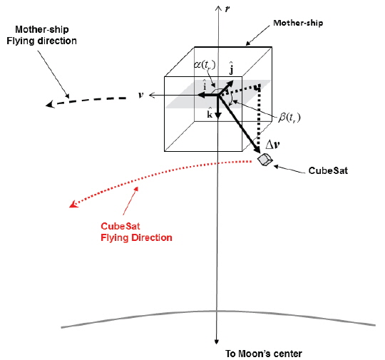
Two body equations of motion of the CubeSat impactor released from a mother-ship are expressed as:

with initial conditions

where

where Δ

where subscripts
After separation from the mother-ship, the deploy conditions that leads the CubeSat to impact the lunar surface can be selected using the method described by Brent (2002) which find the root of numerically integrated single nonlinear equation. During the root-finding process, the objective function,

By utilizing Eq. (5), the CubeSat impactor’s closest approach time to the lunar surface,
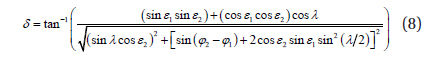
After the computed trajectory is found to be the impact cases, then, the CubeSat impact angle,

where
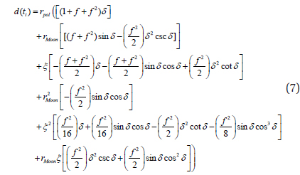
In Eq. (7),


For the CubeSat onboard thruster, the required burn duration during the divert phase,

where

The approximated mass after burnout,
To simplify the given problem so as to focus on early design phase analysis, several assumptions are made during the simulations. As previously discussed, two-body equations of motion are used to simulate both the mother-ship and the CubeSat impactor. Divert delta-V is assumed to be an impulsive burn for the CubeSat impactor separation. For numerical integration, a Runge-Kutta-Fehlberg 7-8th order variable step size integrator is used with a truncation error tolerance of
4.1 Impact Trajectory Characteristics Deployed from Different Altitudes
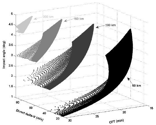
In this sub-section, the characteristics of CubeSat impact trajectories as a function of its release conditions (divert delta-V and out-of-plane direction release angle) for four different altitudes (50, 100, 150 and 200 km) are analyzed. Critical design parameters that are directly related to the success of the mission are also analyzed including the CFT, impact velocity, and impact angles. In Fig. 3, the characteristics of CFTs as a function of deploy delta-V magnitude and out-of-plane deploy direction angle are shown at four different release altitudes. Note that CFT is numerically determined with the conditions shown in Eq. (5), and the deploy delta-V magnitude for both out-of and in-plane deploy direction angles are given arbitrary values as discussed in the previous section. Impact velocity is directly derived by numerically integrating the CubeSat impact trajectory. Characteristics of the CubeSat impact angle (derived using Eq. (6)) as a function of divert delta-V magnitude and CFT are also shown in Fig. 4. In this simulation, cross-range distance (Eq. (7)) is computed at the sub-satellite point where the CubeSat is released (
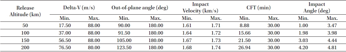
From Fig. 3, it can be concluded that the higher the release altitude, the more deploy delta-V is required to release the CubeSat in order to impact the lunar surface. As the release altitude increases, acceptable out-of-plane deployment ranges become narrower. The resultant CFT also exhibit higher values at these narrower boundaries. These results indicate that release conditions of smaller values are possible in order to meet the science objectives if the CubeSat is released at higher altitudes. For example, it is certain that releasing the CubeSat at a 50 km altitude has more opportunities for impact than when released from a 200 km altitude as the 50 km case has wider ranges of divert delta-Vs, out-of-plane angle release directions, and CFTs. Less divert delta-Vs and wider ranges of CTF will certainly ease the design process of the onboard propulsion system as they are directly related to the size of the propulsion system. For impact angle characteristics, regardless of release altitude, the mission requirements were satisfactorily achieved as they all remained less than 4.81 degs. Taking the impact angle as the major design parameter, it seems that a CubeSat release at a 200 km altitude would be the most effective choice as this angle shows greater impact angle ranges (4.20 ~ 4.81 degs) as compared with releases from other altitudes (1.00 ~ 3.47 degs for 50 km release case, for example). In addition, a 200 km release altitude can partially avoid the uncertainties inherent lunar surface heights. However, as seen in Fig. 3, it should be noted that releasing the CubeSat from a 200 km altitude requires a higher deploy delta-V magnitude (76.5 ~ 88.0 m/s) than at other heights. These values in these ranges are quite large to be supported by the onboard thruster of the CubeSat for given CFTs. Careful trade-off studies should therefore be made in future analyses to select the most appropriate candidate for the onboard thrusters. In Table 1, detailed characteristics of the obtained CubeSat impact trajectories are summarized including minimum and maximum values of deploy delta-Vs, out-of-plane angle, CFT, impact velocity and impact angles. From Table 1, variation tendencies in CubeSat impact trajectories at different release altitudes can be easily observed.

Detailed design parameters for the obtained CubeSat impact trajectories at different orbital release altitudes.
4.2 Divert Burn Characteristics for Different onboard Thrusters
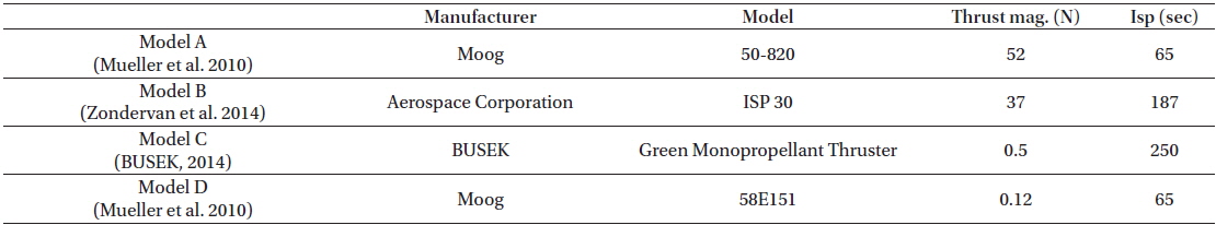
As the capabilities of the CubeSat missions are increasing, such as orbit raising, orbital plane change, formation flying, fine attitude control, proximity operation, and deorbit, onboard propulsion capabilities for the CubeSat are becoming a more crucial factor for the success of the mission. Indeed, there exist various options that can be used for the onboard CubeSat thrusters, including monopropellants, bipropellants, solid propellants with cold gas for chemical thrusters, vacuum arc, micro scale retro jets, micro pulsed plasma, and micro colloid for electric thrusters (Storck et al. 2006). Aside from these thrusters, readers can find numerous propulsion systems that are possible for CubeSats in Mueller et al. (2010). Based on the divert delta-V characteristics previously derived, this subsection analyzes divert burn characteristics such as required burn time and fuel mass using four arbitrarily selected CubeSat onboard thrusters. Four different miniaturized onboard thrusters commercially developed for CubeSat applications are considered and are shown in Table 2. Selection of onboard thruster is made by trial and error during the simulation to not only to provide a wide range of thrust magnitude but also to obtain meaningful results under the divert delta-Vs obtained previously. For the following discussions, fuel mass and burn time fraction are computed through (

Characteristics of four different miniaturized onboard thrusters used for this simulation.
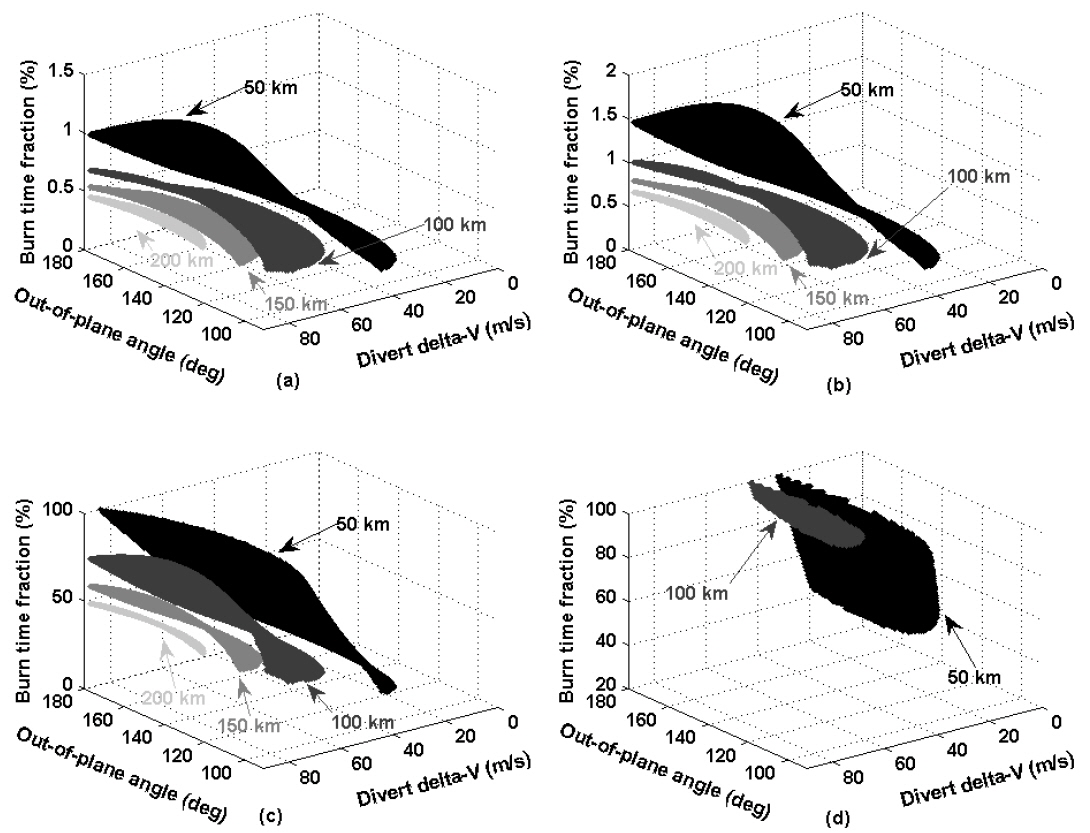
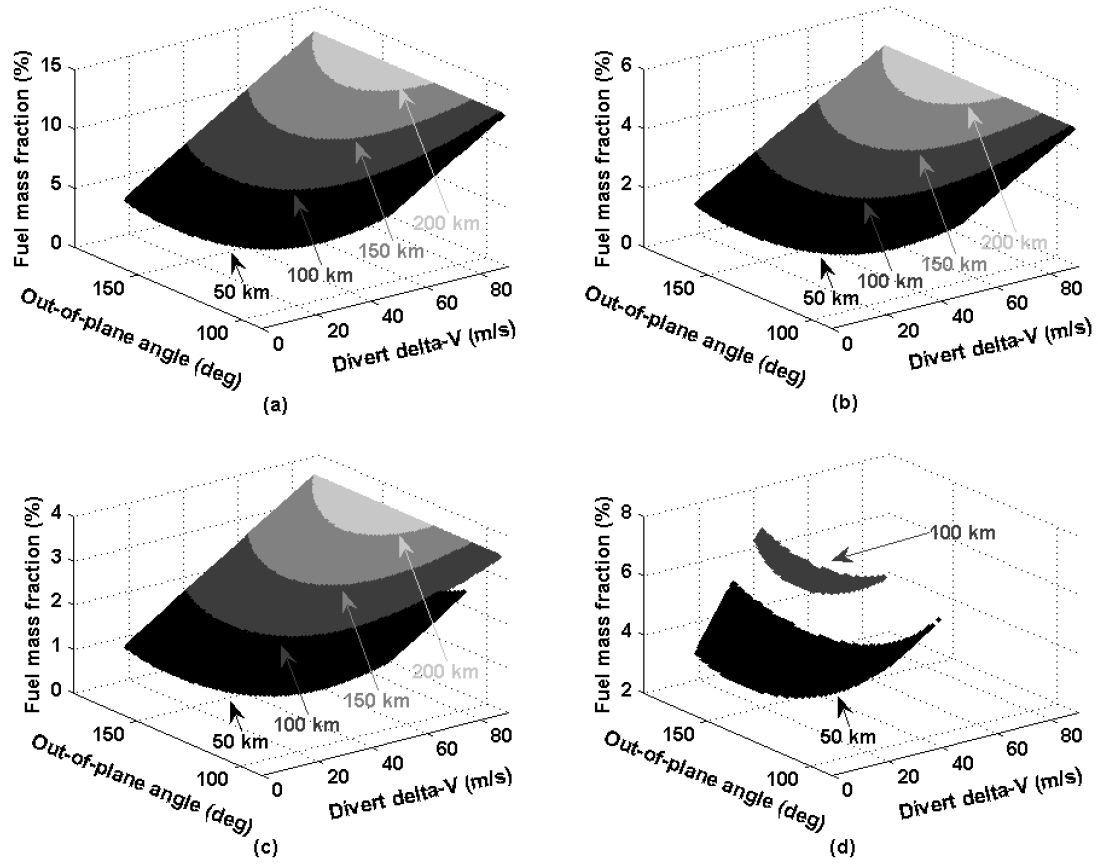
In Fig. 5, burn time fraction characteristics as a function of divert delta-V and out-of-plane release angle for four different deployment altitudes are shown for four different onboard thruster model. Figs. 5(a)-5(d) correspond to the onboard thruster models A, B, C, and D, respectively, listed in Table 2. With thruster models A and B, it is possible to impact the lunar surface within a required CTF at each altitude (50, 100, 150 and 200 km). Deployed and burn time fraction is found to be about 0.12~1.48% for thruster model A and 0.17~2.18% for the thruster model B. This indicates that an engine burn duration of only 2% of the entire CFT is necessary during the CubeSat impact phase if a thruster is used that has similar performance to those of the selected thrusters. However, with thruster model C, burn time fraction reaches up to about 99.99% for the 50 km altitude deployment case as shown in Fig. 5(c). This means that the onboard thruster would have to be turned on for the entire duration of the lunar impact phase. Running the thruster during the entire impact phase could lead to serious difficulties in attitude control strategy of the CubeSat and could also affect the qualities of science data gathered. Similarly, burn time fraction with thruster model D also reaches 100%. It is found that only the 50 and 100 km altitude deployed cases are partially available to impact the lunar surface. Therefore, CubeSats deployed from 150 and 200 km altitudes with thruster model D are not able to impact the lunar surface as every required delta-V cannot be supported within the required CFTs. As clearly shown in Fig. 5(d), very limited ranges of divert delta-V can be covered with thruster model D. From the burn time fraction point of view, it seems that an onboard thruster’s performance equivalent to those of model A, B and C would be acceptable for future lunar CubeSat impactor missions. However, achieving the target impact point with models A and B would be more critical than with the model C. This is because fine targeting of the impact point through higher thrust levels would very difficult to achieve requiring complex thruster on-off strategies resulting in an increase in complexity of the CubeSat operation concept. Therefore, it seems that having an onboard thruster whose performance is equivalent to or slightly better than that of model C will more be preferable as every CubeSat deployment altitude (except minor part of 50 km release case) can be covered with reasonable burn time fractions, roughly about 50%, with thruster model C. The authors believe that securing an appropriate free flight path during the impact phase will be critical for the success of the mission as a constant thruster burn during most of the impact phase could lead to not only serious difficulties in attitude control but also could affect the qualities of science data gathered due to the disturbances. Similarly for those in Fig. 5, fuel mass fraction characteristics are analyzed and depicted in Fig. 6. Figs. 6(a)-6(d) correspond to thruster models A, B, C, and D, respectively. Regardless of deployment altitude and onboard thruster, the fuel mass fractions remained within the ranges of 2.71~12.89% with thruster model A, 0.95~4.69% with model B, 0.71~3.52% with model C, and 2.71~6.67% with model D. The maximum obtained fuel mass fraction is about 12.89% when deployed from a 200 km altitude with thruster model A, which is only about 0.64 kg out of the CubeSat’s total 5 kg mass. With thruster model C, it is found that only about 0.17 kg of fuel is necessary to accomplish the impact mission with a suitable burn time fraction. Detailed mission parameters derived for each onboard thruster is summarized in Table 3. From the previous burn time and fuel mass fraction analyses, it can be concluded that during the design stage of the onboard thrusters for a CubeSat lunar impact mission, thrust burn time should be more critically considered as a design parameter than the required fuel mass for the impact phase of the mission.

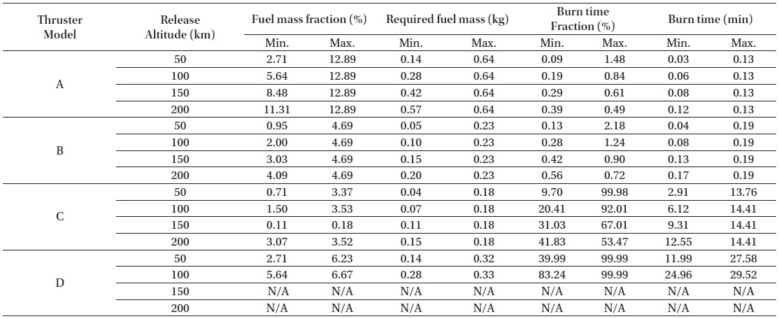
Detailed design parameters for selected onboard thrusters for different orbital deployment altitudes. Assumed overall CubeSat mass to be 5 kg.
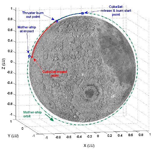
An example of an impact trajectory is shown in Fig. 7. In this example, the CubeSat is assumed to be released at an altitude of 100 km with an 180 deg out-of-plane angle and 60 m/s divert delta-V. Thruster model C is assumed to be installed. In the figure, the trajectories are shown with the normalized distance unit, Lunar Unit (LU), where 1 LU is approximately 1,738.2 km. For the actual flight, some time gaps may be required between the moment of the CubeSat separation and the ignition of onboard thruster for mission safety. For this study, however, the onboard thruster is assumed to be turned-on just after the CubeSat separation. For this example, it is found that about 24.50 min of CFT is required to impact the lunar surface with an impact velocity and angle of about 1.67 km/s and 2.57 deg, respectively. With the model C onboard thruster, about 9.55 min of burn duration out of 24.50 min of CFT is necessary to satisfy the delta-V required for successful lunar surface impact, which is about 38.98% of burn time. As shown in Fig. 7, for the remaining 41.02% of the impact phase, the CubeSat will freely fly towards the lunar surface with the thruster off. During this phase, science data gathering could be done with less disturbances that can affect the quality of the data. Additionally, about 0.12 kg of fuel is required with this thruster model. From the assumed overall CubeSat mass of 5 kg, the final mass of the CubeSat after the burn will be about 4.88 kg, resulting in a fuel mass fraction of about 2.34%.
As a part of early system design activities for a lunar CubeSat impactor mission, this study analyzes characteristics of delta-V requirements in order to deploy an impactor from a mother-ship orbiting the Moon with a circular orbit, 90 deg inclination, and having different orbital altitudes (50, 100, 150, 200 km). Along with delta-V requirements, deploy directions, CubeSat flight time, impact velocity, and associated impact angles are also analyzed. Required onboard thruster burn time and required fuel mass are analyzed as well by adapting four different miniaturized commercial onboard thrusters currently developed for CubeSat applications. As a result, it is discovered that if the CubeSat is released at higher altitudes, lesser release conditions are achievable to meet the mission objectives. This is due to the fact that deploying at higher altitudes require more deploy delta-V, limited ranges of out-of-plane deploy angle, and longer CubeSat flight time. However, high altitude deployment of the CubeSat can partially avoid the uncertainties bared in lunar surface heights as a result of the higher impact angle as compared with the lower altitude deployment cases. From deployment burn characteristics analysis results, it is estimated that an onboard thruster having a performance equivalent to about 0.5 N of thrust and with an Isp of 250 sec (slightly better will more be preferable) would be acceptable for the future lunar CubeSat impactor mission having 5 kg of overall mass. For this case, a maximum of about 0.18 kg of fuel is required to impact the CubeSat regardless of deployment altitude. With an onboard thruster of this performance, burn time fraction was found to be roughly about 50% of the 30 min total CubeSat flight time. This indicates that the CubeSat can freely fly toward the lunar surface with the thruster turned off for almost half of its entire impact phase. In addition, it is concluded that thrust burn time should be the more closely considered design parameter than the required fuel mass when determining the onboard propulsion system requirements for this kind of impactor mission. Results provided in this study will be helpful in further defining detailed system and design activities for future lunar missions with a CubeSat-based payload.