The next generations of ground and space telescopes have apertures larger than 8 and 10 m, respectively. One solution for building primary mirrors of this size is to use segmented mirrors. There are several advantages to building a segmented mirror. The biggest advantage is that large numbers of small segments can be fit together to make large-aperture mirrors. There are already two earth-based telescopes that utilize a segmented primary mirror. The W. M. Keck Observatory on Mauna Kea, Hawaii, has two identical telescopes, each of which has a 10-m primary mirror composed of 36 hexagonal segments. In addition, the Hobby-Eberly Telescope (HET) at the McDonald Observatory in Fort Davis, Texas, is has been in operation for many years. The HET’s primary mirror is composed of 91 segments in an 11-by-10-m hexagon (Baiocchi & Burge 2000).
There are several advantages to building a segmented mirror. The prime advantage is that large numbers of small segments can be fit together to make large-aperture mirrors. The concept of segmented mirrors has now been realized for very large space telescopes. The size of the primary mirror is on the order of 6 m or longer. The concept of segmentation in existing literature proves that a hexagonal shape is the best option for control and deployment. For a large space-based telescope, a segmented primary mirror is a necessity in the field of communications, radio astronomy, and microwave power transmission. The objective is to realize high gain (high sensitivity), which is primarily determined by the size of the primary mirrors. Since the segmented mirror should be installed in a launch vehicle during the launch phase, a deployment concept is required in order to overcome the size limitation (Baiocchi & Burge 2000; Takano et al. 2004). The need for a deployment mechanism arises from the requirement of a very large space telescope in a folded compact position to deploy to its actual shape in space. There have been emerged techniques that make accurate deployment of various actual shapes. (Baiocchi & Burge 2000).
This paper presents the design of an axial folding mechanism to better understand this concept. Aluminum 6061 T6 material is used to fabricate a prototype mechanism to demonstrate the folding strategy with one ring of segments. This paper is organized as follows: Section 2 presents the goals and scope of this study. Section 3 describes the design approach for the foldable mechanism. Section 4 proposes a strategy for the folding mechanism. Segment design is described in Section 5.1, and in Section 5.2 we discuss the design of the mechanism base plate. The design for the shafts is described in Section 5.3. In Section 5.4, the design of the hinge arms is discussed. The design of the cup bearing is presented in Section 5.5. The design challenges and manufacturing cost minimization are discussed in Section 6. Section 7 describes the selection of materials to realize the components. Model analysis (Section 8.1) and static structure analysis (Section 8.2) are presented in Section 8. The fabrication of components by different machining processes is described in Section 9. Section 10 describes realization and integration and Section 11 describes discussion and results (ground testing and validation of mechanism), and Section 12 concludes the paper.
The goal of this study is to design a foldable mechanism for the primary mirror of a telescope that minimizes the footprint area of the mirror during launch and deploys the mirror to its complete aperture after reaching orbit. The scope of the study is limited to the design, realization, and demonstration of a working prototype of the mechanism for a single stage segment ring.
3. DESIGN APPROACH FOR FOLDABLE MECHANISM
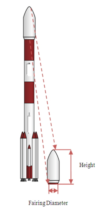
In this section, we discuss the initial design approach for maximum reduction of the footprint area before the mirror is launched into orbit. Various design approaches mentioned in the referenced literature have been studied for the deployment of six segments at a compact volume. In the launch vehicle, the payload fairing diameter is limited. However, the height of the launch vehicle fairing is longer than its diameter (Fig. 1). Keeping these constraints in mind, our goal is to design a mechanism that can move the segments axially along the length of the fairing and also fold the segments.
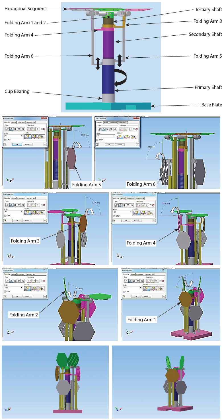
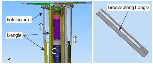
In this section, we discuss the folding mechanism and deployment strategy. Fig. 2 shows the working principle of the mechanism and the names of the components. The folding mechanism strategy involves the axial movement of the segmented mirror (i.e., bolt-nut, screw jack mechanism). In this mechanism, either the bolt (i.e., the primary shaft) is fixed or the nut is fixed (i.e., folding arms). Here we have designed fixed folding arms by using a slotted L-angle. The folding arms move axially upward when the primary shaft is rotated in a counterclockwise direction. When the folding arms move axially downward, the primary shaft rotates in a clockwise direction around the primary shaft axis. The two folding arms are fixed and mounted on the secondary shaft, and another two folding arms are fixed and mounted on the tertiary shaft.
5. DESIGN OF MECHANISM COMPONENTS
In this section, we discuss the design of the segments, the mechanism base plate, shafts, hinge arms, and cup bearing.
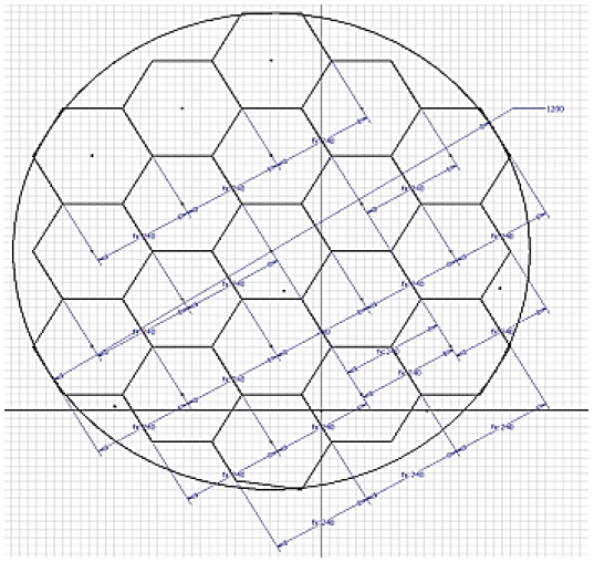
The shape of the segment was selected to be a hexagon owing to its optimum fill factor to form a circular aperture. An oval mirror, for example, would provide images that are elongated in one direction. A square mirror would send much of the light out of the central region. Hexagonal segments are naturally arrayed in rings, as shown in Fig. 3.
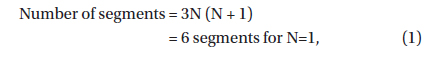
Expression (1) is the governing equation for the number of segments in an N-ringed segmented mirror (Srinivas & Arora 2013).

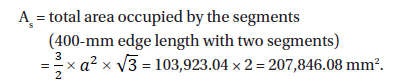
where N is the number of rings in a ringed segmented mirror. Hexagonal segments also tend to be easier to support against gravity and to attach to position of actuators (motor drive, one per segment) because of their symmetry. Overall, the advantages of hexagonal segments have made them the segmentation pattern of choice for most current and planned segmented-mirror telescopes (Ealey & Wellman 1991). The hexagonal shape allows for a segmented mirror with a high filling factor and six-fold symmetry. A high filling factor indicates that the segments fit together without gaps. If the segments were circular, there would be gaps between them. The fill factor is defined as the ratio of the maximum obtainable area of the segments, as follows (Srinivas & Arora 2013):

where
and

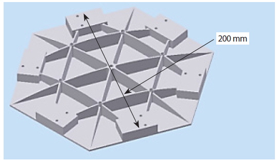
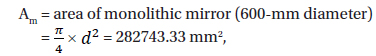
Hence, the fill factor of the segment = 73.51%. Fig. 4 shows the design of the proposed hexagonal segment. To demonstrate the mechanism, a prototype laboratory model of a 600-mm-diameter primary mirror was designed and fabricated.
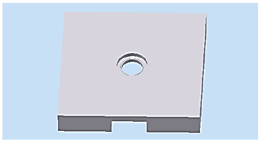
5.2 Design of Mechanism Base Plate
A base plate is designed to serve as a support structure for the entire mechanism and motor housing. The primary shaft is located on the base plate. The secondary shaft is located on the primary shaft, and the tertiary shaft is located on the secondary shaft, as shown in Fig. 2. Fig. 5 shows the design model of the base plate. The plate also forms a mounting space for the electric motor drive platform.
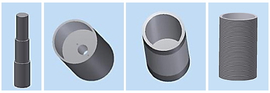
The shaft acts as a drive as well as a support for the folding arms (Fig. 6). The shafts are designed with external threads to drive the hinge arms. Since mass is a primary constraint in designing the mechanism, the shafts are hollow, which reduces overall mass and resists bending loads. The hollow space of shafts is utilized to accommodate the electric motor drives.
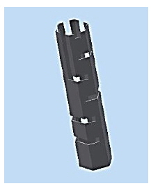
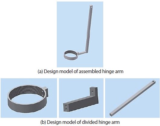
The hinge arms are designed to support the segments. The hinge arms move upward and downward axially during the deployment and folding of the mechanism. The heights of the hinge arms are chosen based on the requirements of folding height. Fig. 7(a) shows a hinge arm designed from a single block. Fig. 7(b) shows the hinge arm divided into three pieces, resulting in a reduction of material. Volume was reduced by 77.85% because the hinge arm was designed using three pieces rather than a single piece of material.
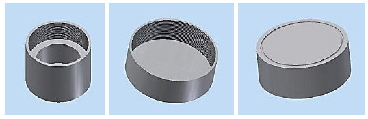
The purpose of a bearing is to reduce friction between two mated rotating parts. In the proposed design, a bearing is required to transfer the load to the mated part without transferring motion. Hence, aluminum cups are designed based on the diameters of the shafts. A groove of 1.2 mm is manufactured on the inner side of the driving cup and on the rear side of the driven cup. Spherical stainless-steel balls with a diameter of 3.14 mm are inserted in the grooves of the cups. The balls act as ball bearings (Fig. 8).
6. DESIGN CHALLENGES AND REDUCTION OF MASS
In the previous section, we had discussed the design of individual components. In this section, we describe the reduction of mass in structural parts. Supporting and fixing the folding arms at a predetermined position around the primary shaft was a challenge. Initially, as shown in Fig. 9, a hexagonal frame with grooves along its radial direction was designed to constrain the position of the folding arms. However, the frame was too bulky and heavy, and was expensive to manufacture. Hence, we decided to constrain the position of the folding arm by using an L-angle, shown in Fig. 10, with a groove along its longitudinal axis. When the primary shaft is rotated, the hinge arm is driven along the groove on the L-angle. Implementing the L-angle greatly reduced weight and material consumption.
In this section, we describe the materials used to realize the prototype version of the mechanism for demonstration. The design of the mechanism’s parts requires a consideration of system specifications and limitations, materials properties and processes, component design and analysis, and mechanism assembly and finishing (Peters & Leyens 2009). Several key material properties will be drivers for the selection of the mechanism material. A material may have a coefficient of thermal expansion (CTE). Thermal expansion and conductivity coefficients must all be matched to provide stable segment or make the mechanism possible. The mirror is developed from a single homogenous material. Weight is most effectively reduced by reducing density. As a rule of thumb, each kilogram of direct weight saved in a primary structure results in nearly another kilogram saved in a primary structure, which results in nearly still another kilogram saved indirectly in another part of the spacecraft. A space vehicle with a reduced takeoff weight affects the amount of fuel burned. There are enormous economic and ecological benefits associated with lightweight design (Jacobson et al. 1998).
The mass of the primary mirror always determines the mass of the telescope. Space-borne telescopes will gain benefits significantly from lower areal densities. The areal density is often limited by the stiffness-to-weight ratio of the primary mirror. Materials for primary mirrors deployed in space must have low density, low thermal expansion, high stiffness, and high thermal conductivity. The material for the mirror can be selected by comparing various mirror materials, as shown in Table 1. Considering strength, density, cost, and the manufacture of a prototype version for the laboratory, it is quite obvious that the aluminum 6061 T6 alloy (a classic lightweight aerospace alloy) is preferable. Table 2 shows the chemical composition of aluminum 6061 T6 alloy (Srinivas & Arora 2013). Table 1 shows the relative specific strength of several materials. Other factors may drive the selection of the material, including the need for cryogenic figuring owing to change from ambient to cryogenic temperatures. No single material will exhibit strong characteristics in all areas. A balance will be required in selecting the best material based on properties, cost, and ease of fabrication.
[Table 1.] Material Properties (Srinivas & Arora 2013).
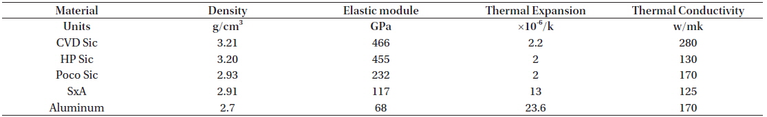
Material Properties (Srinivas & Arora 2013).
[Table 2.] Percentage of chemical composition of Aluminum 6061 (Srinivas & Arora 2013).

Percentage of chemical composition of Aluminum 6061 (Srinivas & Arora 2013).
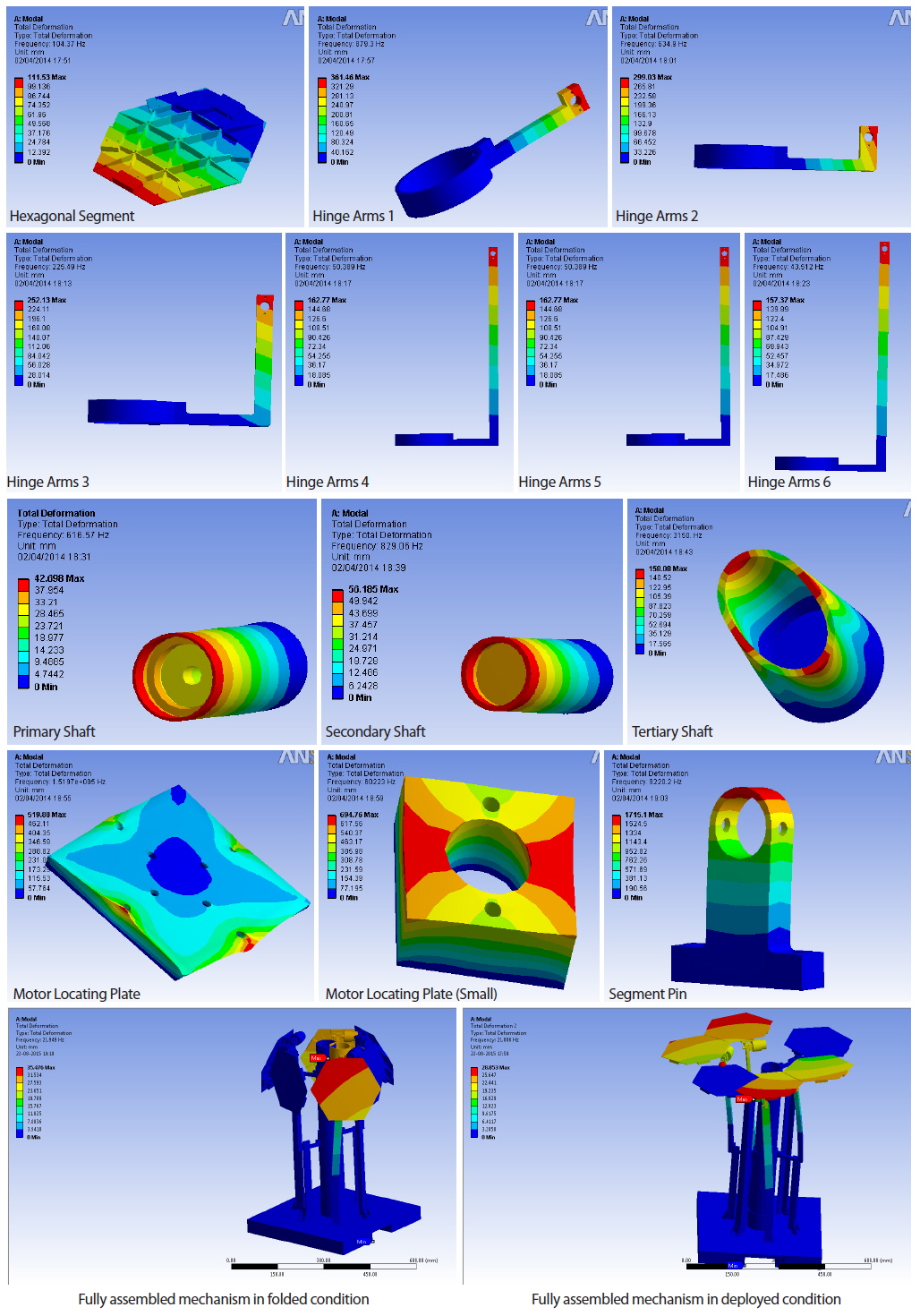
The main goal of the modal analysis is to find the natural frequency of the mechanism across a different number of modes. In order to illustrate our analysis, the mass is assumed to be distributed equally between the segments, 0.4 kg each and the damping will be assumed uniformly. Fig. 11 shows the modal analysis results for the individual components, fully assembled in folded and deployed conditions, for the first six global modes.
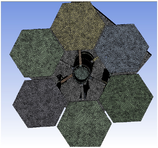
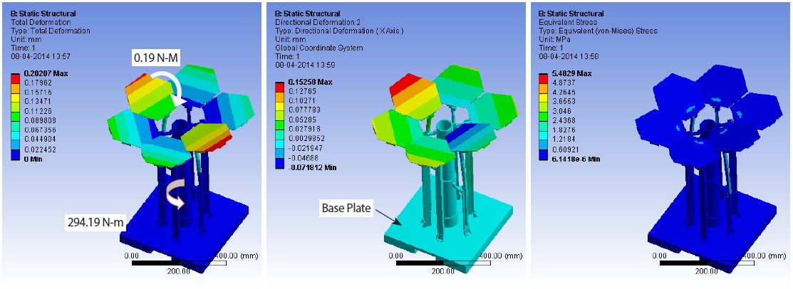
In this section, we describe the static structure analysis of the mechanism. The design and development of the foldable mechanism depends on structural analyses because the in-orbit behavior of the structure must be precisely predicted during the design (Jacobson et al. 1998). Fig. 12 depicts a typical finite element model (FEM) of the deployable mechanism. The first six modes are global modes. The FEM represents a segmented primary mirror with a 600-mm outer diameter. Each mirror segment is attached to a folding arm (reaction structure) with one actuator motor drive. A structural analysis determined that six axial support points keep the stress level on a 600-mm-diameter, 1.5-mm-thick primary mirror below a 294.19-Nm (external torque load) moment load acting on the primary shaft and a 0.19-Nm (external torque load) moment axial load acting on each segment. A tetrahedral mesh with an element length of 10 mm was used for the analysis. To design the foldable mechanism, we performed a total deformation; Fig. 13 shows the analysis results with directional deformation and von Mises stress. The load acting on the mechanism is a standard gravitational load along the z-axis, the motor torque is 0.19 Nm for each segment, and the maximum load affects folding arms 5 and 6 because these arms have greater heights than the other four folding arms. The base plate is a fixed support. The results of the maximum total deformation, maximum directional deformation, and von Mises stress are 0.2020 mm, 0.1525 mm, and 1.2184 MPa, respectively.
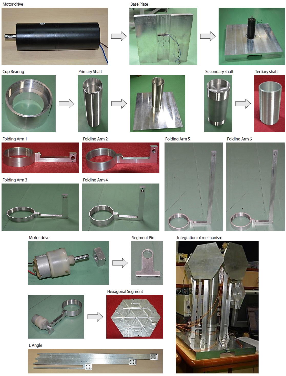
The design finalized from various simulations was fabricated to realize a working prototype of the mechanism. Various processes used for the fabrication of the components are described in this section.
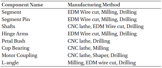
All of the designed components were converted into detailed dimensional drawings consisting of precision and tolerance details for each part. The parts were realized and assembled in order to demonstrate a working prototype of the proposed deployable mechanism. Table 3 lists the manufacturing processes involved in the fabrication of each component. Each component was manufactured by a precise method.
[Table 3.] Component fabrication by machining process.

Component fabrication by machining process.
10. REALIZATION AND INTEGRATION
Fig. 14 shows the fabricated parts and the electric drive used to drive the mechanism.
In this section, we describe the testing of the prototype mechanism and final validation of the mechanism by comparing the design and fabricated prototype.
11.1 Ground Testing and Validation by Testing Mechanism
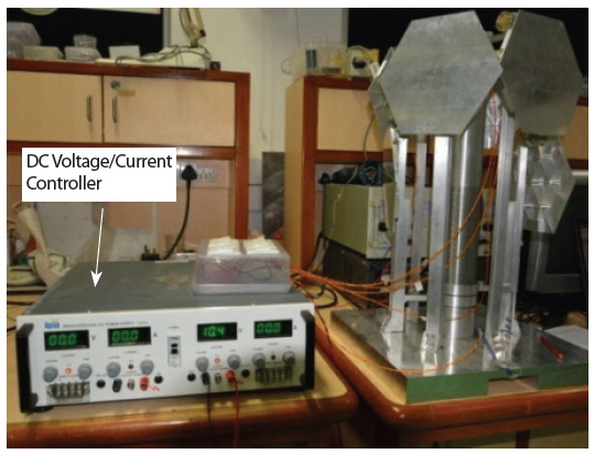
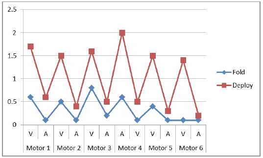
The realized assembly was subjected to multiple deployment and folding tests of the mechanism by number of repeatability test. The ground-test setup of the mechanism consists of a DC power controller (Fig. 15), DC motor drive, hexagonal segments, and drive segments pin. The test equipment can have additional effects on the test hardware and dynamic behavior of the deployment of segments. From examining Table 4 and Fig. 16, segments 1 and 2 require a lower DC voltage (V) and current (A) to operate the motor during folding because the segment moves in a downward direction and thus gravitational force assists with the deployment. However, when a segment deploys, it requires more voltage and current because it moves against the gravitational force.
[Table 4.] DC operating voltage and current for folding / deploying.
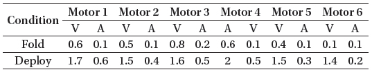
DC operating voltage and current for folding / deploying.
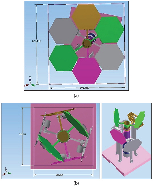
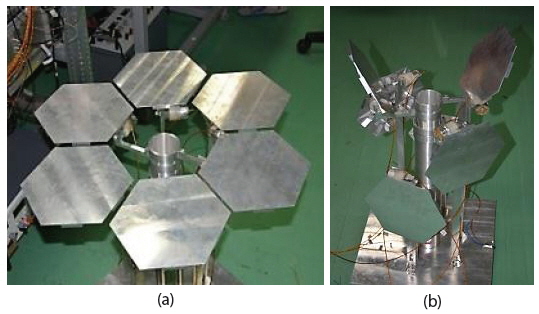
The mechanism is validated by comparing the footprint area of the designed model and the prototype model. Figs. 17(a) and 17(b) show the design models of the mechanism when fully deployed and fully folded, respectively. Figs. 18(a) and 18(b) shows the prototype mechanism in its fully deployed condition and fully folded condition, respectively.
After making these comparisons, we successfully validated the prototype laboratory model for a single stage of deployment, as well as the folding axial mechanism. The proposed mechanism to fold and deploy the segmented mirror exhibited an overall reduction in footprint of 65.62%. Eq. (3) describes the footprint area reduction:

where
Ad = Area of deployed segments = Length × Width = 590.21 × 620.11 = 366,001.76 mm2 Af = Area of folded segments = Length × Width = 360.31 × 349.21 = 125,828.43 mm2 = 65.62 %
A novel axial folding and deployment mechanism was designed and developed for a segmented mirror with a 600-mm aperture diameter to be used as a primary telescope mirror. The designed parts were realized using various manufacturing processes and were assembled to demonstrate a working prototype. Folding and deployment tests were carried out multiple times to ensure the repeatability of the mechanism. The value of the footprint reduction in the realized prototype is comparable with the designed value. The effectiveness of a unique design for an axial folding mechanism was proven by successful demonstration for a single stage of segment ring with a 65.62% footprint area reduction. This mechanism can be scaled up to the required size for large space mirrors. In the future, this concept can be utilized for large-aperture space telescopes that can fit into fairing space and can deploy once in orbit.