Several biometric features can be used in individual identity recognition, including fingerprint, iris, and face. Many of them are applied widely in modern society. As a biometric feature, finger vein patterns have attracted significant attention. Compared to other biometric features, finger veins offer the advantages of noncontact acquisition, liveness detection, internal features that are difficult to copy, alter
Two methods are used to acquire finger vein images, namely transmission-type and reflection-type acquisition. Studies have emphasized the transmission-type finger vein acquisition and recognition, because its images are of higher quality and are easily acquired, and this recognition system eventually yields better results compared to reflection-type recognition. Few studies have concentrated on reflection-type acquisition because of its relatively low image quality [9].
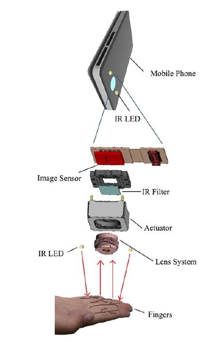
However, transmission-type acquisition devices are large and require a hole or groove into which the finger must be placed. Such a device is not suitable for integration into small, portable consumer devices. By contrast, reflection-type finger vein recognition systems have small acquisition devices that can be installed on a flat surface, so such a recognition system could be applied to small, portable consumer devices, such as smartphones, tablets, or in-home automation systems. Therefore, a reflection-type finger vein recognition system has the potential for mobile application.
Some studies on reflection-type vein recognition have been published over the past few years. However, they have concentrated on palm and palm dorsa veins, while only a few of them have focused on reflection-type finger vein recognition. Kato
In this study, smaller size results in poorer quality of finger vein images, and a lower recognition rate than that obtained by Kato
1) For mobile application, locating the region of interest (ROI) in a four-finger pattern is easier than for palm or palm dorsal patterns, since the direction of the fingers and the root of a finger can be used to locate the ROI. 2) Four fingers can provide more features for recognition than can a single finger. 3) The outline of four fingers can also be used to assist recognition.
In using four-finger vein images, a key point is ROI localization, for which Liu
For feature extraction, Mirmohamadsadeghi and Drygajlo [6] proposed a method based on local binary pattern (LBP) and local derivative pattern. Wu
Most research currently focus on palm vein and palmprint recognition, whereas limited research pays attention to four-finger vein recognition. This paper presents our experimental findings on reflection-type finger vein recognition.
In transmission-type finger-vein recognition, the camera and NIR reflection light-emitting diodes (NIR LEDs) are located on opposite sides of the fingers, as shown in Fig. 5(a). In reflection-type finger vein recognition, the camera and NIR LEDs are located on the same side of the fingers, as shown in Fig. 5(b). In addition, NIR light is projected onto the finger surface, and a part of the light is reflected by the finger. Some light is absorbed by the hematocrystallin in veins while and some is scattered in the fingers, which breaks the light into two parts, that is, one part comings through the fingers, and the other projecting back to the finger surface and finally projecting into the camera. Therefore, on the side with the NIR-sensitive camera, the vein region is darker than the non-vein region.
A database is needed to test the algorithm. However, no such database exists at present [9] because fingers have not been used in reflection-type vein recognition. Thus we construct a database of four-finger vein images with a self-made acquisition device, mainly consisting of a light source and a camera. The light source is a high-power IR LED (1 W, Tyntek Corporation, Taiwan) of peak wavelength 850 nm and range 800-900 nm. The infrared camera (ODSX, type H14) has an imaging angle of 130° and image acquisition time of 33.3 ms.
The database contains 592 images of 74 hands from 37 individuals. Among these subjects, 24 are males and 13 are females, with ages ranging from 20 to 25. The subjects are primarily undergraduate students and faculty members of Shandong University. Given that every hand bears different personal information, the two hands of a person can be considered as two identities. More details can be found in [9].
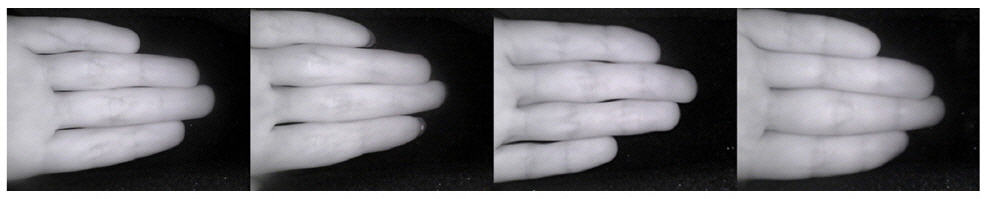
The database consists of four-finger images presenting the four fingers of a palm, without the thumb. On the surface of the acquisition device is a guide, a frame in the shape of a hand, to help users place their fingers correctly. The fingers should be close together and occupy most of the area of the image, and the images must include finger tips and roots and avoid any shelter. If a user does not close his or her fingers or position them properly, the preprocessing stage may fail. During the image-capturing stage, the fingers are put on a uniform black background to simplify preprocessing. Examples of four-finger vein images in the database are shown in Fig. 6. The processing of finger-vein images with complicated backgrounds is the next goal of our research.
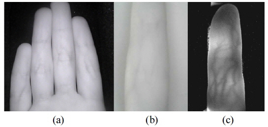
In transmission-type finger vein recognition, researchers adopt one-finger images, because the images are of high quality and are rich in finger vein information, as shown in Fig. 7(c). These features are crucial to personal identification. However, as mentioned, a reflection-type finger vein image has lower quality than a transmission-type image, and a one-finger image does not contain enough finger vein information for personal identification, as shown in Fig. 7(b). When more fingers are used, the finger vein information is richer than for one-finger images. Stretching out two or three fingers on the acquisition device is uncomfortable for the user, and may lead to improper gestures that make preprocessing difficult. Therefore, for convenience and performance in reflection-type finger vein recognition, four-finger images are adopted in the proposed method, as illustrated in Fig. 7(a).
The directory structure of the database indicates information about the subject. The name of each image also shows personal information, including individual identifier, gender, and left or right hand. The resolution of each image in the database is 640×380, in PNG format.
In finger vein images, due to nonuniform illumination caused by diffuse reflection, some useless data and noise exist in the background, influencing the final recognition result. A simple but effective method to cope with problems of specular reflection in reflection-type finger vein recognition can also be used in this application [25]. This method is provided by the iterated conditional modes algorithm, followed by the maximum
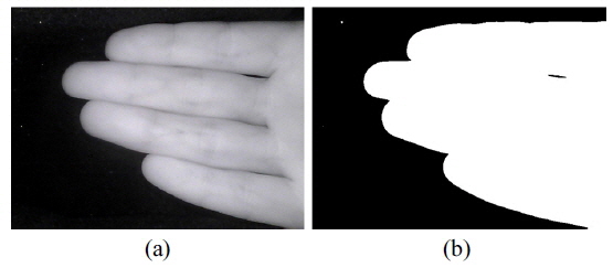
As mentioned above, noise is present in the images due to diffuse reflection in the background. To remove these influences, image binarization is used. Otsu’s method [10] is used to determine the threshold value for image binarization automatically, to minimize the interclass variance of the thresholded black and white pixels. In recognition systems this method is more accurate and convenient than others [11-13] (shown in Fig. 8).
However, some unwanted noise remains in the resulting binary image, due to abnormally bright dots in the background, as shown in Fig. 8(b). Considering that the scale of noise is smaller than the finger region, we can remove the noisy regions according to size. The number of nonzero pixels is smaller than the predefined threshold. Because the size of a noisy region is usually smaller than 100 pixels, the threshold is empirically set to 100. To find the connected regions, we refer to the work of Haralock [14].
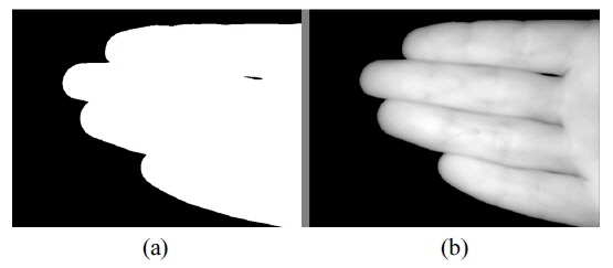
After this procedure, the final binary images are acquired, as shown in Fig. 9(a).
A finger vein image with background removed is obtained by multiplying the original image by the binary image. The resulting image is illustrated in Fig. 9(b).
Although images were captured with constraints during acquisition, the fingers in the images are at different angles. Their direction must be adjusted to ensure accurate ROI localization and recognition by estimating the principal direction of fingers in the images. In a four-finger image, three gaps exist between the four fingers. The three gaps are approximately parallel, and their direction is defined as the principal direction of the fingers. The orientations of the fingers in each image of the same user are roughly the same and approximately horizontal. However, a small angle always exists between the gaps and the horizontal direction. Direction adjustment aims to determine that angle and use it to adjust the gaps to be horizontal.
To acquire the angle between the gaps and the horizon, a computing window that includes the finger gaps is defined: The region determined by the middle 1/3 in width and the middle 3/5 in height of the image, which contains a large part of the finger gaps, is regarded as the computing window. Sobel horizontal and vertical templates [15] are used to convolve the image and acquire the horizontal gradient component
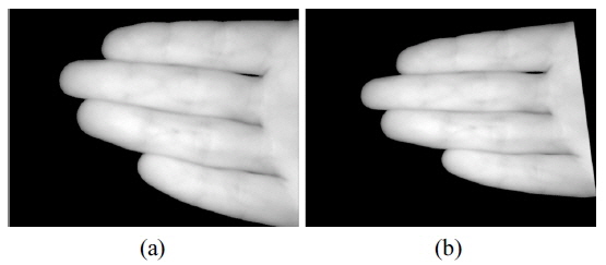
Finally, we use affine transformation to complete image rotation with the obtained angle. The images before and after direction adjustment are shown in Fig. 10.
3.3. Localization of Key Points
In the proposed method, to locate the finger vein ROI the finger roots must first be found. The modified Harris corner-detection algorithm is adopted to locate the finger roots. The theory of modified Harris corner detection is introduced below.
A corner is a point that changes significantly in both horizontal and vertical directions, that is, both
The algorithm flow is as follows:
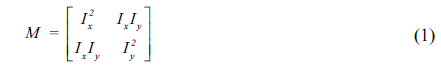
1) Every pixel is filtered with horizontal and vertical gradient operators. Ix and Iy are obtained. The following equation is computed:
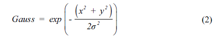
2) The four elements of matrix M are filtered with a Gaussian smooth filter, and a new M is obtained. A discrete Gaussian function with zero mean value in two dimensions is expressed as follows:

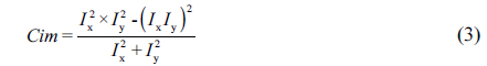
3) M is used to compute the corner value matrix Cim according to the following equation:

4) In matrix Cim, the points with value both larger than a threshold and the local maximum in a neighborhood are considered to be corners. The neighborhood is defined as a 16×16 region centered around the corner.
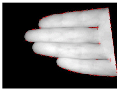
Increasing the threshold value decreases the number of extracted corners, whereas decreasing the threshold value can increase the number of extracted corners. The size of the neighborhood used in computing the local maximum also influences the number of extracted corners, and the tolerance of the algorithm. The local maximum can be acquired by comparing dilated and original images. The corners detected by this method are marked with red crosses in Fig. 11.
As shown in Fig. 11, finger roots are found along with many false corners. The three key points are the three finger roots between each pair of two fingers. Most of the false corners must be eliminated to locate the key points accurately.
Most of the false corners are located on the border of the hand. Locating the edge of the palm can help to eliminate the false corners nearby. The Canny operator is adopted to extract the hand’s edge, which is further reduced to the width of a single pixel. The distances between the false corners and the palm edge are computed, and then the false corners near the boundary are removed accordingly.
Only the corners between fingers and in other irregular positions remain. The corners in these positions are relatively difficult to remove. However, finger roots have specific features; for example, the grayscale values of the regions on each horizontal side of the finger root differ significantly. Accordingly, the corners are removed when the grayscale values of the regions on each horizontal side of the corner have only small differences. Eventually the remaining two or three key points are used to locate the ROI.
In conclusion, the algorithm for key-point localization can be described as the following steps:
1) Detect the corners using the modified Harris corner-detection algorithm. 2) Locating the palm boundary by edge detection based on the Canny operator, then remove the corners detected in Step 1 that are near the palm boundary. 3) Compute the grayscale-value differences V between the left block and right block of each corner, and remove each corner with small V. The remaining corners are regarded as the finger roots.
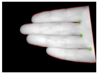
The results of key-point localization are shown in Fig. 12, where the green circles represent the locations of the key points.
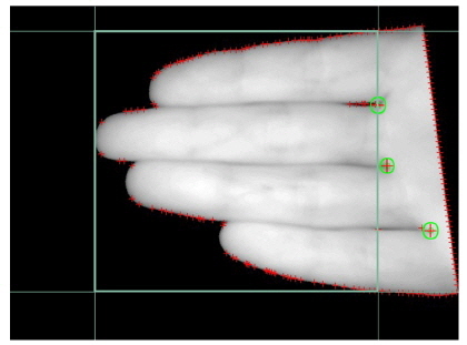
A rectangular coordinate system is built on the finger vein image. The pixel in the leftbottom corner is considered the origin, and the horizontal and vertical directions are denoted as
The idea of normalization is to utilize the invariant moment of an image to find a set of parameters to eliminate the influences of other transformation functions in image transformation. In other words, normalization involves converting the original image to the corresponding unique standard form that is invariant to the translation, rotation, and scale of the image.
Moment-based normalization generally has four components, namely coordinate centralization, x-shearing normalization, rotation normalization, and scale normalization. In this application, although the ROI is obtained, in general the size of the ROI differs for each image. To increase recognition accuracy, the ROI should be normalized in both rotation and scale. In Subsection 3.2, rotation normalization was already conducted. As to scale normalization, according to the average size of a four-finger region from the images in our database, the ROI is normalized to a fixed size of 350×300 by affine transformation.
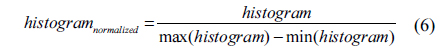
In addition to moment-based normalization, gray-level normalization is needed to increase the accuracy of a recognition system, by avoiding the influences caused by an imbalanced grayscale distribution. Gray-level normalization is achieved by applying the following equation to every pixel of the ROI:

where
IV. FINGER VEIN FEATURE EXTRACTION
Finger vein feature extraction is another crucial part of our recognition system, and directly influences the final recognition accuracy. The selection and optimization of features are important, although finding the most significant feature is always difficult. As a key problem of pattern recognition, testing the selection of features requires considerable work. In our scheme, we adopt a method that combines a Gabor filter bank and LBP coding.
The Gabor transform, proposed by D. Gabor in 1946 [16], has many advantages and is suitable for pattern recognition. The Gabor function is similar to the visual stimulation response of ocular cells in the human visual system. This function has some good properties in extracting information about the local spatial and frequency domains of a target. The Gabor function is also sensitive to the edges in an image, and can provide good direction and scale selection features. Moreover, this function is insensitive to light variance. With these properties, it is widely used in the analysis of visual information. The Gabor filter can be used to extract relevant features in different scales and directions.
The two-dimensional (2D) Gabor filter can be used in image analysis. This filter is often used to describe and represent texture information. The real and imaginary parts of the 2D Gabor function are respectively called the even and odd Gabor functions. Our application aims to enhance the vein features in fingers, so we adopt the even Gabor function as our filter function.
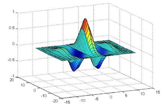
The spatial Gabor filter with even symmetry is defined by the following equation:
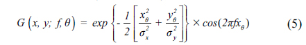
where
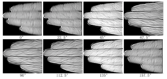
A bank of even-symmetry Gabor filters is adopted. The total number of filters is eight, corresponding to the eight cardinal and ordinal directions: 0°, 22.5°, 45°, 67.5°, 90°, 112.5°, 135°, and 157.5°. These are used to filter the ROI of the vein image in eight directions, yielding eight images with the local features of the vein, as illustrated in Fig. 15. The vein’s features are more salient after filtering. Yang
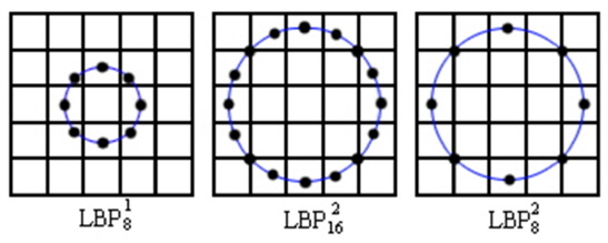
LBP is an operator that describes the local texture feature of an image and processes rotation and gray-level invariance. First proposed by Ojala
In this scheme, we use an eight-neighbor circular LBP operator to extract the feature vectors of the eight filtered images, and then merge the eight feature vectors into one vector to represent the original image. The vector obtained is used in final matching.
The steps to extract the reflection-type finger-vein feature vector are as follows:
1) The original image is expanded by one pixel. The expanded pixels are filled with the values of the border pixels. The ROI of 350×300 pixels is divided into 6×16 cells of size 58×19 pixels, without overlap. 2) For each pixel of every cell, the grayscale value is compared to those of the eight adjacent pixels. If the grayscale value of the adjacent pixel is larger, the pixel is set to 1; otherwise, the pixel is set to 0. Thus, by comparing eight neighbors, an eight-bit binary number is generated, that is, the LBP value of the center pixel. 3) The histogram of every cell, which is the frequency of occurrence of each number, is computed. The histograms are then normalized according to the following equation:
4) Finally, the statistical histogram of each cell is combined into a feature vector, that is, the LBP feature vector of the filtered image. 5) Steps 1 to 4 are repeated until all eight feature vectors of the eight filtered images are obtained. The eight feature vectors are then combined end to end into one vector in the same order, denoted as [v0°, v22.5°, v157.5°]. The vector so generated is the feature vector of the ROI of the original image, which can be used in the matching stage.
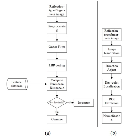
The flow chart for the proposed algorithm is presented in Fig. 17(a), while the flow chart for the preprocessing stage is shown in Fig. 17(b).
As described in Section II, our constructed database contains 592 images of 74 hands from 37 individuals. Each hand has eight images. Among these subjects, 24 are males and 13 are females, with ages ranging from 20 to 25. Given that every hand carries different personal information, the two hands of a person can be treated as two identities. A hand is considered as a class; thus a total of 74 classes are obtained. Each class contains eight samples during experiments. In the experiments, all samples in the database were divided into two parts, namely the training and testing sets. Each set has 74 classes, and each class has several samples. The training set has 74 classes, and the training set of a class consists of two to six images, which are randomly selected from images in the class. The testing set also has 74 classes, each class containing the remaining samples of the corresponding class.
In this paper an automatic ROI detection method for a four-finger image is proposed, and to evaluate the effectiveness of the method a set of experiments was conducted. The 592 images were all detected via the proposed method, and the number of images was computed with respect to the number of detected finger roots in one image. The experimental results are shown in Table 1. If the number of detected finger roots is 0 or beyond 3 (a four-finger image contains 3 finger roots at most), the ROI detection is sure to fail. Then the number of correctly detected images and the accuracy were calculated as 583 and 98.5% respectively.
[TABLE 1.] Evaluation of ROI detection method
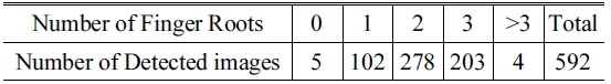
Evaluation of ROI detection method
The matching strategy involves computing the Hamming distance between one sample in the testing set and every sample in the training set. The class in which the Hamming distance between the training sample of that particular class and the testing sample is the shortest is regarded as the class of the testing sample. If that class is the same as the class to which the testing sample belongs, then the result of identification is true; otherwise, the result of identification is false. When all of the testing samples have been identified, the accuracy of the proposed method can be computed. When the size of each class in the training set is 3, the recognition rate is approximately 92.4%. The recognition rate changes significantly with the size of each class in the training set; the trend is shown in Table 2. To emphasize the effectiveness of the proposed method, the results were compared to those using Yang’s method [17] and Lee’s method respectively. When computing the accuracy of the methods of Yang and Lee, only their feature-extraction algorithms were adopted, and the ROI detection method and matching strategy were taken from the proposed method. The experiments show that the proposed method outperforms the other two.
[TABLE 2.] Recognition rate changes with the size of each class of the training set
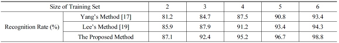
Recognition rate changes with the size of each class of the training set
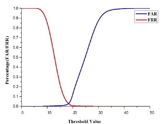
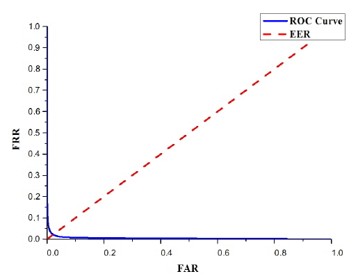
False acceptance rate (FAR) and false rejection rate (FRR) are the most important parameters indicating the performance of a recognition system. FAR refers to the number of illegal persons who have accessed the system over the total number of illegal persons attempting to use the system. FRR refers to the number of legal persons who are denied access to the system over the total number of legal persons who attempt to access the system. The trends for FAR and FRR as the threshold increases are presented in Fig. 18. FAR and FRR change with threshold.As the threshold increases, FAR and FRR respectively increase and decrease, in the same coordinate system, the receiver operating characteristic curve (ROC curve) is obtained. The ROC curve for the proposed method, when the size of the training set is 3, is shown in Fig. 19. According to the ROC curve, the equal error rate of the proposed method is 2.14%.
The recognition performances for the four-finger vein pattern, palm, and palm dorsal patterns are compared in verification mode, which are as follows:
From Table 3, it can be seen that the four-finger vein pattern can achieve EER=2.14. Although the performance of recognition by four-finger vein pattern does not outperform those for palmprint and palm-vein pattern, the accuracy of the proposed pattern can meet the needs of mobile applications.
[TABLE 3.] List of relative biometrics and their performances in verification mode
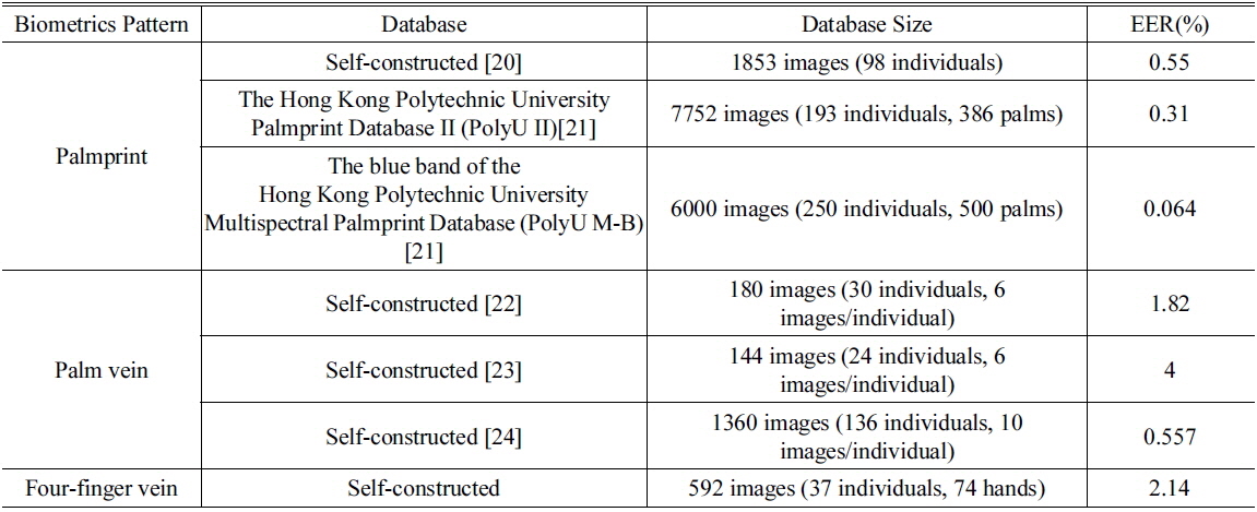
List of relative biometrics and their performances in verification mode
Previous studies have focused on transmission-type finger vein recognition, or reflection-type recognition that uses palm or palm dorsa rather than the finger region, and are therefore not suitable for mobile consumer device application. In this paper, reflection-type finger vein recognition that can be used in mobile consumer electronics was proposed. Based on a reflection-type finger vein image database, the proposed method achieved a recognition rate of 97.3% when six images are in the training set. Although the recognition rate is not better than that for transmission-type recognition, the proposed reflection-type finger vein recognition can be used for personal identification and it is suitable for mobile consumer applications, which cannot be implemented by a transmission-type method.

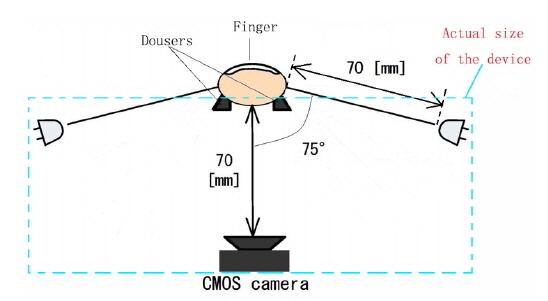
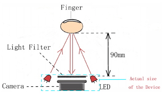
![Structure of the reflection-type acquisition device designed by Kato et al. [2].](http://oak.go.kr/repository/journal/15934/E1OSAB_2015_v19n5_467_f001.jpg)

![(a) Transmission-type finger vein acquisition and (b) reflection-type finger-vein acquisition [9].](http://oak.go.kr/repository/journal/15934/E1OSAB_2015_v19n5_467_f005.jpg)