In modern optical instruments such as mobile and black box cameras, plastic materials are widely used. The merits of plastic material include its being light, cheap, and easy to mold into aspherical surfaces. Because of its inherent temperature sensitivity, however, variation in ambient temperature significantly induces changes in refractive index, curvature of the lens, and thickness rather than glass. Since the thermal defocusing caused by such changes degrades image quality, a lens system using plastics should be designed to have stable performance over a specified temperature range.
defocusings, which are mainly induced by the large variations of refractive index with temperature and wavelength. In the infrared waveband, many design methods to reduce these defocusings have been reported [1-3]. However, these methods have difficulties in finding proper combinations of materials and lens powers.
As an alternative approach to overcome these problems, a graphical method has been developed [4-7]. Although this method is robust, it requires a complex process and calculations to achieve an athermalized and achromatized system having more than three elements. To solve these difficulties, another graphical selection method for optical materials, using an athermal glass map and equivalent single lens, has been developed [8]. This method is useful for finding proper combinations of materials for an athermal and achromatic system with multiple-lenses in contact. Because it does not take into account the lens spacing and housing, however, approximate solutions are obtained.
To consider the lens spacing and housing, in this paper we quantify the lens power, chromatic power, and thermal power by weighting the ratio of the paraxial ray height at each lens to them. In addition, we introduce the equivalent single lens and the expanded athermal glass map including a housing material [6-8]. Even though a lens system is composed of many elements, we can simply identify a pair of materials that satisfies the athermal and achromatic conditions by selecting the corresponding materials from an expanded athermal glass map.
By applying this method to design a black box camera lens composed of one glass and four plastic elements, a good solution having small chromatic and thermal defocusings is obtained.
II. ATHERMAL AND ACHROMATIC CONDITIONS
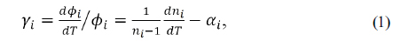
For a single thin lens of power


where
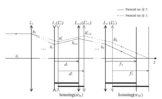
Figure 1 illustrates an optical system composed of
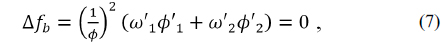
In such an optical system with an arbitrary number of elements, the following equations must be satisfied for axial color to be corrected [5-11]:


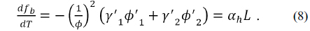
The thermal defocusing can be expressed as the difference between the thermal expansion of the housing and the change in back focal length (Δ

where
The athermal and achromatic conditions for a doublet are given by


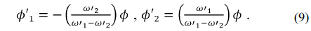
For a doublet to be achromatic, each element must have the power given in Eq. (9) by solving the Eqs. (6) and (7), as follows:
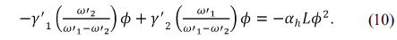
Inserting Eq. (9) into Eq. (8) results in an expression for the athermal and achromatic conditions for a doublet:

Assuming that the flange back distance is approximately equal to the back focal length, i.e. , then the athermal and achromatic conditions given by Eq. (10) are rewritten as follows:

III. EXPANDED ATHERMAL GLASS MAP AND EQUIVALENT SINGLE LENS
3.1. Expanded Athermal Glass Map
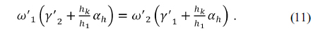
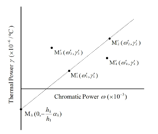
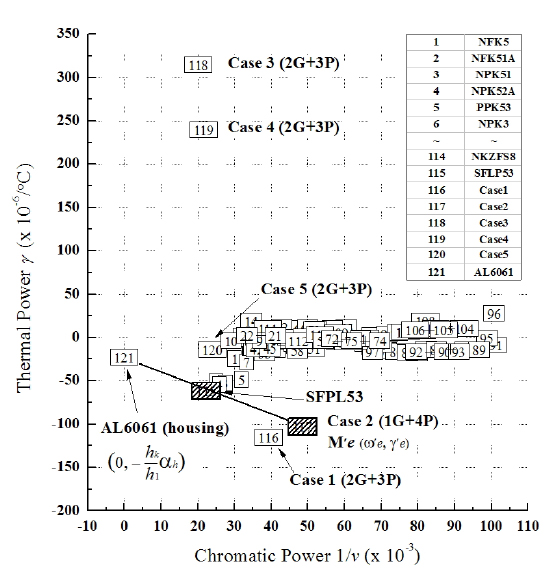
Figure 2 shows the expanded athermal glass map that plots chromatic power on the horizontal axis and thermal power on the vertical axis for a housing material; these powers are weighted by the relative paraxial ray heights. From the athermal glass map and Eq. (11), we can visually identify two materials that satisfy the athermal and achromatic conditions.
In an expanded athermal glass map, if two materials of
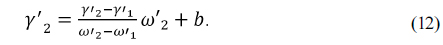
Then, rearranging Eq. (12) to solve for
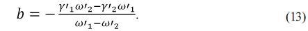
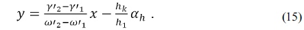
Next, rearranging Eq. (11) results in an expression for , as follows:
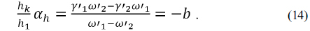
From Eqs. (12) to (14), we see that the line

From Eq. (15) we see how simple and intuitive it is to include the housing material. When two materials are given, unlike some of the previous methods [5-8], the proposed method can be used to visually determine exactly what CTE of the housing is required to athermalize and achromatize a system. Meanwhile, if any material
An athermal and achromatic doublet can be simply obtained from Eq. (11), but a very complicate process is required to have a lens system with many elements be athermal and achromatic simultaneously [4-7]. In this study, a lens system with many elements is substituted by an equivalent single lens that has the equivalent power, equivalent chromatic power, and equivalent thermal power. This equivalent single lens is useful in selecting a pair of glasses on the athermal glass map, like a doublet [8].
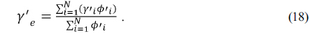
To consider the spacings between lenses, the equivalent lens power

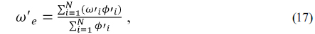

Although this is a multilens system, from Eqs. (17) and (18), its chromatic and thermal powers can be obtained simply. Thus, this equivalent single lens reduces the problem to that of a two-element system as a doublet. Consequently, a pair of materials that satisfies Eq. (11) can graphically be selected to simultaneously achromatize and athermalize an imaging lens. Unlike previous methods using a complex process [5-7], we can use this method to visually determine exactly what materials and housing are required to achromatize and athermalize a multilens system.
4.1. Analysis of a Starting Lens
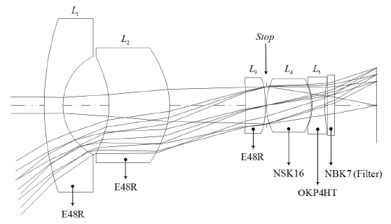
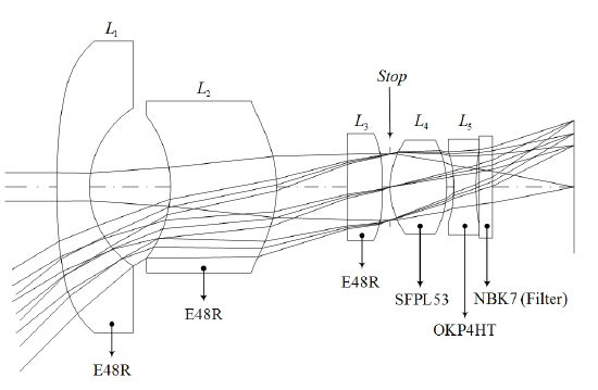
A black box camera lens composed of two glasses and three plastics (2G+3P), equipped with a 1/4-inch image sensor having a pixel width of 2 μm, is given as a starting point, as shown in Fig. 3 [12]. This patented lens has an

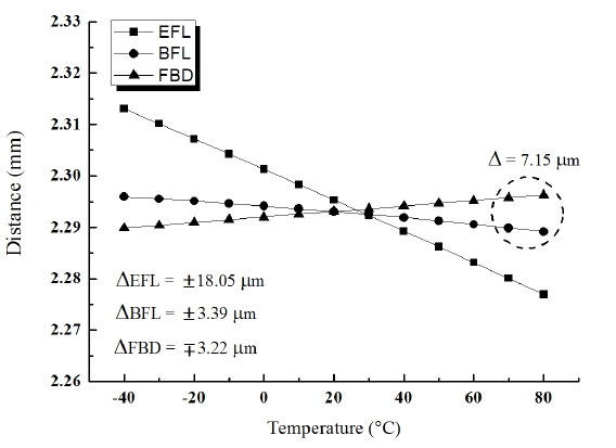
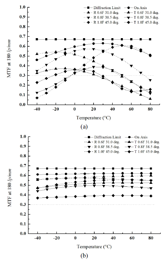
This lens has small variations in back focal length (ΔBFL) and flange back distance (ΔFBD) from −40℃ to 80℃: ΔBFL = ±3.39 μm and ΔFBD = ∓3.22 μm, as shown in Fig. 4. The change in effective focal length, ΔEFL = ±18.05 μm, is greater than the depth of focus. Note that the signs of ΔBFL and ΔEFL are opposite that of ΔFBD, which induces additional thermal defocusing at extreme temperature. The modulation transfer function (MTF) is unstable at both extreme temperatures, as shown in Fig. 9(a).
This patented lens partially fulfills the requirements of a black box camera over the specified temperature range; however, it consists of two expensive glasses. Because the plastic material has advantages over glass in cost and aspheric molding, in this research we replace the front glass (NSK16) with plastic (E48R) having similar index and Abbe number. Consequently, this lens has the configuration of one glass (
4.2. Graphical Selection of a Material Pair and Optimized Design
Figure 6 shows the expanded athermal glass map plotted for visible Schott and Ohara glasses, including housing material AL6061 (
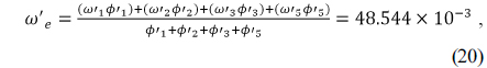
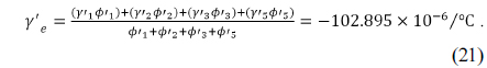
The equivalent single lens having and given in Eqs. (20) and (21) is located at in Fig. 6. By connecting this point to the y-intercept of with a line, the material of the fourth element
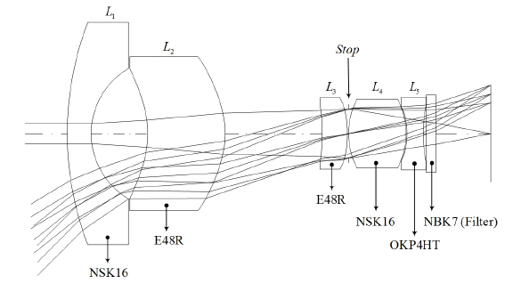
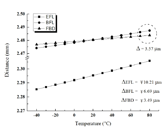
After replacing the fourth element’s glass with SFPL53, the temporary lens has been re-optimized using Code-V. Finally, a black box camera lens having good performance is obtained, as shown in Fig. 7. The thermal shifts of this lens are significantly reduced, as illustrated in Fig. 8. The variations of effective focal length, back focal length, and flange back distant over −40℃ to 80℃ are ΔEFL = ∓10.21 μm, ΔBFL = ∓6.69 μm, and ΔFBD = ∓3.49 μm respectively. Note that here the signs of ΔBFL and ΔEFL are the same as that of ΔFBD, which reduces the thermal defocusings over the whole range of temperatures. Thus, all thermal shifts due to temperature are less than the depth of focus. The chromatic focal shift between C- and F-lines is reduced to 1.45 μm, less than the 5.83 μm of the starting patented lens. In conclusion, the designed lens is achromatic in visible light and passively athermalized over the range −40℃ to 80℃.
Figure 9 shows the modulation transfer functions (MTFs) of two lenses with temperature. The MTF of the lens designed from athermal and achromatic process, even though its front element has been replaced with plastic, is much more stable than that of the starting patented lens over the specified temperature range. Also, the MTF at maximum frequency of 180 lp/mm is greater than 36% over all fields. The final lens design for a black box camera has an
To realize an achromatic and athermal multilens system, the lens spacing and housing have been taken into account in plotting an expanded athermal glass map. By graphically selecting the corresponding materials from an expanded athermal glass map, we can simply identify a pair of optical and housing materials that satisfies the athermal and achromatic conditions. By utilizing this method to design a black box camera lens with five elements, a good solution having small chromatic and thermal defocusings has been found. The chromatic focal shift is 1.45 μm between C- and F-lines, and the thermal defocusings over −40℃ to 80℃ are found to be less than the depth of focus. This lens is consequently achromatized and passively athermalized. In conclusion, this graphical method for selecting materials is expected to serve as a simple and powerful way to find design solutions.