검색 전체 메뉴
PDF
맨 위로
OA 학술지
Neighboring Elemental Image Exemplar Based Inpainting for Computational Integral Imaging Reconstruction with Partial Occlusion
  • 비영리 CC BY-NC
  • 비영리 CC BY-NC
ABSTRACT
Neighboring Elemental Image Exemplar Based Inpainting for Computational Integral Imaging Reconstruction with Partial Occlusion
KEYWORD
Integral imaging , Image inpainting , Bimodal segmentation , Occlusion removal , 3-D visualization
  • I. INTRODUCTION

    One of the advantages of the computational integral imaging (CII) is the capability of applying digital manipulation on the picked-up elemental images. Due to the digital manipulation, it is possible to reconstruct the 3-D image at a reconstruction plane of any desired depth. Furthermore, the recorded elemental images can be digitally post-processed.

    This property enables the CII to reconstruct partially occluded 3-D objects for 3-D visualization and recognition [1-19]. Several occlusion removal methods have been studied in [15-19] to solve the problem of the degraded resolution of the computationally reconstructed 3-D image, which occurs due to the partial occlusion. In these studies, the occlusion region is detected by calculating the depth map. Then, the region corresponding to the depth map with relatively small depth values is regarded as the occluding region, and is removed by occlusion removal methods. However, even though the occluding object is removed, there remain data missing holes which prevent us from getting better visual qualities of the reconstructed images. Therefore, in [20], a linear inpainting based computational integral image reconstruction (LI-CIIR) method has been proposed, which fills in the data missing region caused by the occluding object by the linear inpainting technique [21] using the information of neighboring pixels.

    It is shown experimentally in [20] that the LI-CIIR shows good results for images with objects having smooth surfaces. However, for the case that the object has a textured surface, the LI-CIIR cannot recover the textured data in the data missing region well. Furthermore, the LI-CIIR does not fully utilize the property that the same object region appears in several neighboring integral images.

    Therefore, in this paper, we propose a neighboring elemental image exemplar based inpainting (NEI-exemplar inpainting) method which utilizes the original exemplar based inpainting method [22]. The exemplar based inpainting technique suits well the integral imaging application, since the source for the exemplar based inpainting can be found not only in the elemental image of interest but also in neighboring elemental images. By using neighboring exemplars, the textures can be recovered in the data missing region.

    In addition, we also propose an automatic occluding region extraction method which can automatically segment the occluding region based on the use of the mutual constraint using depth estimation (MC-DE) [23] and the level set based bimodal segmentation [24]. The MC-DE performs a stable calculation of the depth map based on the mutual constraint that exists between neighboring elemental images. The level set bimodal segmentation automatically segments the object and the background regions based on the competition between the depth values obtained by the MC-DE. Experimental results show the validity of the proposed system. The quality of the 3-D image reconstructed from the elemental image array with the occlusion removed by the proposed method is almost identical to that reconstructed from the elemental image array without occlusion.

    II. PROPOSED METHOD

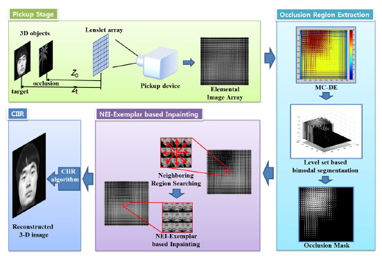
    Figure 1 shows the overall diagram of the proposed system. First, the partially occluded 3-D object is picked up and recorded through a lenslet array to form the digital elemental image array. Then, the occluding region is segmented out by the mutual constraint using depth estimation (MC-DE) and the level set based bimodal segmentation. After that, we apply the proposed neighboring elemental image exemplar based inpainting (NEI-exemplar inpainting) to fill in the missing data inside the occluding region. Finally, the 3-D image is reconstructed using the CIIR. We explain the details of each step in the next sub-sections.

       2.1. Occluding Region Segmentation

    One of the major problems in occlusion artifact removal is the automatic extraction of the occluding region. Recently, several methods have been proposed for the extraction of the occluding region. One of the most successful methods is that which computes the depth map based on the mutual constraints between the elemental images [23]. Hereafter, we call this method the mutual constraint using depth estimation (MC-DE).

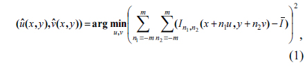
    In the MC-DE method, it is assumed that the translation of the same object is constant between neighboring elemental images. Using the constraint between (2m+1)×(2m+1) neighboring elemental images, the problem of finding the disparity vector (u, v) can be formulated as follows [23]:

    image

    where In1,n2 denotes the (n1, n2) -th elemental image, is the average all the intensity values In1,n2 for n1,n2 = -m ~ m and denotes the solution disparity vector at (x, y), where (x, y) is the position of the pixel under consideration. The disparity vector is computed for every pixel to form a disparity map.

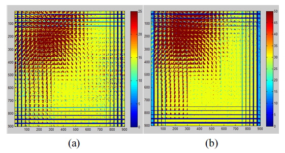
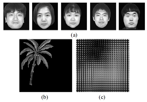
    Figure 2 (a) and (b) show the and components of the disparity vector obtained by applying (1) on the elemental image obtained by the optical settings shown in the pickup-stage of Fig. 1. The elemental image is composed of two objects (‘tree’ and ‘face’ objects) with different depths. It can be seen in Fig. 2 that the depth values of the ‘tree’ region and the ‘face’ region are well obtained by the MC-DE method.

    Applying a thresholding process on the figures in Fig. 2 with a suitable threshold value can discriminate the occluding region from the object region. However, it is not clear which threshold value discriminates the two regions well. Therefore, in this paper, we propose to utilize the level set based bimodal segmentation method. This method has been proposed by us in [24] to automatically segment target regions without using a pre-defined threshold value. The bimodal segmentation performs a two-phase segmentation based on the competition between the brightness values in the image.

    The level set based bimodal segmentation performs a two level segmentation by minimizing the following energy functional with respect to the level set function
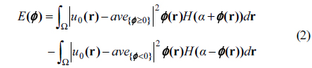
 φ:

    image

    Here, u0 denotes the brightness value of the pixel, r denotes the position vector of the pixel, ave{φ ≥0} and ave{φ <0} denote the average brightness values in the regions in u0 corresponding to the regions {r│φ (r)≥0} and {r│φ (r)<0}, respectively, and α is an arbitrary positive value. H(·) is the Heaviside step function defined as follows:

    image

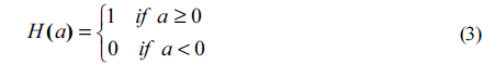
    For the problem of segmenting the object region based on the depth map, we set u0 as the depth map instead of a normal image. That is, we let

    image

    where and are the components of the disparity vector calculated by (1), and r = (x, y).

    The level set value at the r, i.e., φ (r) converges to α or depending on the value of u0.

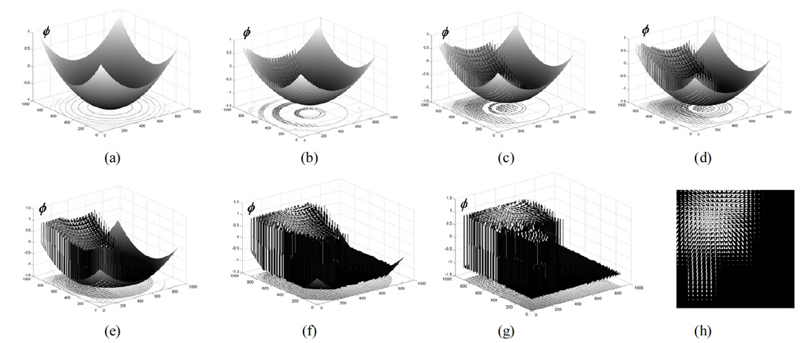
    Figure 3 shows the application of the level set bimodal segmentation on the depth map u0 where we set α = 1.

    It can be seen in Fig. 3 that the level set function automatically converges to the state of 1 or -1, since α = 1. That is, the level set function value converges to a positive or negative value depending on whether the pixel r = (x, y) belongs to the occluding or the target region.

    Thus, collecting the pixels with positive values of the level set function, we can make a weight mask image which indicates the occluding region. The resulting weight mask image is shown in Fig. 3 (h).

       2.2. Data Reconstruction with Neighboring Elemental Image Exemplar based Inpainting

    Image inpainting is a technique which fills in missing values with reliable data obtained from the boundary of the missing region. In the smoothing based inpainting technique the data from the boundary is smoothed into the missing region to fill in the inpainting region. In [20], we proposed an occluding region removal method based on this inpainting technique to fill in the missing data in the occluding region.

    However, if the original data contains many textural data, they cannot be recovered with the smoothing based inpainting. To fill in the inpainting region with textured data, an exemplar based inpainting technique has been proposed for normal images in [22].

    Normally, the textured region in the background appears better with exemplar based inpainting than with the smoothing based inpainting. However, there is no guarantee that the textured regions recovered by the original exemplar based inpainting technique are the original data, because no one knows what was behind the occluded region. In comparison, in the case of integral imaging, there exists the additional advantage that the same data appears across several neighboring elemental images.

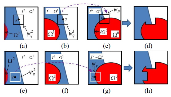
    In this work, we modify the original exemplar based inpainting technique to recover the textured regions in the occluding region using the above-mentioned advantage. We call the modified exemplar based inpainting technique the neighboring elemental image exemplar based inpainting (NEI-exemplar inpainting). Figure 4 shows the concept of the proposed NEI-exemplar inpainting technique. For consistency, we use similar notations as in [22].

    Figure 4(c) illustrates the elemental image (I0) under consideration, while Fig. 4(a) and (b) are two left hand-side neighboring elemental images(I1 and I2) . The red colored region (Ω0) in Fig. 4(c) represents the occluding object region which has to be inpainted by the proposed method, and ∂Ω0 denotes its boundary. The regions I0 - Ω0, I1 - Ω1 and I2 - Ω2 represent the source regions which provide for the samples used in the inpainting. The inpainting process starts from the boundary of Ω0, i.e., ∂Ω0. That is, for a point p on ∂Ω0, we put a square patch ψp centered at p. This square patch contains the region ψp ∩ (I0 - Ω0) for which the data is already filled, and the region ψp ∩ Ω0 in which the data has to be filled by the NEI-exemplar inpainting. The region is filled from the patch lying in the source region which region is most similar to the already filled region ψp ∩ (I0 - Ω0). Here, we denote the center of the patch in the source region as q. The top row in Fig. 4 represents the first inpainting step, while the bottom row represents the second inpainting step. It is assumed in the top row that the most similar square patch(ψq1) is found in Fig. 4(b), while the patch ψq2 in Fig. 4(a) could also be a candidate. The partial part in the patch ψq1 which corresponds to the occluding region part in ψp is copied into ψp ∩ Ω0. By filling in the region ψp ∩ Ω0, a partial filling of the whole occluding region is achieved as can be seen in Fig. 4(d). Likewise, the bottom row in Fig. 4 shows the second partial filling of the occluding region by the same procedure. Here, it is assumed that the most similar square patch is found in Fig. 4(e). The result of filling in the occluding region inside ψp in Fig. 4(g) is shown in Fig. 4(h). The partial filling process is repeated until the occluding region becomes totally filled.

    As can be seen in Fig. 4, unlike the original exemplar based inpainting technique, the best-match sample is found from the neighboring elemental images and not from the elemental image under consideration. In other words, the source region lies in neighboring elemental images. Therefore, the problem is formulated as
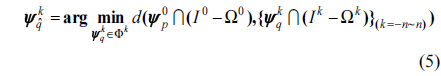
    image

    where k denotes the k-th neighboring elemental image. The function d(ΩAB) in (5) is a distance function that calculates the similarity distance between the two patch regions ΩA and ΩB. As in [22], we let the distance function d be the sum of squared differences (SSD) of the already filled pixels in the two patch regions.

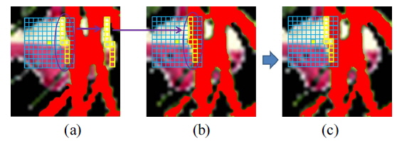
    Figure 5 is an exemplary image which shows how the proposed method fills in the data missing region. Figure 5(b) is the elemental image under consideration, where the red region shows the data missing region. An 11 × 11 window is applied on Fig. 5(b), which searches for the window which has the most similar region in the neighboring elemental image (Fig. 5(a)). Then, the non-occluded region in the window in Fig. 5(a) is copied to the region which corresponds to the occluding region in Fig. 5(b). Figure 5(c) shows the copied result. Thus, a part of the occluding region has been recovered by the NEI-exemplar based inpainting. This procedure is iteratively applied to the elemental image in Fig. 5(b) until all the occluding regions are recovered.

    After all the occluding regions are recovered, the CIIR is applied on the recovered elemental image array to result in the reconstructed 3-D image.

    III. EXPERIMENTS AND RESULTS

    The setup of the pickup stage in our experiments is as shown in the ‘pickup stage’ diagram shown in Fig. 1. The target 3-D objects are the ‘faces’ which are occluded by a ‘tree’. The target and the occluding objects are located ZT = 50 mm and ZO = 30 mm from the lenslet array away, respectively. We used five different ‘face’ images as the target objects which are shown in Fig. 6(a). The occluding ‘tree’ object is shown in Fig. 6(b).

    The lenslet array used in the experiments has 30 × 30 lenslets where each lenslet has a diameter of 5 mm. Each lenslet has a resolution of 30 × 30 pixels, and therefore the total number of pixels in the lenslet array becomes 900 × 900 pixels. Using this lenslet array, the partially occluded ‘face’ object was recorded to result in the 900 × 900 pixel elemental image array shown in Fig. 6(c).

    First, the MC-DE method is applied to the recorded elemental images to obtain the depth field image. This is shown in Fig. 2 for the case of using the fifth face image in Fig 6(a). Then, the level set bimodal segmentation is applied to the depth map of Fig. 2 to obtain the mask map. Here, we let the parameter α in (2) be 1, so that the mask values in the mask map converge to 1 or -1 depending on whether the corresponding pixel belongs to the object region or background region. The final mask map is shown in Fig. 3(h).

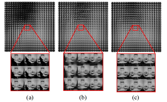
    Finally, we applied the proposed NEI-exemplar inpainting method using the mask map as the indication map of the data missing region. Figure 7 compares the inpainting result of the linear inpainting method and the proposed method. Figure 7(a) shows the elemental image array where the occluding object has been removed but the occluding region is left as a data missing region. Figure 7(b) and (c) show the elemental image arrays where the data missing region is filled in by the original linear inpainting and the proposed NEI-exemplar inpainting method, respectively. It can be seen that the linear inpainting method can fill in the missing data, but also results in some blurry artifacts. In comparison, the proposed NEI-exemplar inpainting method reconstructs the textural data in the missing region better than the linear inpainting method.

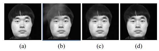
    Next, we reconstructed the 3-D plane images using the CIIR method as shown in Fig. 8. Figure 8 shows the 3-D plane images of the fifth ‘face’ image reconstructed by different methods. It can be observed from Fig. 8(b), that the occlusion produces serious noises in the reconstructed image. The LI-CIIR can relieve the problem to a large extent as can be seen in Fig. 8(c). However, there still remain some errors in the brightness values in regions where the occluding object has occluded the target object. This is due to the blurring artifact in the elemental images caused by the linear inpainting. In comparison, the proposed method can improve the visual quality of the reconstructed image as can be seen in Fig. 8(d).

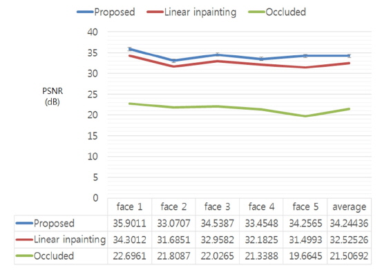
    We measured the peak signal-to-noise ratio (PSNR) for all the reconstructed plane images for a quantitative comparison between the different methods. Figure 9 shows the PSNR results for the five face images used in the experiment. The linear inpainting based CIIR and the proposed NEI exemplar based inpainting using CIIR show high PSNR improvements over the conventional CIIR method. While both of the inpainting based CIIR methods show large improvements over the conventional CIIR, the proposed method shows a higher PSNR improvement than the linear inpainting based CIIR, thus revealing the superiority to the linear inpainting based CIIR.

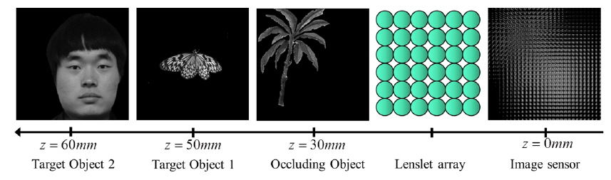
    Finally, we performed an experiment on an elemental image array which is obtained by a pickup setup as shown in Fig. 10. There are two target objects with different depths where ‘target object 1’ lies at ZT1 = 50 mm and ‘target object 2’ at ZT2 = 60 mm. These targets are occluded by the ‘tree’ object which lies at ZO = 30 mm. Furthermore, the ‘target object 2’ has a textured surface.

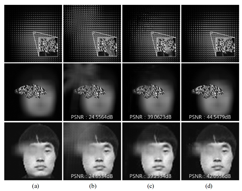
    Again, we removed the occluding ‘tree’ object from the elemental image array and reconstructed the 3-D image at planes with depths of z = 50 mm and z = 60 mm, respectively. The second and the third rows of Fig. 11 show the reconstructed 3-D images reconstructed at z = 50 mm and z = 60 mm, respectively. Only the target object which has the same depth as the plane at which the 3-D image is reconstructed becomes focused while the target object having a different depth becomes out of focus. The third row has some blurred region in it, which is due to the fact that ‘target object 1’ lies before ‘target object 2’, and because we only eliminated the occluding object and not ‘target object 1’. Here, it can be seen that the difference in the PSNR value between the proposed method and the linear inpainting based CIIR is larger than shown in Fig. 9.

    This is due to the fact that ‘target object 1’ has a textured surface which the proposed method can recover much better than the linear inpainting based CIIR.

    IV. CONCLUSION

    We proposed a method which can recover not only smooth data but also textured data in the data missing region caused by the partial occlusion of the occluding object. To this aim, the proposed method fills in the data missing region with exemplars obtained from neighboring elemental images. It has been shown experimentally, that the proposed method can recover textural regions in the elemental images, while other conventional CIIR methods including the linear inpainting based CIIR method cannot. This results in a 3-D image reconstruction better than those using conventional methods. It is expected that the proposed method can be used in several applications where the target object has to be clearly visualized and recognized in spite of a partial occlusion.

참고문헌
  • 1. Stern A., Javidi B. 2006 “Three-dimensional image sensing, visualization, and processing using integral imaging,” [Proc. IEEE] Vol.94 P.591-607 google cross ref
  • 2. Hong S.-H., Jang J.-S., Javidi B. 2004 “Three-dimensional volumetric object reconstruction using computational integral imaging,” [Opt. Express] Vol.12 P.483-491 google cross ref
  • 3. Park J.-H., Hong K., Lee B. 2009 “Recent progress in threedimensional information processing based on integral imaging,” [Appl. Opt] Vol.48 P.H77-H94 google cross ref
  • 4. Shin D.-H., Kim E.-S., Lee B. 2005 “Computational reconstruction technique of three-dimensional object in integral imaging using a lenslet array,” [Jpn. J. Appl. Phys.] Vol.44 P.8016-8018 google cross ref
  • 5. Shin D.-H., Kim M.-W., Yoo H., Lee J.-J., Lee B., Kim E.-S. 2007 “Improved viewing quality of 3-D images in computational integral imaging reconstruction based on round mapping model,” [ETRI J.] Vol.29 P.649-654 google cross ref
  • 6. Yoo H. 2011 “Artifact analysis and image enhancement in three-dimensional computational integral imaging using smooth windowing technique,” [Opt. Lett.] Vol.36 P.2107-2109 google cross ref
  • 7. Shin D.-H., Kim E.-S. 2008 “Computational integral imaging reconstruction of 3D object using a depth conversion technique,” [J. Opt. Soc. Korea] Vol.12 P.131-135 google cross ref
  • 8. Jang J.-Y., Shin D., Kim E.-S. 2014 “Optical three-dimensional refocusing from elemental images based on a sifting property of the periodic δ-function array in integral-imaging,” [Opt. Express] Vol.22 P.1533-1550 google cross ref
  • 9. Jang J.-Y., Ser J.-I., Cha S., Shin S.-H. 2012 “Depth extraction by using the correlation of the periodic function with an elemental image in integral imaging,” [Appl. Opt.] Vol.51 P.3279-3286 google cross ref
  • 10. Shin D.-H., Yoo H. 2008 “Scale-variant magnification for computational integral imaging and its application to 3D object correlator,” [Opt. Express] Vol.16 P.8855-8867 google cross ref
  • 11. Kim C., Park S.-C., Kim E.-S. 2009 “Computational integralimaging reconstruction-based 3-D volumetric target object recognition by using a 3-D reference object,” [Appl. Opt.] Vol.48 P.H95-H104 google cross ref
  • 12. Hwang D.-C., Shin D.-H., Kim S.-C., Kim E.-S. 2008 “Depth extraction of three-dimensional objects in space by the computational integral imaging reconstruction technique,” [Appl. Opt.] Vol.47 P.D128-D135 google cross ref
  • 13. Cho M., Javidi B. 2010 “Three-dimensional visualization of objects in turbid water using integral imaging,” [J. Display Technol.] Vol.6 P.544-547 google cross ref
  • 14. Jang J.-Y., Hong S.-P., Shin D., Lee B.-G., Kim E.-S. 2014 “3D image correlator using computational integral imaging reconstruction based on modified convolution property of periodic functions,” [J. Opt. Soc. Korea] Vol.18 P.388-394 google cross ref
  • 15. Zhang M., Piao Y., Kim E.-S. 2010 “Occlusion-removed scheme using depth-reversed method in computational integral imaging,” [Appl. Opt.] Vol.49 P.2571-2580 google cross ref
  • 16. Shin D.-H., Lee B.-G., Lee J.-J. 2008 “Occlusion removal method of partially occluded 3D object using sub-image block matching in computational integral imaging,” [Opt. Express] Vol.16 P.16294-16304 google cross ref
  • 17. Lee B.-G., Shin D. 2010 “Enhanced computational integral imaging system for partially occluded 3D objects using occlusion removal technique and recursive PCA reconstruction,” [Opt. Commun.] Vol.283 P.2084-2091 google cross ref
  • 18. Lee J.-J., Lee B.-G., Yoo H. 2011 “Image quality enhancement of computational integral imaging reconstruction for partially occluded objects using binary weighting mask on occlusion areas,” [Appl. Opt.] Vol.50 P.1889-1893 google cross ref
  • 19. Lee J.-J., Shin D., Yoo H. 2013 “Image quality improvement in computational reconstruction of partially occluded objects using two computational integral imaging,” [Opt. Commun.] Vol.304 P.96-101 google cross ref
  • 20. Lee B.-G., Ko B.-S., Lee S.-H., Shin D. 2015 “Computational integral imaging reconstruction of a partially occluded threedimensional object using an image inpainting technique,” [J. Opt. Soc. Korea] Vol.19 P.248-254 google cross ref
  • 21. Garcia D. 2010 “Robust smoothing of gridded data in one and higher dimensions with missing values,” [Comput. Stat. Data An.] Vol.54 P.1167-1178 google cross ref
  • 22. Criminisi A., Perez P., Toyama K. 2004 “Object removal by exemplar-based image inpainting,” [IEEE Trans. Image Process] Vol.13 P.1200-1212 google cross ref
  • 23. Ryu T.-K., Lee B.-G., Lee S.-H. 2015 “Mutual constraint using partial occlusion artifact removal for computational integral imaging reconstruction,” [Appl. Opt.] Vol.54 P.4147-4153 google cross ref
  • 24. Lee S.-H., Seo J.-K. 2006 “Level set-based bimodal segmentation with stationary global minimum,” [IEEE Trans. Image Process.] Vol.15 P.2843-2852 google cross ref
OAK XML 통계
이미지 / 테이블
  • [ FIG. 1. ]  Overall diagram of the proposed NEI-exemplar inpainting method.
    Overall diagram of the proposed NEI-exemplar inpainting method.
  • [ ] 
  • [ FIG. 2. ]  Disparity vector map obtained by the MC-DE method (a) component of the disparity vector (b) component of the disparity vector.
    Disparity vector map obtained by the MC-DE method (a)  component of the disparity vector (b)  component of the disparity vector.
  • [ ] 
  • [ ] 
  • [ ] 
  • [ FIG. 3. ]  Obtaining the weight mask by the level set based bimodal segmentation method (a)~(g) evolution of the level set function (φ)(h) resultant weight mask.
    Obtaining the weight mask by the level set based bimodal segmentation method (a)~(g) evolution of the level set function (φ)(h) resultant weight mask.
  • [ FIG. 4. ]  Explaining the exemplar based inpainting process of the proposed method. (a)(e) second left neighboring elemental image (b)(f) first left neighboring elemental image (c)(g) elemental image under consideration (d)(h) inpainted result. Top row: first inpainting step Bottom row: second inpainting step.
    Explaining the exemplar based inpainting process of the proposed method. (a)(e) second left neighboring elemental image (b)(f) first left neighboring elemental image (c)(g) elemental image under consideration (d)(h) inpainted result. Top row: first inpainting step Bottom row: second inpainting step.
  • [ ] 
  • [ FIG. 5. ]  Exemplary image explaining the procedure of filling in the missing region by the NEI-exemplar based inpainting method (a) neighboring elemental image (b) elemental image under consideration (c) elemental image after the first iteration of the filling-in procedure.
    Exemplary image explaining the procedure of filling in the missing region by the NEI-exemplar based inpainting method (a) neighboring elemental image (b) elemental image under consideration (c) elemental image after the first iteration of the filling-in procedure.
  • [ FIG. 6. ]  Test images (a) five ‘face’ images used as the target object in the experiment (b) occluding object (c) elemental image array of the fifth ‘face’ image with occlusion.
    Test images (a) five ‘face’ images used as the target object in the experiment (b) occluding object (c) elemental image array of the fifth ‘face’ image with occlusion.
  • [ FIG. 7. ]  Elemental images (a) before inpainting (b) after inpainting with original linear inpainting (c) after inpainting with proposed NEI-exemplar based inpainting.
    Elemental images (a) before inpainting (b) after inpainting with original linear inpainting (c) after inpainting with proposed NEI-exemplar based inpainting.
  • [ FIG. 8. ]  (a) Original 3-D plane. Reconstructed 3-D plane images by (b) the conventional CIIR (c) the LI-CIIR method (d) the proposed method.
    (a) Original 3-D plane. Reconstructed 3-D plane images by (b) the conventional CIIR (c) the LI-CIIR method (d) the proposed method.
  • [ FIG. 9. ]  Comparing the PSNR values of the reconstructed 3-D images.
    Comparing the PSNR values of the reconstructed 3-D images.
  • [ FIG. 10. ]  Pickup process of two target objects with different depths and one occluding object.
    Pickup process of two target objects with different depths and one occluding object.
  • [ FIG. 11. ]  First row: Elemental image array. Second row: 3-D plane reconstructed at z = 50 mm Third row: 3-D plane reconstructed at z = 60 mm (a) without occlusion (b) with conventional CIIR (c) with LI-CIIR method (d) with proposed method.
    First row: Elemental image array. Second row: 3-D plane reconstructed at z = 50 mm Third row: 3-D plane reconstructed at z = 60 mm (a) without occlusion (b) with conventional CIIR (c) with LI-CIIR method (d) with proposed method.
(우)06579 서울시 서초구 반포대로 201(반포동)
Tel. 02-537-6389 | Fax. 02-590-0571 | 문의 : oak2014@korea.kr
Copyright(c) National Library of Korea. All rights reserved.