Surgical lighting systems can essentially be categorized as halogen or LED according to the light source. Most importantly, surgical lighting should provide a clear field of view without shadow and should not cause visual fatigue for the surgeon.
Thus, surgical lighting needs to be uniform, where the Ec, the central illuminance, is typically a minimum of 40,000 lx and maximum of 160,000 lx. To differentiate the colors of organic tissue, the color rendering index (Ra) should be between 85 and 100, and in the case of a blackout, 50% of the illumination intensity needs to be restored within 5 seconds. While conventional surgical lights use halogen as the light source, LED is recently starting to replace halogen owing to the advancement of LED technology [1].
Halogen-based surgical lights have filaments concentrated in a narrow space and are subject to over-heating, which can cause drying of exposed organic tissues, as well as unwanted coagulation of blood. Plus, the heat emitted from halogen-based surgical lights can increase the head temperature of surgeons, causing fatigue and diminishing the surgeon's concentration. While the initial cost of halogen-based surgical lights is comparatively cheap, they have a short life cycle and high power consumption. Furthermore, a high color temperature of 3,000 K produces orange-colored light, which makes it difficult to differentiate the colors of organic tissues and capillary vessels.
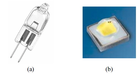
In contrast, LED-based surgical lights have a very low radiant heat, resulting in minimal drying, and a color temperature above 4,000 K can minimize surgical fatigue and help to maintain optimal conditions for operations. Moreover, LED-based surgical lights have a long life cycle, between 20,000 and 40,000 hours, and low power consumption [2-4]. Figure 1 shows a halogen bulb and an LED package commonly used in surgical lights.
Various studies have already compared the advantages of LED over halogen light sources for surgical lighting. For example, Cheon
However, this paper discusses a hybrid optical system that combines the advantages of conventional reflector- and lens-type systems for application in an LED surgical light. First, Chapter II briefly outlines previously developed lens and reflector-type optical systems, and then Chapter III discusses the details of the proposed hybrid optical system. Experimental results using prototypes of the single and hybrid optical systems are presented in Chapter IV, followed by some conclusions.
II. REVIEW OF EXISTING SINGLE OPTICAL SYSTEMS
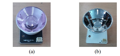
Figure 2 shows a lens-type and reflector-type single optical system using a single LED source developed by our research team.
As shown in Fig. 2(a), the lens-type(Convex Lens) system uses a light distribution method that collects light in the center of the lens. Yet, the convex lens causes a chromatic aberration due to a difference in the diffractive index, which produces color distortion and reduces the concentration of the surgeon. Also, the typical thickness of the convex lens is over 10 mm, which requires a longer manufacturing time and has a higher percent of being defective due to lens compression. Moreover, an additional lens is needed inside the light distribution parts, which adds weight and affects the structural reliability of the pendant system supporting the surgical light.
As shown in Fig. 2(b), the reflector-type system, which is lighter than the lens-type system, includes a reflector plate at the center of the light source to improve the uniformity of the light, where the funnel-shaped reflector surface is facet-treated with hexagon forms and aluminum-coated [13]. However, the reflector-type system has a lower Ec.
Thus, a hybrid single optical system that can produce an Ec comparable to a lens-type system and is lightweight comparable to a reflector-type system is introduced in the following chapter.
III. SYSTEM DESIGN AND FABRICATION
3.1. Design Concept of Single Optical System
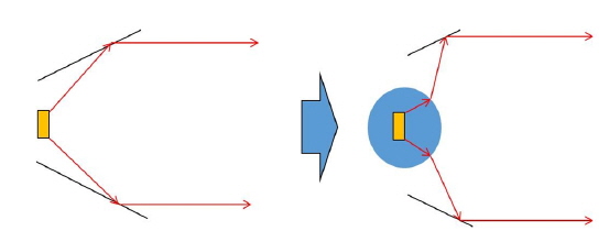
A single optical system is a unit module that generates surgical light and determines the performance of that surgical light. Plus, the overall weight of the single optical system directly influences the weight of the surgical light. Therefore, the design goal was to reduce the overall weight of the system, maintain a high Ec, and consider future productivity. Figure 3 shows the basic concept of the proposed hybrid single optical system structure. The lens, the primary optical module, sends the incoming light to the side as much as possible, where the fundamental idea is to reduce the light distribution to the front and obtain a high-angle beam spread according to the principle of total reflection. Thus, while reducing the size of the lens, representing most of the optical system, the LED light source can still produce an illumination intensity equivalent to that of a lens-type system, as shown in Fig. 2(a). Furthermore, the side thickness of the surgical light can be reduced by decreasing the height of the reflector, as shown in Fig. 3.
3.2. Design and Fabrication of Optical System
Light source data provided by the manufacturer were applied to the design and optimization using LIGHTTOOLS. The resulting lens was then analyzed using SPEOS CATIA for reflector optimization and assembly modeling. Two tools were used because SPEOS CATIA is not equipped with an optimization module, while LIGHTTOOLS does not have a function for reflector modeling and form change, and has difficulty with assembly modeling.
3.2.1. Single Optical System
Based on the fundamental objectives, the design process of the single optical system was as follows.
1) LED selection
- The features of medical devices required an LED package with a high CRI value (> 90) and color temperature around 4000 K - The concept structure required an LED package with a high beam spread angle (150°), which is higher than that of a typical package (120°) - To satisfy the above conditions, LCW-CRDP.CC from OSRAM was selected.
2) Lens design
- The lens needed to restrict the initial direct LED light and divert it to the side as much as possible - The peak value for the angle of the beam spread in the design program was set at 80° (initially 0°) - The lens surface was determined as a free-form surface and defined with finite points, the locations of which were set as variables. - The lens form was derived using the optimization module of the design program
3) Reflector design
- Patterns were made on the radiation field (1m distant) by reflecting the beam coming from the lens - The focal point of the reflector was optimized, as the light passed through the lens, unlike an LED, where the light comes directly from the source - The reflector was divided into multi-facets to increase the uniformity of the pattern on the radiation surface, and the curvature of the reflecting surface was optimized by trial-and-error.
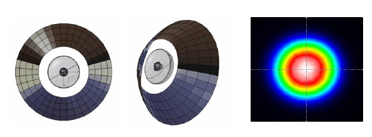
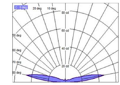
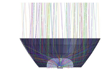
Figure 4 shows the output angle of the beam spread for the incoming light from the completely designed optical system. The angle of the beam spread was approximately 80°, as initially designed. Figure 5 shows the simulation result for the beam path when the reflector was installed.
The design conditions of the prototype were determined using an iterative fundamental design procedure for the single optical system. Through an iterative simulation, the external and internal diameters of the reflector were optimized at 43 mm and 20 mm, respectively, with a height of 15 mm. The Ec was approximately 4121 lx, and D10, the light field diameter that reached 10% of the Ec, was 19.0 cm. Plus, the ratio of D50 (the light field diameter that reached 50% of the Ec) to D10, which is the standard of surgical light according to IEC 60601-2-41 [14], was 69%. Thus, the above structural specifications were used as the basic design data for the hybrid optical system.
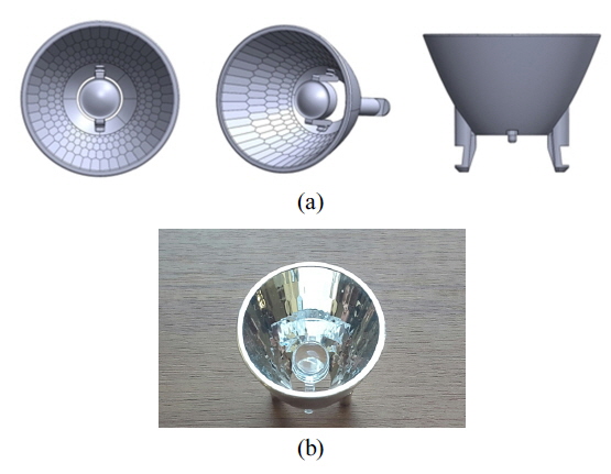
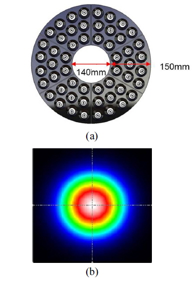
Figure 7(a) shows 3D drawings based on the simulation data, while Fig. 7(b) shows the hybrid optical system prototype, where the lens is located in front of the LED source, and the reflecting surface is multi-faceted, like a reflector-type system.
3.2.2. Complex Optical System
After designing the single optical system, a complex optical system was designed based on channel composition using a single module array and a focus angle design for each channel’s single optical system. Thus, one assembly consisted of 9 single optical systems, and 6 assemblies comprised the entire beam distribution surface, as shown in Fig. 8. Optical simulations were iterated until the Ec, D10, and D50/D10 reached approximately 128,110 lux, 20.6 cm, and 63%, respectively.
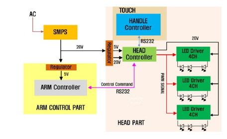
The control system of the proposed surgical light consists of a main controller located on the arm that supports the surgical light, a handle controller located at the light head, and head controller located inside the light head that receives signals from the main and handle controllers. The head controller transmits PWM control signals, according to commands from touch panels at the main or handle controller, to the driver section of the LED that is connected to the single optical module. In this study, the main and handle controllers were operated based on a CISC-affiliated micom and communicated with each other using the RS232 protocol.
Thus, the surgical light consisted of 54 single optical systems that were controlled based on 6 assembles that were each connected to an LED driver board with a 3 PWM input port. Depending on the output pattern of the surgical light, the 54 optical modules were grouped into specified channels to control the illumination intensity. Figure 9 shows a schematic diagram of the proposed surgical light's control system.
IV. PERFORMANCE MEASUREMENT RESULTS
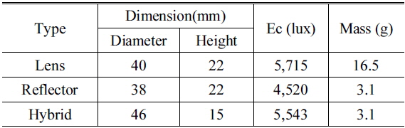
The prototype was compared with existing lens- and reflector-type systems based on measuring the Ec. The current input for each single optical system was set at 350mA and the output beam measurements were taken at a distance of 1m using a MILOTA CL-200A illuminometer. The pattern outputs on the beam distribution surface were also observed. Table 1 summarizes the physical aspects of each optical module including its mass.
[TABLE 1.] Comparison of single optical systems according to structure
Comparison of single optical systems according to structure
When considering the structural features, the hybrid type had the largest diameter, yet the smallest height, which was almost half the height of the other types. While the lens type showed the highest Ec, the reflector and hybrid types reached 79.1% and 97% of the Ec achieved by the lens type, respectively. However, the lens type had the greatest mass, whereas the reflector and hybrid types only had 18.8% of the mass of the lens type. Finally, the height of the hybrid type was 32% lower than that of the reflector and lens types. Therefore, the hybrid single optical system showed overall advantages when compared with the lens and reflector types, as its mass was as light as the reflector type, while its Ec was similar to that of the lens type. Plus, the hybrid had a slimmer structure with a lower height than the other types.
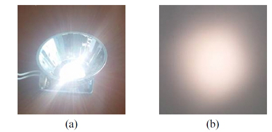
Figure 10(a) shows the operation of the fabricated single optical system prototype, and Fig. 10(b) shows the pattern output on a white wall at a distance of 1m from the light source. As shown in Fig. 10(b), the beam exhibited a circular shape and comparatively uniform distribution.
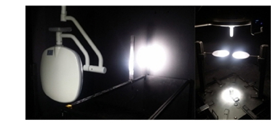
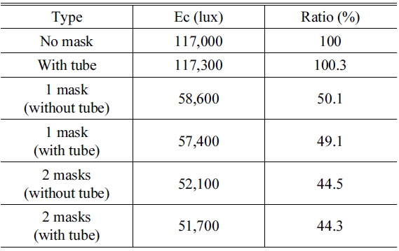
The shadow dilution performance was evaluated according to IEC standards [14] using a mock-up system of an LED surgical light composed of 54 hybrid optical systems. The measurement of the Ec was set-up as shown in Fig. 11 for 5 cases with about 20 cm ± 10% pattern output: no mask with a tube, 1 mask, 1 mask with a tube, 2 masks, and 2 masks with a tube. No mask attained an Ec of 117,000lux which was 91.3% of the optical simulation result, and the other measurement results are summarized in Table 2. The illumination depth, which determines the application range of the surgical light, was measured at 60% and 20% of the Ec, and the results are summarized in Table 3.
[TABLE 2.] Shadow dilution test results

Shadow dilution test results
[TABLE 3.] Illumination depth measurements
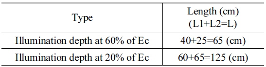
Illumination depth measurements
This study presented an LED hybrid single optical system, which combines the advantages of the high illumination intensity from a lens-type system and the light weight from a reflector-type system, along with an LED surgical light composed of hybrid single optical systems.
Through iterative simulations using optical design software, fundamental reflector design data were collected for the lens design of a single optical system and beam analysis, and then applied to the prototype design of a single optical system. Using evidence from repeated simulations with single optical systems, a complex optical system was designed for an optimal beam distribution surface based on a composite of 54 single optical modules.
Measurements of the prototype’s central illuminance and weight verified that the hybrid single optical system is more advantageous than conventional systems, plus the shadow dilution performance was evaluated using a mock-up surgical light. Future research will focus on decreasing the thickness of the LED surgical light, while considering the characteristics of the central illuminance. Thus, with added functional improvements, such as illuminance characteristics depending on variations of the pattern output, shadow dilution performance, and operational convenience, the proposed LED surgical light based on a hybrid single optical system is expected to earn more marketability in the future.