Due to the expansion of multimedia services such as video on demand, video-conferencing, e-learning, interactive services, and VOIP, the demand for an optical fiber based high speed Internet network has increased significantly. Although optical fibers have been designed primarily for optical communication, they show promise in a wide range of application areas including coupling [1], fiber lasers [2], optical sensors [3-9], imaging and spectroscopy [10, 11], and biomedical engineering [12]. In most of the cases, micro-structuring of the optical fibers is required to produce application specific optical fibers. During the last several decades, laser assisted micro-patterning has attracted researchers as well as the micro-machining industry. Lasers have proved their versatility in patterning various micro/nano-scale structures in various materials including optical fibers [3-7, 9, 11-25]. Since the arrival of the first functional CO2 laser in 1964, they have played significant roles in a large variety of application areas [14-22].
Initially, CO2 laser beams were extensively utilized for melting and polishing of transparent materials [14-16]. Nowadays, CO2 lasers have been widely used for micro-patterning of various materials [17-19] and micro-lens formation inside transparent materials [20-22]. Y. S. Kim
Formation of micro-lenses has attracted many researchers due to their applications primarily in imaging and spectroscopy. However, micro-lenses can also be used to connect light sources to detectors, modulators, and optical fibers. In-fiber micro-lenses can also be used for the surgery of soft tissues. M. Wakaki
This paper demonstrates a novel technique of fabricating a large variety of micro-lensed fibers with convex, concave, and conical shapes using a CO2 laser assisted reshaping technique. The end faces of the single-mode fibers have been reshaped by focusing the CO2 laser beam vertically on top of the fiber tips. We also investigated the impact of laser energy, number of laser irradiations, and the rotation angle of angled fibers on the angle of the lenticular fiber tip. The fiber angle shows an increasing trend with the increase of rotation angle and the number of laser repetitions. More importantly, the processing time has decreased significantly to several seconds from 5 to 10 minutes for mechanical polishing. Furthermore, we examined the radiation pattern of light coming out from the micro-lensed optical fibers. We strongly believe that the proposed technique would be suitable for fabricating various kinds of lenses in optical fibers.
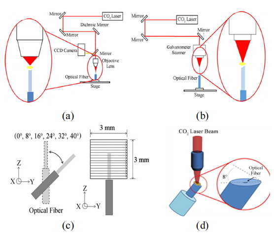
During our experiments, we selected single-mode optical fibers as samples having core/clad diameter of 8 μm/125 μm and core and cladding refractive indexes of 1.467 and 1.445. To reshape the end faces of the single-mode optical fibers, we utilized a pulsed CO2 laser (Coherent, C-55L) operating at the central wavelength (
In contrast, to fabricate lenticular fiber tips of variable curvature, the CO2 laser beam with laser energy of 1 mJ was irradiated by means of a galvanometer scanner (magnification: 80×; focal length: 170 mm) on the end faces of the single-mode fibers at a scanning speed of 500 mm/s and a scanning step of 20 μm. Figure 1(b) represents the schematic diagram of the experimental setup for fabricating angled fiber of variable angles. The optical fibers were placed inside a mechanically rotatable holder placed on top of a 3-axis translation stage. The fiber holder was manually rotated from 0° to 40° to achieve the desired fiber angle where the laser beam was emitted 3 times (forward & backward) in a 3 mm×3 mm area, which is shown in Fig. 1(c). To examine the impact of the repetition of laser irradiation on the curvature of the fiber tip, the single-mode angled fiber was exposed up to 7 times (forward & backward) under the CO2 laser beam by positioning the angled fiber at an angle of 8°, which is illustrated in Fig. 1(d).
2.2. Measurements and Analysis
Various micro-lensed optical fiber samples were placed on the stage of an optical microscope to examine the structure of the fiber tips. To investigate the beam pattern and radiation pattern of light from the micro-lensed optical fibers, a He-Ne laser (ThorLabs, HRP 020-1) operating at the wavelength of 633 nm with power of 32 μW was passed through the optical fibers. A white screen was placed 50 mm away from the end face of the fibers. We captured the front and side view images of the radiation pattern for various micro-lensed fibers using a high resolution camera. Furthermore, we also simulate the beam pattern and radiation pattern of light from various micro-lensed optical fibers using the LightTools simulator.
As mentioned before, we fabricated micro-lensed fibers of various shapes by a CO2 laser assisted reshaping technique. By varying the laser energy from 0.16 to 0.3 mJ, we encoded convex, concave, and conical shaped fiber tips. We also altered the fiber angle by polishing of the fiber tip several times by means of a CO2 laser beam with laser energy of 1 mJ at a scanning speed of 500 mm/s and a scanning step of 20 μm.
3.1. Fabrication of Plano-convex Micro-lensed Optical Fiber
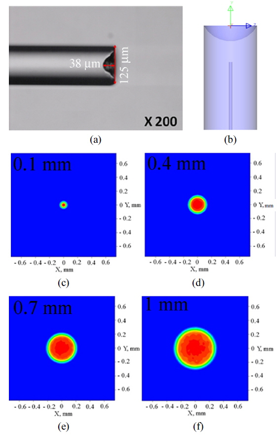
In order to convert the plane surface of the optical fiber of Fig. 2(a) to a plano-convex shape, a CO2 laser beam of 0.3 mJ energy was focused on the top surface of the vertically positioned single-mode optical fiber. Due to the exposure of the laser beam for approximately 5 seconds, the end face of the optical fiber was melted and consequently reshaped to the plano-convex shape (plano-convex micro-lensed fiber), the optical microscope image of which is depicted in Fig. 2(b). The radius of curvature (
where
Using the LightTools simulator, we simulate the beam profile of the traditional single-mode optical fiber of Fig. 2(a) and the plano-convex micro-lensed fiber of Fig. 2(b) at different positions (0.1 mm, 0.4 mm, 0.7 mm, and 1 mm) after the end face of the fibers. The simulation result regarding the beam profile of the unpatterned single-mode optical fiber is illustrated in Fig. 2(d), whereas the beam profile of the plano-convex lenticular fiber is shown in Fig. 2(f).
Due to refraction, the natural tendency of any incoherent light coming out from optical waveguide is to broaden over distance. The beam profile of Fig. 2(d) indicates that the circular light beam is widened with the increase of distance from the fiber tip. The diameter of the circular beam was 50 μm when it was observed 0.1 mm away from the fiber tip, which was increased to 362 μm at 1 mm distance from the fiber tip. Similar beam pattern, i.e. increasing trend with the increase of distance from the fiber tip, was detected for the plano-convex micro-lensed optical fiber of Fig. 2(e). Figure 2(f) gives us the diameter values of the circular light beam as 45 μm, 137 μm, 225 μm, and 305 μm for the positions of 0.1 mm, 0.4 mm, 0.7 mm, and 0.7 mm, respectively. Although the trends of beam profile is similar for the un-modified optical fiber tip and the convex fiber tip, the light through the plano-convex optical fiber has less broadening compared to unmodified fiber. This result signifies the nonpervasive nature of the plano-convex fiber tip.
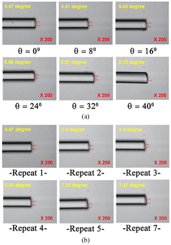
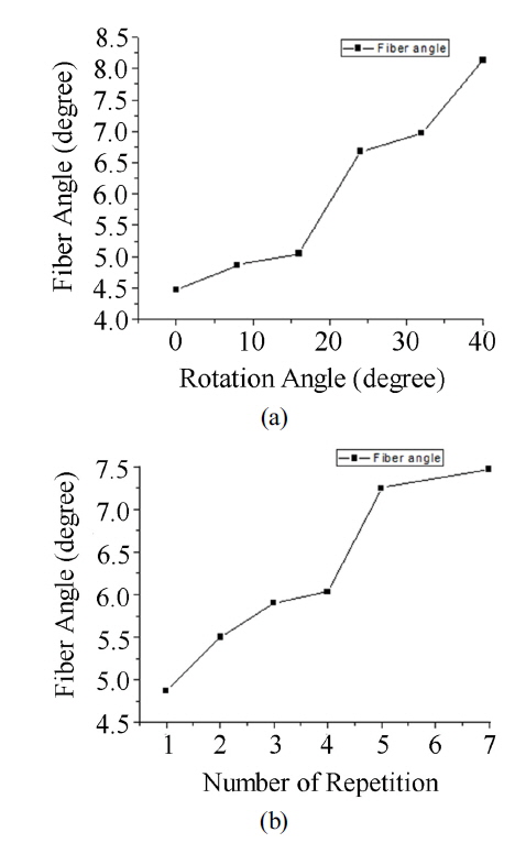
Furthermore, we investigated the variation of angle of single-mode angled fiber due to the variation of the rotation angle during laser processing and to the number of laser scannings. The optical fibers were vertically rotated with rotation angle varying from 0° to 40° and the CO2 laser beam was scanned 3 times (forward & backward) on the end faces of the optical fibers. Consequently, angled fibers of different angles varying from 4.47° to 8.13° have been evolved. Figure 4(a) shows the optical microscope images and the corresponding fiber angles of various angled fibers due to the variation of rotation angle. We also investigated the influence of number of laser irradiations on the angle of the fibers. In order to do so, we positioned an optical fiber at an angle of 8° and scanned the laser beam several times (maximum 7 times) by focusing the laser beam on the end face of the fibers. As a result, angled fibers with fiber angles in the range of 4.87° to 7.47° were detected. Figure 4(b) illustrates the optical microscope images and the corresponding fiber angles for variable number of CO2 laser irradiations. Figure 5 plots the fiber angles of the angled single mode optical fibers against rotation angle (Fig. 5(a)) and number of laser irradiations (Fig. 5(b)).
3.2. Fabrication of Plano-concave Micro-lensed Optical Fiber
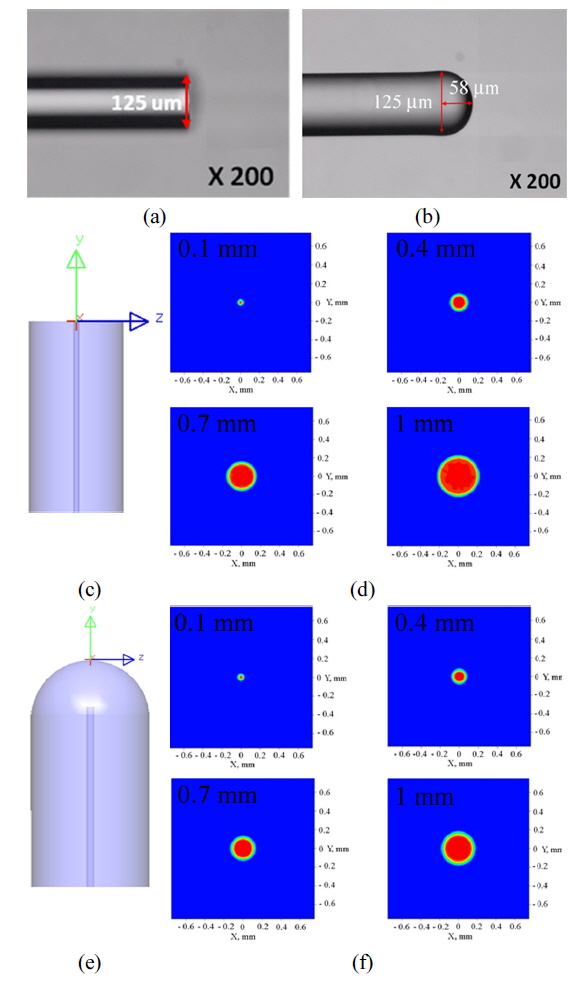
We also fabricated plano-concave micro-lensed optical fiber by exposure to the CO2 laser beam of 0.16 mJ energy for approximately 5 seconds. The optical microscope image of the plano-concave micro-lensed fiber is represented in Fig. 6(a). The
3.3. Fabrication of Conical-shape Micro-lensed Optical Fiber
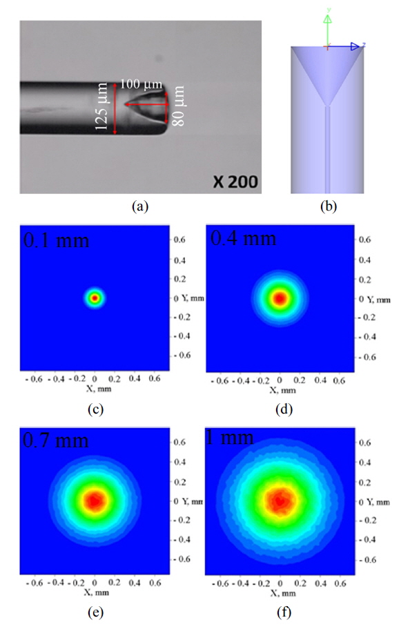
Conical-shape micro-lensed optical fiber was produced by irradiating a CO2 laser beam of 0.26 laser energy for approximately 5 seconds on top of a single-mode optical fiber. Consequently, the conical-shape fiber tip of Fig. 7(a) was evolved. The depth and diameter of the micro-cone were approximately 100 μm and 80 μm, as shown in the figure. The similar kind of conical micro-lensed fiber was designed during simulation, the schematic diagram of which is presented in Fig. 7(b). Figs. 7(c-f) shows the beam pattern of light at different positions after the end face of the conical fiber tip. The beam diameter of light at 0.1 mm, 0.4 m, 0.7 mm, and 1 mm distances were 227 μm, 600 μm, 967 μm, and 1.3 mm respectively. Compared to the concave micro-lensed fiber, the conical-shape fiber showed better pervasive property. As a consequence, the intensity of the light at the center was decreased significantly, as shown in Figs. 7(c-f). The beam diameter for all four cases is summarized in Table 1.
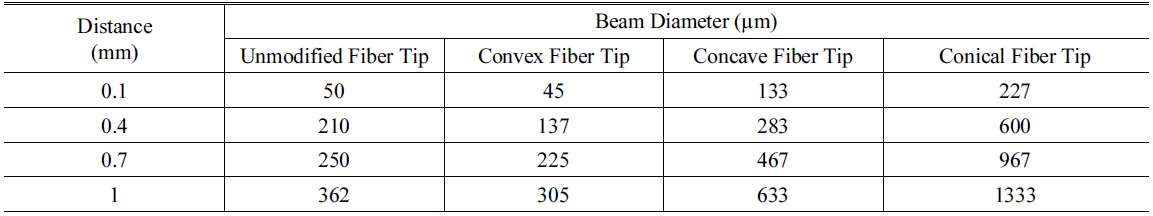
Beam diameter at different positions after the unmodified, convex, concave, and conical fiber tips
3.4. Emission Pattern of Light from Various Fibers
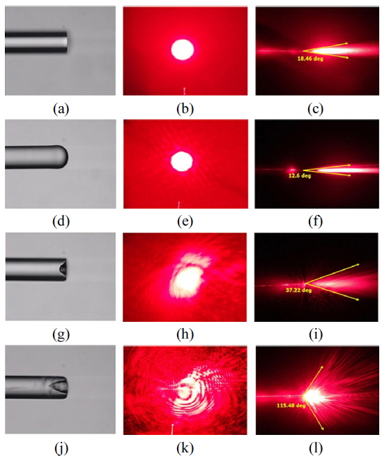
In order to examine whether the light beam is emitted circumferentially with respect to the optical axis, we investigate the emission pattern of light coming out from various fibers including the unmodified single-mode fiber and planoconvex, plano-concave, and conical-shape micro-lensed optical fibers. Figure 8 represents the radiation pattern of light from various optical fibers. The light beam from the unmodified fiber tip is concentrated into the direction parallel to the fiber axis, which is obvious from the front view of Fig. 8(b). From the side view of radiation pattern of the unmodified optical fiber we observed that, the light emitted at a maximum angle of 18.5°, as evident from Fig. 8(c). Like unmodified optical fiber, the plano-convex micro-lensed fiber showed circular radiation pattern, as depicted from Fig. 8(e). However, due to the nonpervasive nature of the convex fiber, the maximum radiation angle for the convex fiber tip reduced down to 12.6° (shown in Fig. 8(f)) indicating concentration of light in parallel with the fiber axis.
Figure 8(h) showed that the plano-concave fiber tip radiates light in multiple directions from the end face of the fiber tip indicating pervasive nature of the concave fiber tip. This result is also evident from the side view of the radiation pattern for the concave fiber tip. From Fig. 8(i) we determined the angle of light radiation for the plano-concave microlensed fiber as 37.2°. The highest angle of radiation (115.5°) was measured for the conical fiber tip, as shown in Fig. 8(l). This result exemplifies the conical fiber tip as the most pervasive micro-lensed fiber.
In summary, we fabricated various kinds of micro-lensed fiber tips including convex, concave, and conical shapes by means of a CO2 laser assisted beam shaping technique. We also examined the formation of variable angle single-mode fibers by varying the rotation angle during laser processing and number of CO2 laser irradiations. Experimental results showed that, with the increase of the rotation angle and laser repetition, the angle of the single-mode angled fiber was increased. Furthermore, we analyzed the beam profile and radiation pattern of the light beam coming out from the micro-lensed fibers. The convex and conical fiber tips showed pervasive nature and those radiated light in multiple directions, whereas unmodified and convex fiber tip radiates light in parallel to the fiber axis. The conical fiber tip showed highest radiation angle of 115.5°. We strongly believe that the proposed CO2 laser assisted fiber tips would be valuable in a large variety of applications areas. In the future, a precision machining method using a high order objective lens will be approached for making non-uniform beam to uniform in conical or concave shape of micro-lens.