Over the past decades, wireless communication, especially the mobile communication, has achieved rapid progress which satisfies the ubiquitous access requirements and thus, significantly improves the quality of daily life. However, the ability of wireless technology to further advance our society is now seriously challenged by the spectrum overcrowding problem, that is, the insufficient capacity of available spectrum to support the ever-increasing wireless data traffic [1]. To solve this problem, the millimeter wave communication, the Terabit communication and the optical wireless communication have been presented in succession for developing higher spectrum and obtaining larger bandwidth. Due to the large-scale deployment of white light-emitting-diode (LED) as the next-generation green lighting, the visible light communication (VLC), which utilizes the visible light radiations from LED to transfer information in line-of-sight free space, has been presented recently [2] as an attractive solution for indoor broadband wireless communication, since it combines the advantages of both optical access and wireless access.
However, the modulation bandwidth of the LED itself is actually quite limited [3], so much attention has been paid to the research of the techniques to increase the VLC system speed. Besides the advanced modulation schemes [4-6], multiplexing techniques are also basic methods to increase the system speed and network capacity. Many multiplexing mechanisms have been utilized in current wireless communication such as time-division-multiplexing (TDM), code-divisionmultiplexing, and space-division-multiplexing (SDM). However, TDM is still the only multiplexing mechanism utilized in VLC currently, and the implementation of other multiplexing mechanisms such as color-division-multiplexing (CDM) and polarization-division-multiplexing (PDM) has not been deployed in practical systems [7].
On the other hand, current research on VLC indoor deployment are based on the same network model as that presented in the original paper, a single 5×5×3 m3 room in which four LED lamps are deployed at the ceiling [2]. Both the illumination power and the information come from the electricity power line, and are then broadcast through all the LED lamps, realizing uniform lighting and signal distribution in the whole room. However, this broadcasting scheme is inefficient to be directly extended to a multi-room house scenario because in such manner the capacity of the whole network is only equal to the VLC system speed, and the network cannot support flexible user access and bandwidth allocation. One solution is to introduce a room-division-multiplexing (RDM) mechanism in which the information of a certain user will not be broadcast by all the LED lamps in the whole house, but only be broadcast by the lamps in the corresponding room in which the user locates. This scheme utilizes the spatial position of the LED lamps in different rooms as a novel dimension of resource for multiplexing, so it can be considered to be the first step to deploy SDM in VLC, which has great potential to increase network capacity in the future [8].
In such an RDM-based VLC network, how to maintain the service connectivity when the user makes a cross-room movement is a key problem. In this paper, we present a double-area positioning based cross-room switch solution. The remainder of the paper is organized as follows: Section II presents the RDM-based VLC network architecture; Section III provides the specific description of the proposed switch mechanism; Section IV shows the experimental platform and performance analysis.
II. RDM-BASED INDOOR VLC NETWORK
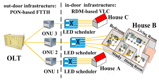
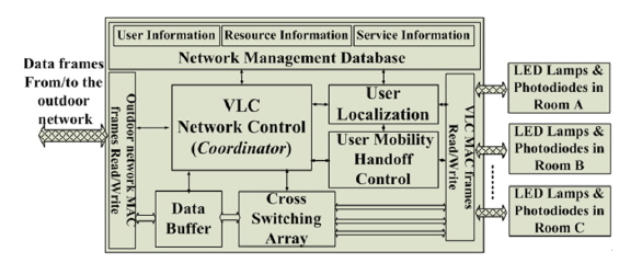
Figure 1 presents the architecture of RDM-based indoor multi-room VLC network. Currently, the passive optical network (PON) based fiber-to-the-home (FTTH) is an ideal scheme for outdoor broadband access due to the huge bandwidth of fiber, so in Fig. 1, we utilize PON as the outdoor access infrastructure.
In conventional broadcasting manner, user information from the outdoor power line is directly sent to all the LED lamps and broadcast in TDM manner to users, but in RDM scheme, it will be divided into different groups according to the user position. The LED lamps in one certain room then only broadcast the corresponding group of information for the users within that room. In such a scheme, the optical signal is still distributed evenly in each room, but the signals between adjacent rooms are separated naturally by the walls and doors without any interference. In conventional broadcasting, since all of the LED lamps transmit the same signal, the network capacity is equal to the capacity that a VLC system can offer. If we utilize RDM, the LED lamps in different rooms are broadcasting different signals simultaneously, so the network capacity and the bandwidth utilization efficiency are both increased. On the other hand, the RDM mechanism is compatible with other multiplexing and advanced modulation mechanisms such as TDM and orthogonal-frequency-division-multiplexing (OFDM), so in practical network deployment, the RDM is recommended to be employed together with these mechanisms to maximize the network capacity [9].
A new network device called LED scheduler is defined here to realize the service division and distribution operation. Figure 2 shows its specific functional modules. The service division and distribution are operated based on the user information in the MAC layer address header, so the scheduler is capable of recognizing and operating the data frames in both outdoor communication and indoor VLC MAC formats. The VLC network control module is the main part in the scheduler which is defined as the
To realize RDM, two software programs are required for user localization and cross-room control. If a user enters the house, the localization program starts to determine the room in which this user locates and stores the associated user information into the database. When a downlink data frame arrives, the LED scheduler reads out the MAC address, recognizes the user, searches the database, determines the destination room, and then generates an instruction to the cross switching array for transmitting this frame to the corresponding output port. On the other hand, although VLC is suggested to be deployed in low-mobility situations [7], the cross-room switch operation is unavoidable considering the user may move to another room using a mobile terminal in the presented multi-room house scenario. In such case, the user movement control program should be generated to switch the output port and modify the information in the database.
III. DOUBLE-AREA-POSITIONING BASED CROSS-ROOM SWITCH
Many VLC-based indoor positioning mechanisms have been presented [11, 12]; however, such mechanisms are only designed for indoor accurate positioning, but not for communication simultaneously. In these mechanisms the LED lamps in one room should send at least three different groups of signals to assist the user terminals for localization, but in our network, all the LED lamps in the same room are broadcasting the same information to the users within this room, so these positioning mechanisms are not suitable to be directly deployed in our network. In RDM scheme, the basic localization requirement is to differentiate the room where one user locates. The user uplink data frames from different rooms are first collected by different photodiodes (PDs), and then transmitted to different uplink ports in the scheduler, so the scheduler can use the uplink port number to differentiate the users in different rooms, and thus accomplish the user localization. However, this scheme is inefficient for handling the cross-room switch because the localization is determined after the user enters the room. If the user crosses the door, the information broadcasting in the original room may be lost and the communication would only be continued after the user is relocated in the new room. To solve this problem, the switch operation should be generated in advance when the user comes close to the door.
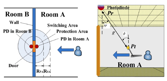
There are many handoff mechanisms in current mobile communication [13] in which the handoff procedure starts before the services disconnect, but the pre-condition to realize such handoff is the existence of an overlapped area between two adjacent cells in which the signals of both base stations are reachable, and the handoff can be generated in this area in advance. However, in our network, the optical signals between adjacent rooms are separated naturally by the walls and doors, so such handoff is not suitable. Here we design a novel double-area-positioning based switch mechanism shown in Fig. 3.
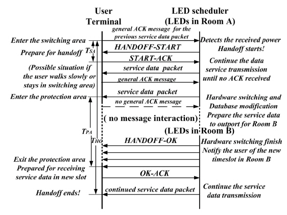
When the user passes through the door, there is always a short period in which the downlink signals of both rooms are unreachable, so we set a protection area in which the service transmission will be paused to guarantee the quality of service. Outside the protection area, there is an annular switching area for generating switch operation in advance. If a user enters the switching area, the scheduler sends a HANDOFF-START message to inform the user that data transmission will be paused for a while and then restarted to transmit in the next room. The user then sends a START-ACK message back to the scheduler. In practical situations, the user may walk slowly or even stop after he enters the switching area, so the LED lamps in the original room A should not stop the service transmission when receiving the START-ACK, but instead, they will go on with the service transmission until no general ACK message is received. When the user enters the protection area, the scheduler starts hardware switching and database modification, which should be finished when the user steps out of the protection area, and then it sends HANDOFF-OK message periodically in the new room to verify whether the user exits from the protection area. This message also tells the user how to get the continued service transmission from the data frames in the new room. If the user confirms his existence in the new room by replying an OK-ACK, the scheduler will continue to broadcast the service data through the LED lamps in the new room. The signaling message interaction in the above cross-room switch procedure is shown in Fig. 4. Moreover, if the user turns back after entering the switching area, the scheduler will cancel the handoff process.
The radius of the protection area should be determined by the practical measurement of the indoor lighting and the cover of human body in the cross-door movement. Given the depth of the wall Dwall and the depth of human body Dbody are both around 40 cm, we suggest the radius of the protection area is

The radius of the annular switching area should guarantee the accomplishment of the related signaling procedure which is mainly determined by the operation latency TSA (see Fig. 4), that is,

Vhuman is the average speed for human movement, and we suggest choosing 1.5m/s in common situations. TSA should be measured in practical networks and then RSA can be determined. In the following experiment, we will present a suggested value for RSA based on the experimental results.
For implementation of the above switch mechanism, the scheduler should recognize when the user enters the switching area. Current VLC-based indoor localization mechanisms are not suitable for our network, so we present a location-fingerprint-database (LFD) based positioning scheme. A special PD is installed above the door to measure the uplink signal strength (see Fig. 3). In our network, the users in one room share the uplink channel in a TDM access manner, therefore the PD can measure the uplink signal strength in different timeslots, corresponding to different users. Given the user uplink transmitter has a Lambertian radiation pattern [2], then we have (see Fig. 3):
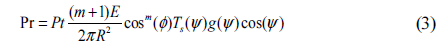
Here
IV. EXPERIMENTS AND PERFORMANCE ANALYSIS
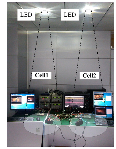
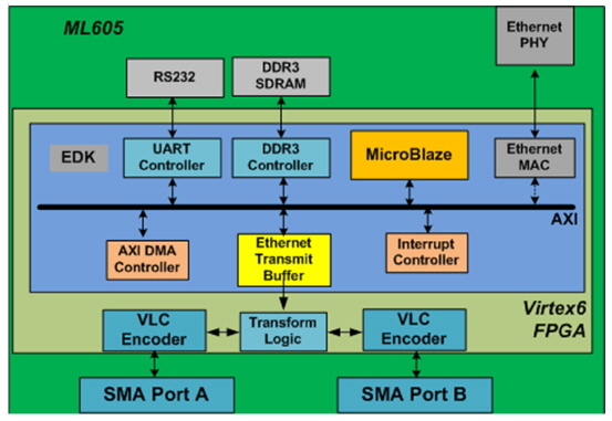
We build an experimental platform and demonstrate the presented mechanism. Figure 5 presents the photo of the experimental platform. The scheduler is implemented by a computer and a Virtex 6 FPGA. The computer is responsible for the user localization, switch control and signaling. It connects to the FPGA for instruction assignment. Outdoor information from a server is connected to the FPGA through the RJ45 Ethernet interface. The FPGA reads out the MAC addresses of the data frames, and accomplishes the service division, VLC modulation, encoding, and distributes them to different LED lamps. At the receiver, the optical signals are received by PDs, and sent to other two FPGAs for being returned back into the Ethernet formats, and at last shown in the user computers. In the platform, two LED lamps (LE_CW_ E2B) and two PDs (Si PIN S6801) are utilized to simulate a two-room house scenario. Infrared LED and corresponding PD are used for uplink transmission and we define associated signaling and switch control messages based on user datagram protocol (UDP). The basic OOK modulation and convolution coding are used. The drive current of the LED is 530 mA, and the active area of the PD is 120 mm2. The LED lamps are deployed at the ceiling while the PDs are put at the table, and the distance between the LED and PD is 1.8 m.
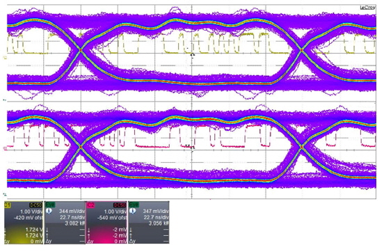
The service division, distribution, modulation and encoding are implemented by the FPGA whose module design is shown in Fig. 6. The scheduler divides the service into two groups, which are transmitted by different LED lamps. Figure 7 presents the waveforms of the two columns of received signals in the two simulated rooms, captured by the
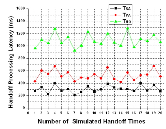
To simulate the presented cross-room switch process in this platform, the uplink infrared LED sends a special message to the scheduler and the switch procedure specified in Fig. 4 is then generated. The software Wireshark operated in the scheduler and the user computers record the exact time for sending/ receiving UDP signaling messages, then the TSA and the whole handoff latency THO can be determined (see Fig. 4). We simulated the switch 20 times randomly and Fig. 8 presents the results. It shows that TSA is less than 400ms and then the radius of the annular switching area is suggested to be

The whole handoff latency THO is less than 1300 ms, which is acceptable in practical cross-room communication considering the existence of the protection area. In the cross-room switch process, the hardware switching and signaling processing latency is less than the time for the human cross-room movement, so the service interruption time is mainly determined by the common speed of human walking. In our experiments, we can see the interruption time TPA is less than 700ms. If the service is a real-time service, the data within this period will be lost, but if it is not a real-time service, a break-point will be set when no general-ACK has been received in the original room and the service will continue to send in the new room without any loss. The experimental platform demonstrates and validates the feasibility of the presented RDM-based VLC network, and the presented mechanisms provide valuable reference for introducing SDM into VLC networks in the future.
In this paper, we present a room division multiplexing mechanism for indoor multi-room VLC network, which utilizes the spatial position of the LED lamp in different rooms as a novel dimension of network resource for multiplexing. The RDM increases the network capacity and makes it possible to introduce SDM into VLC networks in future. In such a network, the service interruption caused by user cross-room movement is an important problem, and we propose a double-area-positioning based cross-room switch solution, along with the LFD-based indoor localization for implementation of RDM. The experimental platform is built to demonstrate the presented mechanisms. The future work is to discuss the feasibility of SDM and associated three-dimensional positioning and handoff mechanisms in more complex indoor VLC networks.