Tunable-focus lens arrays have been reported by many researchers in various fields, such as optoelectronics, optical communications, high-density data storage, cellular-phone cameras, and integral-imaging information processing for various optical applications [1, 2], because controlling the focal length of a lens arrays plays an important role in its active optical performance. Several methods for controlling the radius of curvature of the lens have been proposed to obtain a tunable focusing lens, such as electrowetting, dielectrophoretic, and adaptive liquid microlenses based on isotropic media. On the other hand, it is difficult to tune precisely the curvature of the lenses. Therefore, the tunable-refractive-index method was suggested as an alternative. A range of techniques using the large anisotropy of LCs as another means to a tunable focusing lens have been investigated to fabricate tunable liquid crystal (LC) lens arrays including polymer structure and an LC modulator, such as surface-relief profile, zonepatterned structure, and polymer network LC microlens arrays[3-5]. LC lenses have merits, such as light weight, no mechanical moving parts, and low cost. To adjust the focal length, most LC lenses change the refractive index by controlling the electric field distribution in the cell [3-15].
On the other hand, a complicated special structure is required to realize a continuous-gradient refractive index distribution with an electric field distribution. Moreover, tuning continuously the focal points with an electric field in a curved patterned structure is difficult, owing to the partial distortion of the electric field in a curved structure, which can generate LC deformation. Therefore, it is important to find a more reliable method for a continuously tunable objective distance.
This paper reports the fabrication of an LC lenticular cell with thermally tunable focusing, using the curvature structure of a UV-curable polymer, combined with a TN (twisted nematic) LC cell, along with their optical characteristics. The controllable focal length of the proposed LC lens is based mainly on the difference in refractive index between the curved polymer structure and LC, owing to the different physical properties of the LC molecules according to temperature. Here, in the proposed lenticular LC lens, the temperature can be varied by Joule heating according to the voltage applied to the transparent electrode in the LC lens cell. The TN cell switches a converging to a diverging lens and vice versa.
II. OPERATING PRINCIPLE AND EXPERIMENTAL PREPARATION
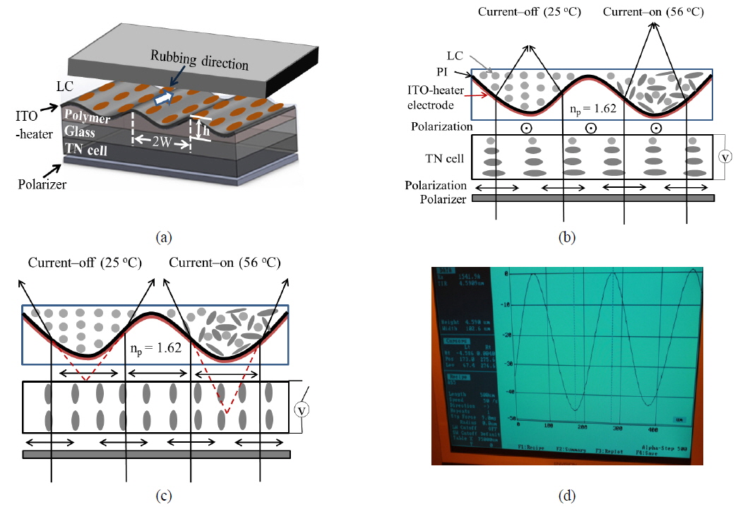
Figure 1 presents a schematic diagram and the operation principles of the proposed lenticular LC lens array and TN cell. As shown in Fig. 1(a), the structure is composed of an indium tin oxide (ITO) electrode deposited on a lenticular polymer array lens,-; an LC layer,-; a polarizer; and a TN cell. Bare glass without an ITO-electrode is used as the top substrate. Figures 1(b) and 1(c) outline the operational principles showing how the proposed LC lens array functions as converging and diverging lenses, respectively, through the “off” and “on” voltage states of the TN cell attached to the polarizer changing the focal length according to the temperature. Based on geometric optics, the focal length f of a microlens can be determined as follows: [16, 17]

where R is the radius of curvature of the lens surface. Supposing spherical curvature, the radius of curvature R of a lenticular LC lens can be approximated as

as shown in Fig. 1(a), where h and W indicate the height and half width of a lenticular lens.
In addition, the refractive indices of the E7 LC were reported to depend on temperature. The temperature-dependent refractive indices of the LC can be expressed by Wu’s model equation as follows [13]:


where γ is a material parameter, Δn(0) = ne(0) - no(0) is the birefringence of the LC at T = 0 K, and Tc is the clearing temperature. Based on Wu’s model of Eqs. (3) and (4), the characteristics of the temperature-dependent refractive indices of the E7 LC have been reported [12-15, 18, 19]. From the experimental result, the values of the constant terms for the temperature-dependent refractive indices are as follows: Δn (0) = 0.3435, γ = 0.1938, α = 1.7432, and β = 5×10⁻⁴ (K-1). The nematic-isotropic transition temperature of the E7 LC is 58°C. In addition, Jun Li et al. examined the wavelength-dependent refractive indices of E7 LC [15]. Our experimental result was evaluated based on the characteristics of the temperature-dependent indices (at a wavelength of 560 nm) of the E7 LC used in this lenticular lens, according to previous experiment result [13, 18].
To manufacture the lenticular lens structure, an ultraviolet (UV) curable-polymer (NOA 1625, Norland Products Inc.) was first spin-coated on a glass substrate at 4000 rpm for 75 s. The polymer layer was then exposed to UV light at 365 nm for 100 s under a lenticular-patterned photomask to fabricate a lenticular lens array. A second UV exposure was carried out for 30 min without a photomask for full curing of the surface lenticular polymer structure. The width 2W and height h of the lenticular polymer lens were approximately 200 and 4.6, respectively. The characteristics of the lenticular lens array produced were observed using an Alpha step, as shown in Fig. 1(d), exhibiting a clear lens image. An ITO heater layer of approximately 70 nm was deposited on the surface of the lenticular lens array by RF magnetron sputtering. The electrical resistivity of the ITO layer deposited on the polymer lens array was approximately 3.5 × 10⁻³ Ωㆍcm. Polyimide (PI), 80 nm in thickness, was spin-coated on the ITO as an LC alignment layer and baked for 5 min at 100°C to remove the solvent, followed by further baking at 200°C for 45 min to induce polymerization. Therefore, the bottom substrate was composed of a transparent ITO heater layer, a lenticular lens array on the glass substrate, and PI. The temperature of the lenticular LC lens cell can be tuned by proper control of the electrical current because the heating material is an ITO conductor with a proper resistance. A glass substrate coated with PI was used as the top substrate. The PI layers of the top and bottom substrates were rubbed parallel to each other to align the LCs.
The materials used were a commercial PI (AL-2001, Nissan Chemical Co.) for the homogeneous alignment and a nematic LC (E7, Merck Chemical Co.). The ordinary and extraordinary refractive indices of the LC were n
In the case of the TN cell, the PI and LC employed were the same materials used for the LC lens array. The PI layers of the top and bottom substrates were rubbed perpendicular to each other to make a 90°-twisted LC structure. The thickness of the TN cell was maintained using 20 -thick glass spacers to satisfy Mauguin’s condition (the limit of slow twist),
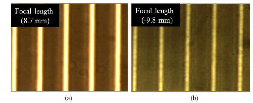
Figure 2 shows the change in the focused-beam image from lenticular LC cells at room temperature (25 °C) with the “off” and “on” states of the TN cell inserted between the polarizer and LC lens cell. These reveal two methods to control the focusing characteristics of the proposed lenticular LC lens array. Figure 2(a) shows an optical microscopy image of a focused beam from the lens cell when the TN cell is in the “off” state. In this case, the polarization direction passing through the TN cell is parallel to the alignment direction of the lenticular LC lens cell. The effective refractive index
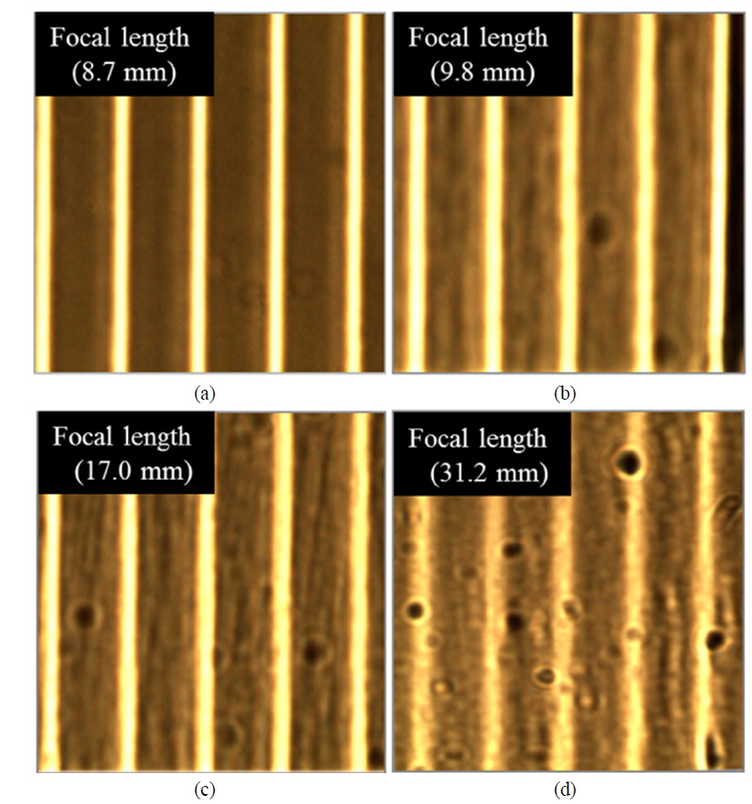
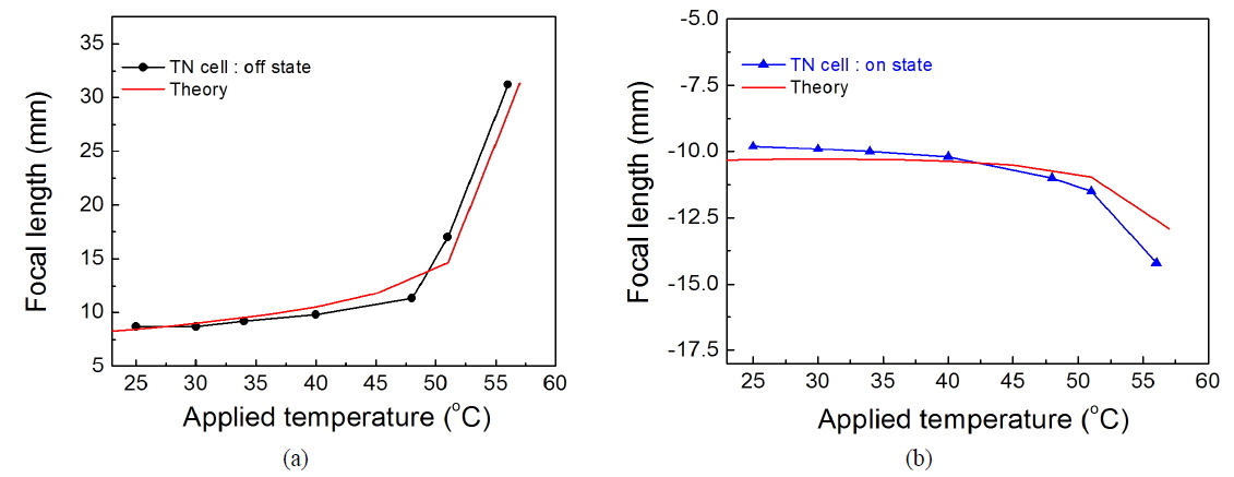
To show an LC lens array acting as a dynamic converging lens, the focal images were observed at different temperatures when the TN cell was in the “off”-state. Figure 3 shows various optical microscope images of the beams focused by the lenticular LC lens at different temperatures controlled by the voltage applied to the transparent electrode in the lenticular LC lens cell. The focal length was varied from 8.7 to 31.2 mm with increasing temperature from 25 to 56°C. These results suggest that the LC lens array functions well as a dynamic converging lens via temperature control.
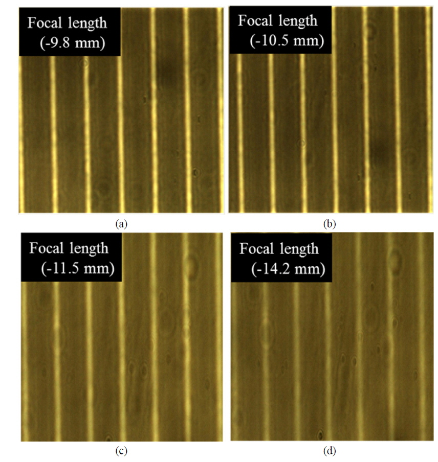
The focal images at different temperatures when the TN cell was in the “on”-state were also observed to illustrate LC lens array acting as a dynamic diverging lens. Figure 4 shows the focusing properties of the beam through the lenticular LC lens cell. As estimated from Eqs. (3) and (4), the focal length of the beam images in the lenticular LC lens cell changed only slightly from -9.8 to -11.5 mm below 51°C but increased in magnitude at normal level for temperature higher than 51°C, reaching -14.2 mm at 56°C. These results also indicate that the LC lens array can function well as a dynamic diverging lens via temperature control.
Finally, to determine the agreement between the experimental and theoretical results for the characteristics of the temperature-dependent focal length of the proposed lenticular LC cell, the experimental focal lengths were compared to the theoretical ones by plotting curves. Figure 5 shows the experimental results and the theoretical values calculated using Eq. (1) with the temperature-dependent refractive indices of E7 LC reported in previous studies [12, 18]. The focal length of the lenticular LC lens was measured by refocusing the dimmed image at each temperature adjusted by Joule heating with an applied vo1tage. As shown in Figs. 5 (a) and (b), the red line indicates the theoretical plot evaluated from Eq. (1) with the refractive indices reported in previous studies according to temperature using Wu’s model. The experimental results showed some agreement with the theoretical values.
A thermally controlled lenticular lens array was produced using a UV-curable curvature polymer structure filled with LC combined with a TN cell, and its optical properties were investigated. The TN cell makes the LC lens function as a diverging or converging lens by electrically controlling the polarization of incident light entering through a polarizer. The focal length of the lenticular LC lens could be tuned continuously by changing the effective refractive index of the LC via Joule heating for each lens type. Consequently, the focal length of the lens with the E7 LC was changed continuously from 8.7 to 31.2 mm for a converging lens type under the “off”-state of the TN cell, and from -9.8 to -14.2 mm for a diverging lens under the “on”-state of the TN cell when the temperature was increased from 25 to 56°C. The proposed LC lens may be limited in efficacy by the surrounding environmental temperature. As an alternative, we could choose a liquid crystal suited to ambient climatic characteristics.