During the last decade, Internet traffic has increased by a factor of 100 due to the exponential growth of end users and the emergence of bandwidth intensive services. It is estimated that this pace will be kept in the near future. To satisfy the traffic demand, networks should be deployed with more transmission and switching equipment with higher capacity, resulting in more PC. Network infrastructures are estimated to account for 12% of the total Internet PC at present, and this portion will increase to 20% by 2020 [1]. Hence, improving the energy efficiency of the Internet becomes a challenging issue nowadays.
With the fast development of optical fibers and other optical components, which have the advantages of huge capacity, low signal attenuation, and high performance stability [2, 3], they are now widely used as the transmitting infrastructure in communication networks. It has been proven that optical equipment is much more energy efficient than its electronic counterparts. Internet protocol over wave-length division multiplexing (IP-over-WDM) is considered to be a promising paradigm for next-generation optical networks with high cost and energy efficiency. IP-over-WDM networks can be implemented in different ways, such as
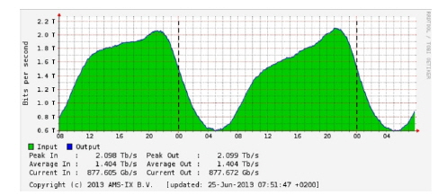
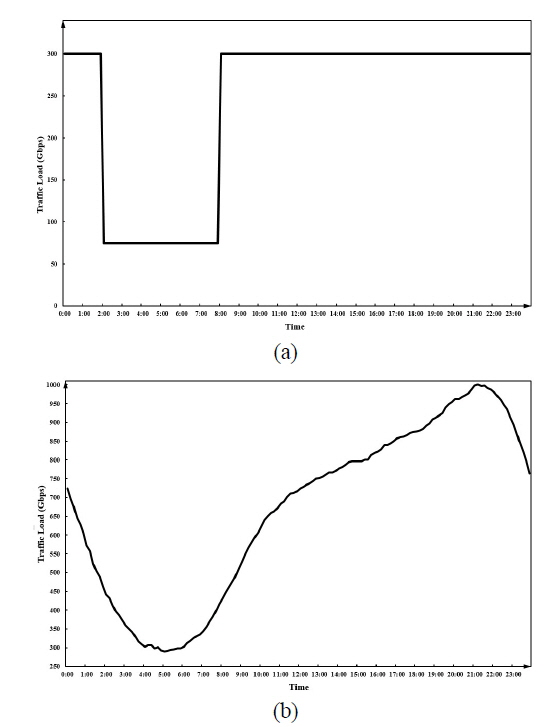
Following the user behavior over different time, Internet traffic presents certain daily patterns that can be approximated with a sinusoidal function [9]. Figure. 1 shows the traffic load for two days (from 8:00 on the 23rd of June, 2013 to 8:00 on the 25th of June, 2013), as monitored by the Amsterdam Internet Exchange (AMS-IX). Peak time occurs around 21:00. Usually a logical topology is designed with capability to accommodate the heaviest network traffic load; hence the network PC is fixed and independent of the traffic load. Considering that a large gap exists between the peak and the trough of the traffic load, a load-adaptive logical topology design (LTD) is expected to be more efficient than a fixed scheme. When the network load is light (e.g. in the late night or early morning), lightpaths can be torn down and the corresponding elements turned off to save energy. On the other hand, when the network load increases, network elements are activated and new lightpaths should be established to accommodate the incremental traffic. This load-adaptive scheme requires that time be divided into multiple periods. Consequently, two important issues should be considered in multiperiod LTD: First, previous load-adaptive methods generally segment time uniformly, and the first period starts from an artificially chosen point [10, 11]. This inflexible segmentation cannot reflect realistic traffic patterns, so the achievable energy efficiency is limited. Therefore, we should determine the optimal time instants at which to reconfigure the logical topology in view of energy savings. Second, the LTR between two adjacent time periods may disrupt data transmission, introducing delay or data loss [12]. When the network resources are optimized to fit the changing traffic load, the quality of service (QoS) in the network may deteriorate; hence, the overhead caused by LTR should remain as low as possible. In this paper, we focus on the multiperiod LTD of IP-over-WDM network. The MILP formulation of optimal time segmentation is proposed, with the objective to minimize the total energy consumption of the network for a given number of periods. In addition, we propose an MILP formulation with the objective to minimize the total network cost, defined by both PC and RO.
The rest of this paper is organized as follows. In Section II, the mathematical formulation for the optimal time division is presented and explained. Section III introduces the mathematical formulation for LTR. In Section IV, illustrative examples are used to evaluate the MILP models, and the numerical results are analyzed. Finally, we conclude the paper in Section V.
II. PROBLEM FORMULATION FOR OPD
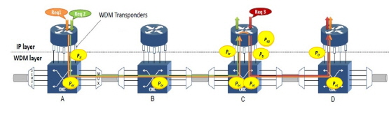
In this paper, we consider the transparent IP-over-WDM network with bypass and traffic grooming. The network architecture is presented in Fig. 2. The IP routers are deployed at network nodes and constitute the IP layer. The function of the IP router is to generate (as a source node), process (as a grooming node), and drop (as a destination node) IP services. The IP router is connected with an optical cross-connect (OXC) via transponders that are used to emit and terminate the lightpaths. Two adjacent OXCs are connected via optical fiber and are responsible for switching the lightpaths. Each optical fiber can support multiple wavelength channels. All of the OXCs and the optical fibers comprise the WDM layer. The IP packets are groomed at the IP layer, and then transmitted directly over the optical WDM channels.
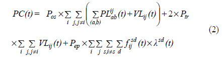
Based on the architecture of the transparent IP-over-WDM with bypass and grooming, the contributors to PC are: (1) IP routers, used to electronically process traffic when traffic grooming is needed; (2) transponders, used to establish lightpaths; and (3) OXCs, used to optically switch wavelengths. The traffic processed at the source and destination nodes is not considered, since it is fixed for a given traffic matrix and does not affect the design of the logical topology. Note that the electronic processing is dependent on the amount of traffic, while the power consumed by optically switching a lightpath is fixed, independent of the amount of traffic traveling on that lightpath. The PC of a transponder is also constant if it is activated, regardless of whether the established lightpath is busy or idle.
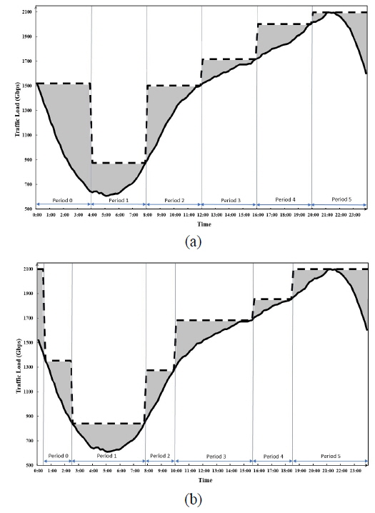
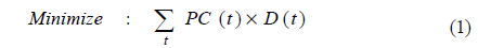
Existing load-adaptive methods used for energy efficient multiperiod LTD usually consider time divisions of equal length, and assume that the first period begins at a specified point (e.g. 0:00 of a certain day, or at the time when the peak load occurs). Figure 3(a) gives an example of equallength division (ELD) when the number of periods (
Inspired by the aforementioned method, we propose an MILP model, named optimal period division (OPD), to minimize the total PC for multiperiod LTD of an IP-over-WDM network. During each period, the lightpaths do not change, and the IP services follow a fixed route; hence the PC of the transponders and the OXCs changes when the LTR occurs, i.e. between adjacent periods. However, the PC of an IP router for electronic processing varies from one step to another, according to the amount of varying traffic load. Based on the notation summarized in Table 1, the MILP model is described as follows:
[TABLE 1.] Notation for OPD model
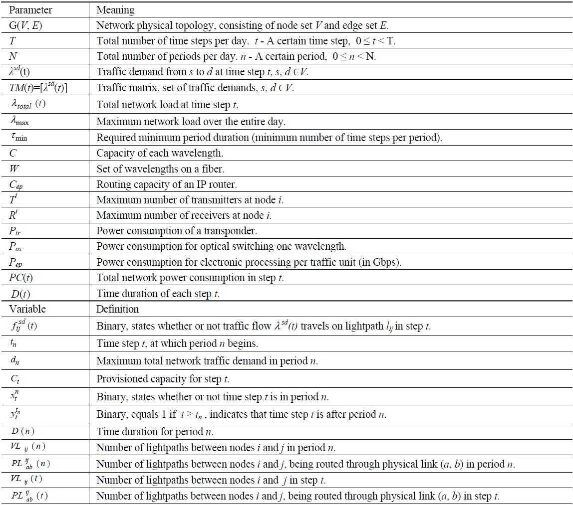
Notation for OPD model

where
subject to the following constraints (constraints that are the same as in Ref. [13] are not shown here):

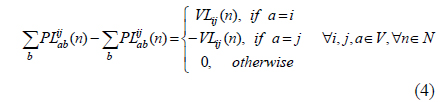
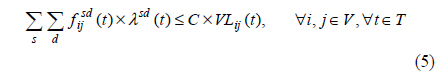


Objective (1) aims to minimize the total energy consumed over the entire day. The PC for each step is calculated by Eq. (2), including the PC of OXCs and transponders in the optical domain and that of routers in the electrical domain of the IP-over-WDM network. Equation (3) and (4) guarantee flow balancing, in view of the traffic flow and the physical links respectively. Constraint (5) limits that the amount of traffic transmitted on all lightpaths cannot exceed the total capacity offered. Constraint (6) guarantees that all traffic electronically processed at a node is restricted by the maximum capacity of the IP router. The numbers of available transmitters and receivers are limited by constraints (7) and (8) respectively. Equation (9) guarantees that the volume of traffic for all source-destination pairs is the total network load. Constraints (3)-(9) need to be satisfied at each step. Equation (10) calculates the duration of one period as the number of steps it contains. Constraint (11) guarantees that the number of physical links used to establish the lightpaths remains fixed for every step in one period. Constraint (12) guarantees that the number of lightpaths remains fixed for every step in one period.
III. PROBLEM FORMULATION FOR LTR
In a multiperiod LTD process, transmission may be interrupted as the traffic needs to be rerouted during the reconfiguration of logical topology. The potential data loss or delay suffered from traffic interruption leads to deterioration of QoS and is viewed as the overhead of LTR, which cannot be neglected. In this paper, the RO is defined as the number of changed physical links between the new logical topology and the previous logical topology. Note that the change in the wavelength assignment is also considered, which means that even if the route of a lightpath traverses the same physical links, a different wavelength assignment is also viewed as a change, and can affect the traversed links.
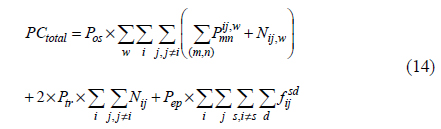
Based on the network assumption mentioned above, we propose an MILP formulation to design the logical topology by considering multiperiod traffic. The physical topology and the corresponding estimated traffic matrix are given in advance. To reflect variations in traffic, one day can be divided into several periods. For each period, the MILP model is run to find the optimal solution with minimal network cost, which contains the PC for the current period and the number of changes in the logical topology from the previous period. The notation used is summarized in Table 2. According to the defined notation, the objective function is:
[TABLE 2.] Notation for LTR model
Notation for LTR model

where


subject to the following constraints:


In the MILP formulation, Equation (13) provides the objective function to minimize the weighted summation of the total network PC and the RO, which are calculated using Eq. (14) and (15) respectively. Since the PC and RO have different dimensions, a weighting factor α is assigned to RO, to make the two factors mutually comparable. Constraints (16)-(21) are similar to those of the previous model. Equation (22) calculates the number of lightpaths between nodes

Another attempt to minimize the RO from previous logical topology, with the objective:

Both of these comparison models can share the same constraints as our model. In the following section, the MILP model with objective (24) is abbreviated “
In this section, the numerical results are presented and analyzed. To evaluate the performance of OPD and
4.1. Network Topology and Parameters
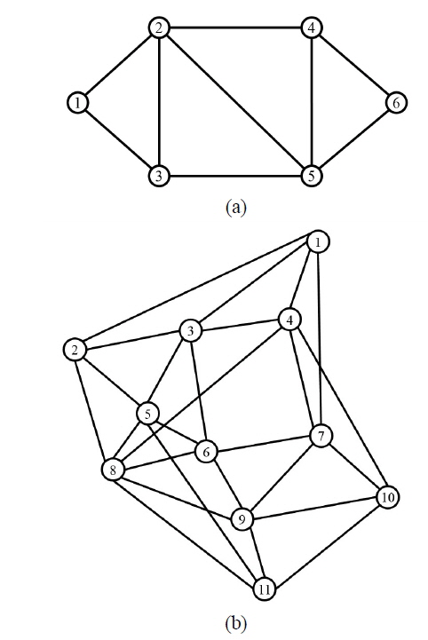
The case studies are implemented for the 6N9L network and the Pan-European COST239 network, shown in Figs. 4(a) and (b). The nodes are connected via bidirectional links, with one fiber in each direction. One fiber can support a maximum of
The PC of the network devices considered is presented in Table 4, which is sourced from the literature and data sheets for commercial products [8, 10, 14]. For the IP router, the Cisco CRS 16-Slot Carrier Routing System is considered. The total routing capacity per chassis is
[TABLE 4.] PC of network devices
PC of network devices
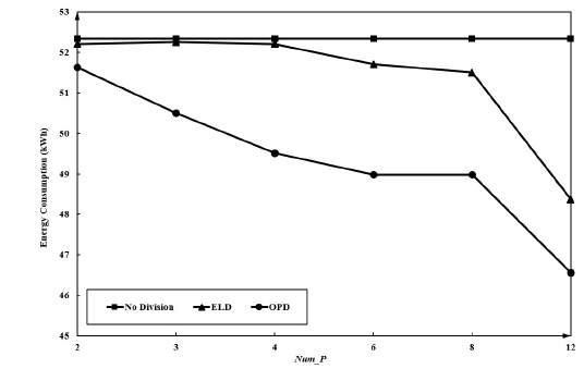
The OPD model is evaluated and compared to the
Table 5 and Fig. 6 show the results for the first and second case studies, respectively. For the first case, the OPD can clearly distinguish between the heavy (300 Gbps) and light (75 Gbps) loads, and find the boundary steps for the two periods. The first period begins when the network enters a light-load state, and this lasts for 3 steps. During this period, some lightpaths are torn down in order to reduce the PC, and low demand traffic flows can be groomed to share wavelength capacity. However, based on the ELD scheme, each period lasts for 6 steps. No matter when the first period begins, the ELD cannot change the logical topology according to the network state. ELD has to provision the heavy load all the time because the light load exists only for 3 steps, while one period for ELD includes 6 steps. Consequently, ELD cannot save any PC, even when there is a large gap between heavy and light loads. In this case, the PC of OPD is only 60% that of ELD. For the second case, OPD can lead to a 2.4% to 10% reduction in PC compared to ELD, according to different
[TABLE 5.] Comparison of EC (Num_P = 2, in kW)

Comparison of EC (Num_P = 2, in kW)
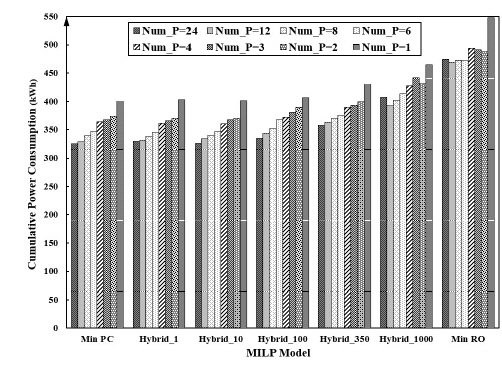
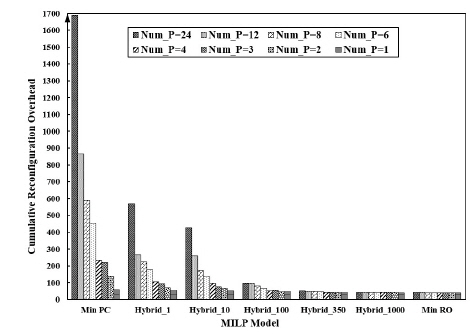
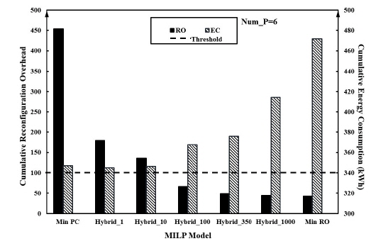
4.3. Results of Hybrid_ α Model
Here we evaluate the performance of the
The numerical results indicate that even though
When network traffic with large variation and burstiness is considered, some network elements can be turned off during a low-load period to effectively reduce the network energy consumption. According to the load-adaptive scheme, the logical topology needs to be designed for multiple periods. In this paper, we proposed two MILP models, OPD and Hybrid_α, to design logical topology of IP-over-WDM networks by considering multiperiod traffic. The performance of the proposed models was evaluated and compared to that of conventional schemes via illustrative case studies. The numerical results showed that the OPD could optimize period delimitation and thereby achieve greater energy reduction, compared to a traditional power efficient method with ELD. In addition, the