Visible light is identified as a viable candidate for indoor wireless communication as it has several attractive advantages over other electromagnetic media [1-3]. In the last decade, visible light communication (VLC) has drawn much interest from many researchers and developers to focus largely on developing and designing a system for a high speed point-to-point communication link. As VLC can provide gigabit class connectivity employing light emitting diodes (LEDs), research is focused on increasing the capacity of the system to attain even higher data rates. However, the performance of VLC systems suffers from finite modulation bandwidth (BW) of the LED and also, as distance increases, light intensity becomes weaker.
To overcome this limitation, a parallel transmission scheme, such as multiple-input multiple-output (MIMO) of radio frequency (RF), has been considered in VLC by many researchers. MIMO is designed to exploit the multipath nature of wireless transmission by deliberately creating a multiple of transmission paths, thus achieving array gain and diversity effect at the receiver, while maintaining the same total transmitted power and bandwidth. Some researchers suggested two transmitters and two receivers optical MIMO using white LEDs [4]. In this system, a pseudo-random bit sequence is converted into two parallel streams prior to transmission. The system consists of two LED arrays, each of which has 1,000 LEDs and does not provide system performance across all positions of the room. Also, it does not facilitate diversity benefits. Recently, 4 × 9 MIMO using vertical cavity surface emitter laser (VCSEL) has been reported [5]. It encompasses 16 QAM and orthogonal frequency-division multiplexing (OFDM) at a distance of 15 m free space transmission link. Although it may achieve extended distance by using the laser, it loses an advantage of illumination plus LED based wireless data communication. In fact, the illumination is one of the most important features of VLC systems. Moreover, it does not extract the diversity effect from the MIMO design, but rather it appears to be 4 parallel SISO links. Due to the use of the lasers, the high performance and longer transmission distance would only be achieved when the receiver is exactly in the line of sight with the transmitter. Other researchers achieved data rates of gigabits/s in VLC with 4 × 9 channel MIMO using OFDM and equalization techniques [6]. This scheme, however, involves a complicated iterative equalization process as well as high level modulation. Some researchers proposed a multiuser color shift keying (MU-CSK) scheme with 3D modulation block using time multiplexing and maximum likelihood estimation method [7]. This scheme, however, does not exploit the diversity effect from their MIMO design.
In this paper, we propose a novel optical RGB MIMO system based on color clusters. The VLC transmission method using color clusters was first proposed for multiuser data transmission by the authors [8]. RGB MIMO refers to a technique by which we can obtain diversity gains through color clustered multiplexing (CCM) from the RGB components of an LED. Thus, data can be transmitted by modulating red, green and blue colors of RGB LEDs separately [8, 9]. At the transmitter, the data bits are divided into 3 parallel sequences to be transmitted from 3 individual color LED arrays and modulated using on-off-keying (OOK). The modulated data stream is then transmitted through individual LED color clusters. At the receiver, an array of photodiodes (PDs) is installed; each equipped with an individual color sensor. As each color sensor will accept only the modulated data from the specified color, there will be no interference from the data modulated using different colors. The received data of each PD in each color receiver is then compared with the data received from the other PDs of the same color receiver. Although various decision schemes would be considered, the present study uses simple selection combining in which the most probable bits are detected. It should be noted that although an equalization process needs to be applied to compensate for channel induced delay, the present work focuses on the multi-cluster MIMO effect and on combining techniques without considering additional benefits from the equalization process.
It is worth noting that the proposed scheme can be viewed as a variant of wavelength-division multiplexing (WDM). The present MIMO transmission is, however, designed to create multiple transmission paths deliberately within a color cluster for the sake of diversity benefit, while WDM multiplexes a number of signals onto a single channel by using different colors of laser light and thus offers no salient feature of diversity [10].
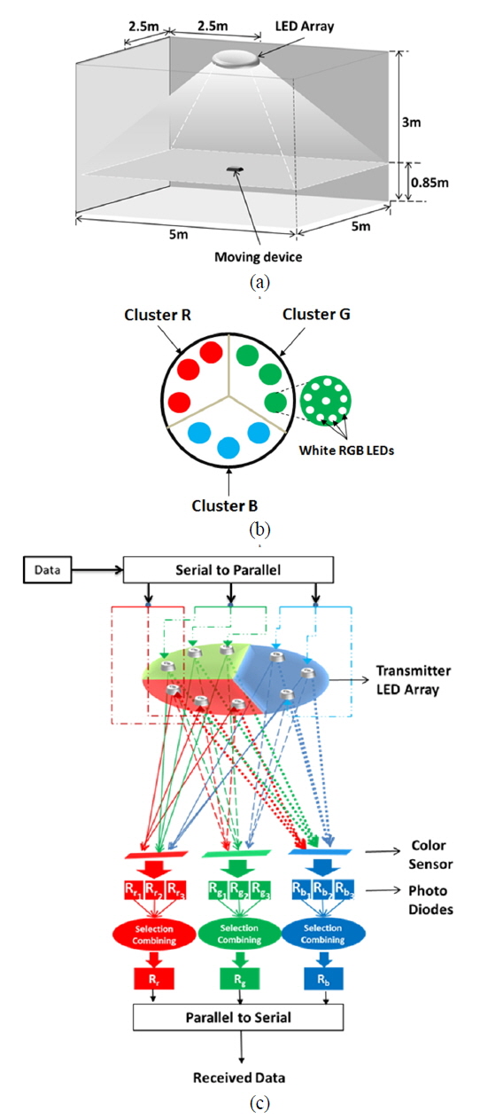
Figure 1(a) illustrates a typical indoor environment for the proposed scheme with room dimension 5 m × 5 m × 3 m (length × width × height). In general, an indoor VLC system should fulfill the illumination functionality besides the provision of wireless data communication. For this purpose, we designed LED arrays that consist of three color clusters of LEDs as shown in Fig 1(b). Please note that all the LEDs shown in Fig. 1(b) are RGB LEDs and the color indicates the cluster color, i.e. the beam used to modulate user data in each color.
[FIG. 1.] (a) Typical VLC indoor environment (b) RGB LED array (c) Proposed optical RGB MIMO system.
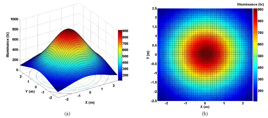
Another important aspect that VLC needs to achieve is to provide proper color and brightness in illumination. To accomplish these objectives, RGB LEDs emitting white light are utilized, thus satisfying the brightness level for indoor illumination mentioned by ISO [1]. Figure 2 shows illumination distribution. It is important to note that only a single beam of color is modulated in each color cluster to carry user data. In a color cluster with RGB LEDs, the average power of one color would vary in that cluster, due to the OOK transmission. To maintain white color illumination, other colors are supplied with DC according to the power variation of one color. This would also help to reduce flickering during transmission.
At the transmitter, an input binary sequence is divided into three parallel streams, one for each color cluster. In each cluster, the data stream is modulated using the OOK modulation scheme. Figure 1(c) depicts the design of the proposed system where each LED in a cluster transmits the same data stream, thereby increasing the diversity gain. At the receiver, the color sensors are used to detect the intensities of each beam. In each cluster, data received using each photo detector is compared with other data received from other photo detectors and selection combining, i.e. the most probable bit among the three candidates, is performed. This scheme contributes to significant improvement in the performance.
The luminance expresses the brightness of an illuminated surface. It is assumed that the light intensity emitted from the source has a cosine dependence on the angle of emission with respect to the normal surface [1]. The luminous intensity at angle

A horizontal illuminance

where

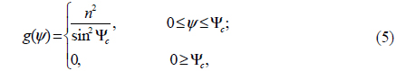
For example, Φ1/2 = 60 degrees corresponds to
[TABLE 1.] System simulation parameters
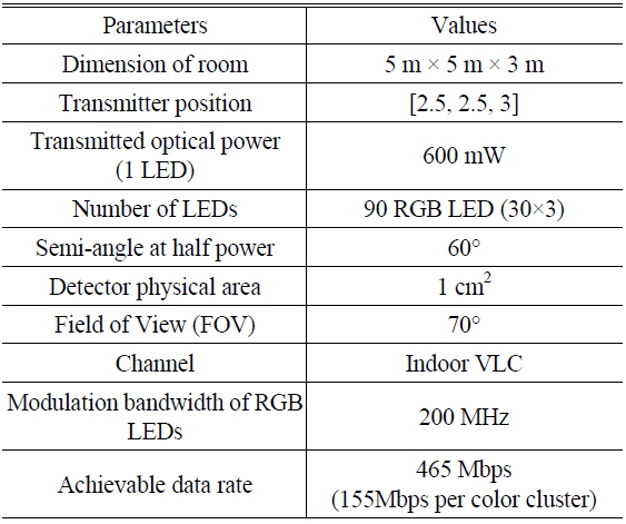
System simulation parameters
Figure 2 shows the illumination distribution results. According to the ISO standard [1], it can be said that the room is sufficiently illuminated across all positions of the room except for the far corners of the room as the analysis shows illuminance of 250 to 900 lx.
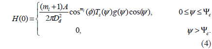
In an optical link, the channel DC gain is given by [1]

where
where
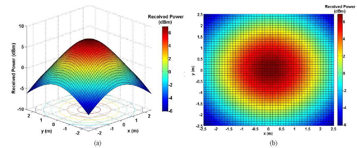
The received optical power

Figure 3 shows the distribution of received power in indoor VLC environment (FIG. 1(a)).
In the RGB MIMO, an input binary sequence is divided into three parallel streams, one for each color cluster. In each cluster, the data stream is modulated using the OOK modulation scheme. At the receiver, the data separation for each color cluster is performed using a color sensor. Each color sensor is able to identify red, green and blue colors individually, and it outputs individual voltages proportional to the intensity of each color. Hence, there is no interference from the data modulated and transmitted using different colors. The performance evaluation was conducted under Additive White Gaussian Noise (AWGN) with the parameters in Table 1.
The optical wireless channel model under AWGN is expressed as

where
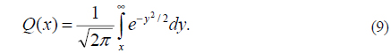
As we consider the OOK modulation scheme, light is transmitted for a bit “1” and no light is transmitted for a bit “0”. A rectangular pulse shape is assumed and its duration equals the bit period [1]. Then, the bit error rate (BER) for OOK modulation is given by

where
As described in the proposed scheme, however, the BER of the proposed scheme,
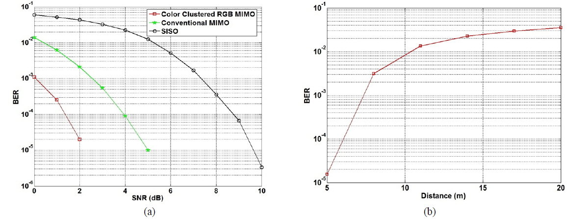
Figure 4(a) shows the MIMO VLC performance comparison between SISO, conventional MIMO [11] and the proposed color clustered RGB MIMO. Here, the conventional MIMO refers to multiple LED arrays at the transmitter side and multiple photodetectors at the receiver side as mentioned in [11]. In [11], BER is calculated by comparing the estimate of the transmitted signals,

where
In addition to the BER performance evaluation, we performed transmission distance evaluation by increasing the distance to the receiving plane. Figure 4(b) shows the BER performance relative to increasing distance with 90 LEDs per color cluster applied. It should be noted that the BER performances of Fig. 4(b) indicate BERs averaged over all positions of the room. The proposed system with 90 LEDs per color cluster offers an average BER of 10-3 over the room at a distance of up to approximately 7.5m. This distance can be further increased with more RGB LEDs per color cluster applied.
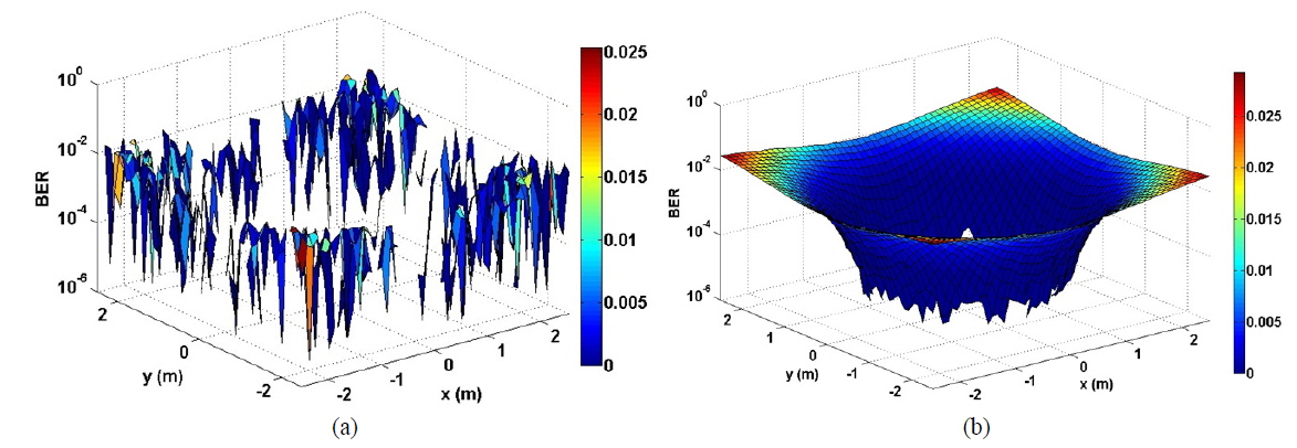
For the whole coverage of a typical indoor room (see Fig. 1(a)), it is interesting to investigate the BER distribution. Figure 5(a) shows the BER distribution of RGB MIMO VLC system under AWGN, whereas Fig. 5(b) illustrates the BER distribution of the same system under static noise.
A novel color clustered optical RGB MIMO system is proposed. As inherent in MIMO, diversity gain and color clustered multiplexing are achieved by utilizing the RGB components of LEDs. By exploiting the property of RGB LEDs, the data are modulated and transmitted separately using red, green and blue colors. The BER performance of the proposed system is found to be superior when compared with both conventional VLC and other MIMO VLC schemes. It is also observed that the transmission distance can readily be increased by adding more RGB LEDs in the proposed system. The results show that the proposed scheme is simple and efficient as high performance and adequate illumination are provided.