Electronic holographic displays require a large number of data points, and a digital micro-mirror device (DMD) has a benefit to be applied for electronic holographic displays due to the modulation speed. In the DMD, each pixel has two stable states, and it can be turned on and off mechanically. Therefore, this is a binary amplitude-only spatial light modulator (SLM) and it is natural that the quality of reconstructed image is worse than that of a gray-scale amplitude-only SLM.
Early research on binary holograms was performed by Brown and Lohmann [1-3]. In these studies, there was some freedom to design the structure of every pixel independently where each pixel presents both amplitude and phase modulations of the optical wave. However, the shape of all pixels in the DMD are the same and there is no room to present complex modulation. But binary amplitude-only modulation has an interesting property. It represents +1 and 0 and it can be understood as a bias-shifted binary phase-only modulation that represents +0.5 and −0.5. In this case, the bias is the DC-term in the Fourier domain. This conversion is an analogy to the optical single side-band filter usually used in electronic holography [4].
There have been remarkable studies to represent a gray-scale amplitude-only hologram [5-7] or a complex hologram [8] by using the DMD. Takaki suggested methods to display a single gray-scale hologram by using a set of several binary holograms. Here, the holograms are sequentially presented with different intensities of the incident wave. On the other hand,. Onural proposed a complex hologram using two binary holograms. One is responsible for the real part and the other is responsible for the imaginary part. In these previous studies, the hologram is decomposed at the SLM plane. However, there is a new way to decompose the hologram in the Fourier domain instead of in the SLM plane. In this paper, we are concerned with the case for which the object plane is positioned at the Fourier domain. In this situation, there is a great advantage for keeping the optical power of incident wave constant. It results from the fact that any point in the Fourier plane is related to all points in the hologram.
In this paper, we propose a new algorithm to decompose a grayscale hologram in the Fourier domain. We find an interesting property of a binary hologram that the quality of the reconstruction image is improved when the spatial frequency bandwidth of the hologram is severely limited. The iterative method has great advantages to increase the diffraction efficiency and regularity of the reconstructed image [9, 10]. In this paper, an iterative segmentation algorithm is applied to generate a set of binary holograms where the segmentation of each hologram is carefully defined. Last, we demonstrate our decomposition method experimentally to prove its feasibility.
II. BAND-LIMITATION OF BINARY HOLOGRAM
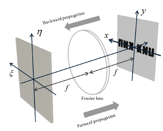
In digital holography, Fourier optics is very useful for optical signal processing. In this paper, we are concerned with the Fourier optic situation where the decomposition is based on the segmentation in the Fourier plane. Figure 1 shows the object wave and the twin wave positioned at Fourier optics. The input plane (
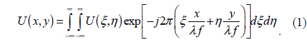
Here,
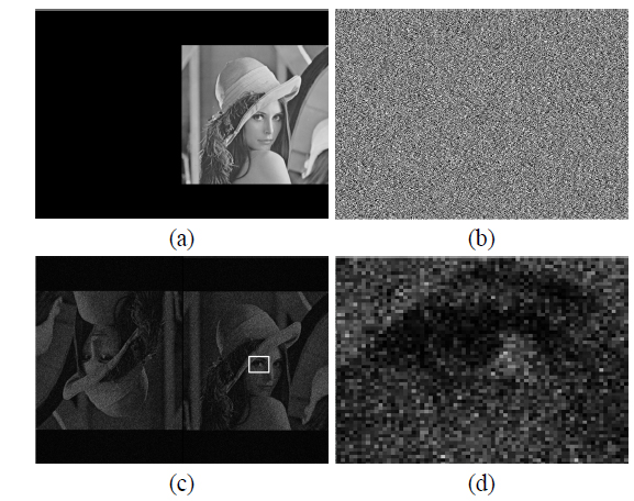
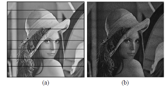
The DMD is also an amplitude-only SLM and it inevitably reconstructs both the object wave and the twin wave simultaneously. The Fourier plane is the best position to separate both of them. For this purpose, the spatial frequency of the object wave needs to be limited within the single-side bandwidth. Figure 2(a) shows a band-limited target image. In this paper, the hologram is computed by iterative Fourier transform algorithm(IFTA). This IFTA is well-known as the algorithm generating the phase-only hologram. In this algorithm, the Fourier optics is proper for generation of the phase-only hologram since the Fourier transform makes any point in the Fourier plane related to all points in the hologram.
There is an obvious reason to apply this IFTA for our purpose. Even though the DMD modulates the amplitude of the wave, it is only binary control. Therefore, when the complex hologram is encoded into the DMD, most of the continuous amplitude information is lost. As previously explained, binary amplitude-only modulation can be converted into the binary phase-only modulation by biasing the DC term in the complex plane. The phase information is significantly different from the amplitude information since the phase is wrapped within 2
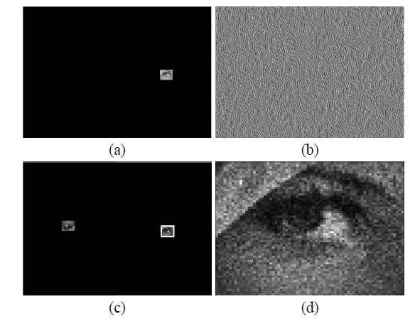
For improvement of the image quality, the band-limitation of the binary hologram in the spatial frequency domain is very effective. Figure 3 shows the case that a target image is only a small portion of the object in the spatial frequency domain. The binary hologram is obtained from the phase-only hologram as shown in Fig. 3(b). The quality of the reconstructed image in Fig. 3(d) is much better than that of the result in Fig. 2(d).
This result is reasonable from the viewpoint of the information theory. The IFTA generates phase-only holograms and the amount of the information decreases abruptly when the holograms are binarized, For example, an 8bit gray-scale image has 128 times more information than that of a binary image. When the bandwidth of the spatial frequency is limited, relatively many pixels are used for reconstructing a point in the spatial frequency domain. Also, the band-limitation means that only a small region in spatial frequency is concerned for reconstruction of the binary hologram and the interference pattern obviously appears in Fig. 3.
III. SEGMENTATION OF TARGET IMAGE
By limiting the spatial-frequency bandwidth of the hologram, the quality of the reconstructed image is improved. Based on this assumption, we propose the way that the target image is divided into several segments and a set of binary holograms for each of the segments is generated based on IFTA. In previous studies [5-8], the optical power of a light source should be differently controlled according to the sub-holograms. In our method, the size of the segments is determined in order that the total intensity of each segment becomes the same. This results in a great advantage that the intensity of incident wave can remain constant. Figure 4 shows the simulation results when the target is vertically divided into eight segments. In Fig. 4(b), only the object part is cropped for simplicity and the resultant reconstructed image looks better than the result from a single hologram in Fig. 2(c).
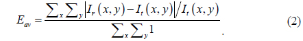
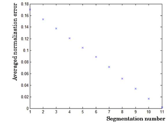
In order to check the effect of the number of the segments, an averaged normalized error is defined by

Here,
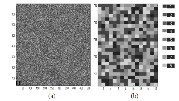
When the target is vertically segmented, the normalized error becomes significantly visible at the boundaries as shown in Fig. 4(b). To avoid this problem, we propose another way to assign the points of target image into sub-holograms. Figure 6 shows a map to assign each point by using a random distribution function. It is helpful to balance the total intensities in charge of each sub-hologram. As previously explained, the total intensities of the sub-hologram are designed to be the same in order to keep the illumination power constant. Therefore, when the target image is segmented, the intensity of each segment needs to be calculated. But when the pixels of the target image are randomly assigned to the sub-segments, the intensity of each segment becomes almost the same.
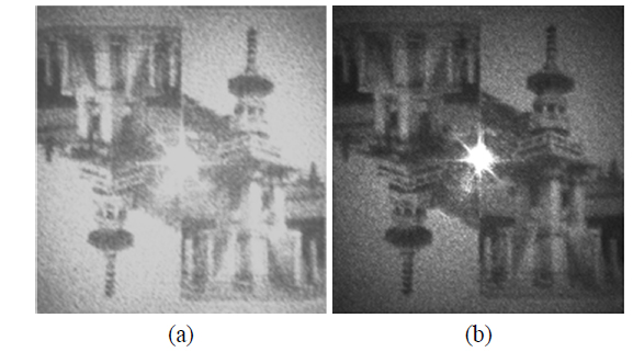
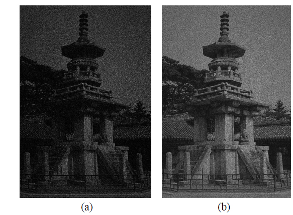
Figure 7 shows the numerical reconstructions from a single binary hologram and from a set of eight binary holograms generated by our segmentation algorithm. Here, the target image is segmented by using the random function. The result from our method presents more details and higher contrast. For example, the fence around the pagoda and traditional roof behind it in Fig. 7(b) look much clearer than those in Fig. 7(a).
To compare the qualities of these results numerically, we introduce a mean square error (MSE) which is defined by
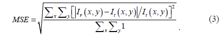
The MSE is expected to represent the irregularity of reconstructed image since it has similar form to the standard deviation. When the image is reconstructed from a single binary hologram, the averaged normalized error is 0.6344 and the MSE is 0.3221. On the other hand, when the image is reconstructed from a set of eight binary holograms, the averaged normalized error becomes 0.5312 and the MSE is 0.2962. We think that this relatively small improvement results from the segmentation using a random distribution function. Even though this random distribution function is used to diminish the distinct error along the boundaries among vertically divided segmentations, ironically the length of boundary of segmentation from the random distribution function is much longer than that of the simply divided segmentation.
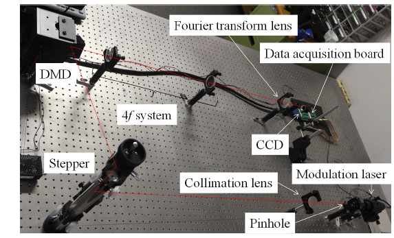
Figure 8 shows the layout of the optical system to demonstrate the feasibility of our decomposition method. A doublet lens with diameter of 50 mm and focal length of 150mm is used as Fourier lens and 4
Figure 9 shows optical reconstruction images from a single binary hologram and from binary holograms generated by our segmentation algorithm. The result from our method has more visibility in detail and higher contrast as expected. Unfortunately, it is not easy to compute the averaged normalized error and the MSE from the captured images. First, the sampling interval of the CCD is different from the interval of the spatial frequency of the hologram by discrete Fourier transform. Second, it is not easy to fairly compare the reconstructed image from a single binary hologram with the reconstructed image from eight binary hologram since the latter is a time-averaged image. It means that the exposure time of the CCD is very critical in the experiment. Therefore, the images in Fig. 9 are a little blurred due to the long exposure time.
Recently, the DMD has received large interest due to its ability to modulate the optical wave by high speed. However, it has an intrinsic disadvantage in the quality of the reconstructed image since it is a binary amplitude-only SLM. To overcome this problem, some methods have been previously suggested where a complex hologram is decomposed into several binary holograms in the hologram plane. In this paper, we propose a new decomposition method based on the segmentation of the hologram in the spatial frequency domain. This has significant benefits that the optical power of illumination wave doesn’t have to be changed. The phase-only hologram for each segment is computed by IFTA and binarized. Generally, when the amplitude-only hologram is binarized, the quality is very sensitive to the binarization criteria. However, our method is very robust in binarization criteria since the phase information is already wrapped. We confirmed the feasibility of our method experimentally.