Carbon fibers (CFs) contain at least 92 wt% carbon and have a unique combination of properties, such as extremely high specific strength, stiffness, heat-resistance, light-weight, and good thermal and electrical conductivities, which enable them to be widely used in advanced composites and aircraft and automobile components [1-8].
CF-reinforced polymer (CFRP) composites are typically produced using a polymer precursor and CFs, which are subjected to several heat treatments while applying tension. CFRP composites have a broad spectrum of engineering applications in areas including aerospace structures, sports equipment, and wind turbines because of their excellent performance characteristics, such as high specific strength, high specific stiffness, and good corrosion resistance [9-14].
The mechanical properties of CFRP composites are mainly governed by the quality of interfacial adhesion between the polymer matrix and the CFs. When load is applied to the composites, it is distributed and transferred through the fiber/matrix interfaces. However, because of their smooth nature and chemical inertness, CFs usually exhibit poor bonding behavior in polymer matrices [15-18]. For a given matrix, the interface between the fiber and the matrix will be controlled by the surface characteristics of the CFs. Consequently, surface treatments of CFs are essential to their practical application in CFRP composites. The various surface treatment methods that may be applied to CFs include wet chemical methods, dry chemical methods, electrochemical methods, plasma methods, and sizing or coating methods [19-23]. The surface treatment procedures mainly add chemical functional groups to the fiber surfaces, which increase the attraction between the fibers and the matrix, resulting in a stronger interfacial adhesion compared to pristine CFs [24-32].
The composite polymer matrices can be classified into thermosetting and thermoplastic resins. Thermosetting resins generally occur in a liquid form and are cured by applying heat or through a chemical reaction or irradiation with infrared light, ultraviolet light, or an electron beam. Once they are cured, the thermosetting resins cannot be reheated or melted into their liquid form. Thermosetting resins are easy to process and laminate. Examples of thermosetting resins used in CFRP composites include cyanate ester resins, epoxy resins, phenolic resins, polyimide resins, and vinyl ester resins [33-43].
In this paper, the surface treatment methods for CFs and sample preparation methods for CF-reinforced thermosetting composites are reviewed in detail. In addition, the mechanical and electrical properties of CF-reinforced thermosetting composites are discussed.
2.1.1. Method I
In this method, several bundles of CFs were added to a reaction flask containing a mixture of concentrated H2SO4/HNO3. The flask was placed in an ultrasonic water bath, operating at 152 W and 47 kHz, and maintained at 60℃ for 2 h. The treated substrate was then placed in a beaker and washed with distilled water until a pH value 7 was reached [44].
2.1.2. Method II
Several bundles of CFs were added to a reaction flask containing concentrated HNO3. The solution was refluxed at 120℃ for 5 h and afterwards the HNO3-oxidized CFs were washed with distilled water until neutral pH was achieved [45].
2.2.1. Method I
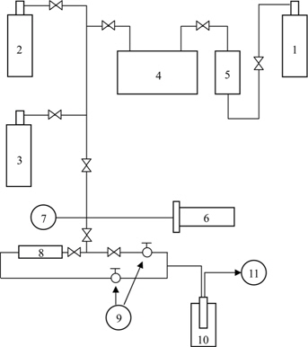
In this dry chemical method, an oxy-fluorination reaction was performed in a batch reactor made of nickel with an outer electric furnace, as shown in Fig. 1. Several bundles of CFs were added to the reactor. After evacuation, fluorine and oxygen mixtures were introduced into the reactor at room temperature and the reactor was subsequently heated to the treatment temperature. After the reaction was completed, the specimens were cooled to room temperature and the reactive gases were purged from the reactor with nitrogen [46,47].
2.2.2. Method II
Several bundles of CFs were heat-treated at 300℃ for 4 h in an inert atmosphere to remove the sizing agents. The CFs were then oxidized in air at 500℃ for 1 h to introduce functional groups onto the surface and to increase the surface area [48].
2.3.1. Method I
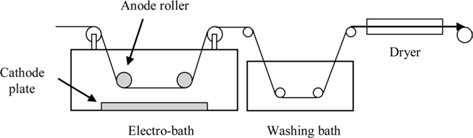
In this approach, the CFs were electrochemically treated using a laboratory pilot-scale apparatus, shown in Fig. 2. The length of the electrolytic treatment bath was 0.23 m. A 5 wt% ammonium carbonate solution was used as the electrolyte and electric current densities in the range of 0-50 A/m2 were used. After anodic oxidation, the anodized CFs were washed with distilled water and rinsed with acetone in a Soxhlet extractor for 2 h to remove any surface impurities or residual oxides [49,50].
2.3.2. Method II
The surfaces of the CFs were treated using a laboratory pilot-scale apparatus. H3PO4 solution (10 wt%) was used as the electrolyte and a constant oxidation rate was used. Electric current densities in the range of 0-1.6 A/m2 were applied. After anodic oxidation, the anodized CFs were washed with distilled water and rinsed with acetone in a Soxhlet extractor for 2 h [51-53].
2.4.1. Method I
In this plasma based method, the reactor was prepared by evacuation, and then a constant pressure of 10 Pa was maintained using argon and oxygen gases. The fibers were mounted on a homemade fixture that could be rotated freely between the electrodes and handled outside the reactor. The fibers were treated at plasma power in the range of 15-150 W in various plasma environments for 10-30 min. At the end of each treatment, the treated fibers were subjected to 30 min of post-treatment under identical conditions [54].
2.4.2. Method II
Atmospheric pressure plasma treatments were performed using dielectric barrier discharges (DBD) operating in air. Two circular copper electrodes were placed in the DBD plasma configuration. Each electrode was covered with a quartz glass plate with a thickness of 2 mm and a circular area that was 210 mm in diameter. The gap between the two quartz glass plates was 6 mm. A pulsed AC power supply with a voltage of 8 kV and frequency of 8 kHz was used. The discharge current and peak pulse current were 40 mA and 300 mA, respectively. The samples were placed on the lower quartz glass plate. Upon discharge, a large number of dense filamentary microdischarges were generated from the upper electrode and the surfaces of the samples were bombarded with the microdischarges [55].
2.5. Sizing or coating methods
2.5.1. Method I
In this coating method, an aqueous solution containing 1 wt% of a silane (used as a coupling agent) was prepared using 50 vol% of methanol, and the pH was adjusted to 4 using acetic acid. The solution was stirred for 2 h. Several bundles of CFs were immersed in the solution for a few minutes and the treated CFs were dried in air at 120℃ for 30 min [56,57].
2.5.2. Method II
Several bundles of CFs were activated in HNO3 for 30 min. Following activation in HNO3, the CFs were sequentially activated in tin chloride and palladium chloride activation solutions. Following this, the CFs were plated with nickel by dipping in a nickel bath. Prior to use, residual chemicals used were removed using Soxhlet extraction by boiling with acetone at 70℃ for 2 h. Finally, the CFs were washed several times with distilled water and dried in a vacuum oven at 120℃ for 12 h [58,59].
3.1. Cyanate ester-based composites
3.1.1. Preparation method I
In this preparation approach, single tow samples were impregnated in a bath containing solvated cyanate ester monomers and then passed through a die to remove the excess resin. The impregnated tow was cut, mounted on a frame, cured sequentially at 170℃ for 1 h and 180℃ for 2 h, and post-cured at 220℃ for 1 h in an air oven [60].
3.1.2. Preparation method II
Impregnated CFs were prepared using a dip-winding technique. A composite layout involving the preparation of 10-ply unidirectional laminates was used for the majority of the mechanical tests. All the laminate samples were cured sequentially at 180℃ for 3 h and post-cured at 220℃ for 1 h in an autoclave [61].
3.1.3. Preparation method III
After pre-polymerization, cyanate esters were cooled and added to acetone. The pre-impregnated CFs were then prepared using a dip-winding technique. When the amount of volatile components reached 5 wt% after drying at room temperature, the prepreg was dried. After that, the prepreg cloth was tailored, stacked, and pressure-molded by following certain regulations. All the laminate samples were cured sequentially at 120℃ for 1 h, 150℃ for 1 h, and 180℃ for 2 h, and post-cured at 220℃ for 1 h in an autoclave [62].
3.2.1. Preparation method I
In this composite preparation method, the desired amounts of epoxy resins and short CFs were mixed at 80℃ for 1 h, and then hardener was added. The resulting mixture was stirred for 30 min followed by sonication for 10 min using an ultrasonicator. The bubble-free ultrasonicated mixture was poured into a preheated mold that was sprayed with a mold-release agent. Curing was performed sequentially at 110℃ for 1 h, 140℃ for 2 h, and 170℃ for 1 h in a convection oven [63].
3.2.2. Preparation method II
Unidirectional composite laminates were prepared by continuous impregnation of CFs using a drum-winding technique for manufacturing prepregs with subsequent hot-pressing. The composites were prepared by filament winding, where the CF roving was continuously soaked in the epoxy matrix bath, before winding on the mandrel. Specimens were prepared from laminates composed of 22 plies and fabricated in a hot-press at 150℃ and 7.4 MPa for 150 min, by a vacuum bagging method used in conventional composite processing [64,65].
3.2.3. Preparation method III
Here, the CFs were placed in the middle of a standard dogbone silicon mold. Both ends of the CFs were stuck to the mold frame to hold them straight along the mold. The epoxy resin was heated and then stirred at a low speed with a hardener. Subsequently, the CFs were brushed with the epoxy/hardener mixture to completely wet them with the polymeric phase and eliminate any possible trapped bubbles. Subsequently, the mixture was poured into the mold and cured at 70℃ for 72 h [66].
3.2.4. Preparation method IV
Composite laminates were produced using the resin transfer molding process. The CFs were placed in the middle of the mold. Epoxy resin was heated and the hardener was added. The resin was then degassed in a vacuum chamber and subsequently injected into the mold with changing pressure. The samples were cured at 70℃ for 4 h and post-cured at 150℃ for 1 h [67].
3.3. Phenolic resin-based composites
3.3.1. Preparation method I
In this composite preparation, CFs and phenolic resin in methanol were mixed and stirred in a beaker at 30℃. Composite plates with a thickness of 2 mm were then prepared and dried in a convection oven at 40℃ to remove methanol. The CF/phenolic resin composites were prepared by stacking 4 plies of plates and isothermally pressing with a hot-press at 150℃ for 30 min [68].
3.3.2. Preparation method II
In this case, the composites were prepared by filament-winding, where the CFs were continuously soaked in a phenolic matrix bath before being wound onto the mandrel. Specimens were prepared from laminates composed of 22 plies and fabricated in a hot-press at 150℃ and 7.4 MPa for 150 min using a vacuum bagging method [59].
3.4. Polyester-based composites
For this approach, polyester resin, accelerator, initiator, and short CFs were mixed and stirred in a beaker. CF/polyester composite samples were prepared by cast-molding between two parallel copper electrodes. The polyester resin was then cured at room temperature for 24 h [69,70].
3.5. Polyimide-based composites
3.5.1. Preparation method I
In this method, powdered polyimide prepolymers were uniformly deposited on CFs using electrostatic powder deposition. Subsequently, dry flexible prepreg was obtained after impregnating the CFs with the prepolymer at 220℃ for 1 min in a heated calendar, which was used to uniformly wet the fibers with the prepolymer melt. The composites were prepared by molding at 0.3 MPa and 330℃ for 1 h, with subsequent post-curing at 350℃ for 5 h [71].
3.5.2. Preparation method II
Prepregging of polyimide was carried out by solvent impregnation of the CFs using a solution of the monomers in methanol. These semi-prepregs were heated up to 220℃ to reduce the methanol and to form a norbornene-endcapped oligoimide. CF/polyimide composites were prepared by molding at 0.3 MPa and 315℃ for 1 h, with subsequent post-curing at 330℃ for 3 h [72].
3.5.3. Preparation method III
Here, a poly(amic acid) solution was first diluted with ethanol. CFs were wound on a frame and impregnated with the solution at room temperature using a layer-by-layer impregnation technique. The pre-impregnated fibers were subsequently dried in a vacuum oven and the dried prepregs were then placed in a preheated leaky mold at 204℃ for 3 min under contact pressure before the application of full pressure (1.75 MPa) for 30 min. The press was cooled to 30℃ before releasing the pressure. The laminates were subsequently post-cured at 290℃ and 0.175 MPa for 4 h and then at 320℃ for 3 h in an air-oven under atmospheric pressure [73].
3.5.4. Preparation method IV
The CF-reinforced polyimide substrates were cleaned with acetone to remove grease or moisture, and then grit-blasted with 46-mesh corundum powders. The pressure of the compressed air used for grit-blasting was 0.4 MPa. To study the influence of preheating specimens were heated in an electric oven to a temperature in the range of 100℃-300℃, and held for 10 min. The samples were coated immediately after removing them from the oven [73].
3.6. Vinyl ester-based composites
3.6.1. Preparation method I
In this ester-based preparation method, 2-butanone peroxide (0.8 wt%) and cobalt naphthenate (accelerator, 0.2 wt%) were added to vinyl ester resin. Then, a vapor-grown CF/resin premixture (33.3 wt%) containing the catalyst was prepared by high-speed mechanical stirring. The remaining catalyst-loaded resin was hand-mixed with the pre-mixture. After placing the CF/vinyl ester mixture for 1 h at room temperature, it was poured into an aluminum mold and the mold was placed on a hot-press. The mold was then removed from the press, placed in an oven at 65.5℃ for 1.5 h, and cooled to room temperature [74].
3.6.2. Preparation method II
The vinyl ester resin was cured by incorporating 2% methyl ethyl ketone peroxide (MEKP, catalyst), 0.3% cobalt naphthenate, and 0.05% 2,4-pentanedione. The above chemicals were mixed with vinyl ester resin and the mixture was poured into a mold. The entrapped air bubbles were removed carefully with a roller and the mold was closed for curing at a temperature of 30℃ for 24 h at a constant pressure of 10 kg/cm2 [75].
3.6.3. Preparation method III
CFs and vinyl ester resin were mixed uniformly using a mechanical stirrer. Approximately 0.3% of cobalt naphthenate was mixed thoroughly in the vinyl ester resin followed by the addition of 2% MEKP, prior to fiber reinforcement. 2,4-pentanedione (0.05 wt%), which is used as a retarder for extending the gel reaction time, was also added. The composite sheets were prepared by the conventional hand-lay-up technique. The entrapped air bubbles were removed carefully with a roller before closing the mould. The castings were subjected to a constant pressure of 10 kg/cm2 for 24 h, to allow proper curing at room temperature [76].
4. Mechanical and Electrical Properties
4.1. Cyanate ester-based composites
Barton et al. [60] prepared CF pre-impregnated tapes from a range of prepolymers containing blends of propenylfunctionalized cyanate ester oligomers and commercial bismaleimide (BMI) monomers. Cured neat resin plaques and CF composites were prepared by autoclave-molding. All the BMI/ cyanate ester blends showed an increase in flexural strength and flexural modulus over the reference homopolymers. When incorporated into a blend, both BMI and cyanate ester showed significant improvements in fracture toughness over their respective homopolymers, owing to the morphological changes within the interpenetrating polymer network resin matrices, which reduced the crosslinking density in the homopolymer matrices.
Ren et al. [61] manufactured epoxy resin-modified bisphenol-A dicyanate (BADCy) and associated CF-reinforced composites. Analyses of their mechanical properties revealed that the flexural strength and impact strength of BADCy could be improved from 95.6 MPa and 9.24 kJ/m2 to 117.8 MPa and 12.6 kJ/m2, respectively, by introducing 5 wt% epoxy resin. Scanning electron microscopy (SEM) images indicated good adhesion between the CFs and BADCy in the composites. Ren et al. [62] also studied the effect of epoxy sizing on the mechanical and morphological properties of CF/cyanate ester composites. Their results indicated that the CFs sized by epoxy resin were able to improve the flexural strength and interlaminar shear strength (ILSS) of the composites. Analyses of the micro-morphology of the fracture surfaces showed reduced flaws in the fiber-matrix interfaces when sized fiber was used.
Chung and Seferis [77] evaluated the thermal degradation of CF/cyanate ester composites. Their results revealed that the interface between the resin and the CFs in the composites was uniform without any visible voids in the matrix. As the composites aged, their glass transition temperature (Tg) decreased dramatically, implying a decrease in the relaxation time.
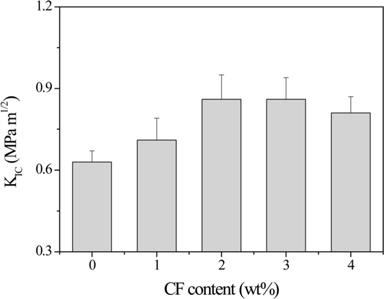
Dong et al. [63] studied the improvement in the fracture toughness of diglycidylether of bisphenol-A (DGEBA) epoxy resins reinforced with short CFs. Their results showed that the fracture toughness of the CF/epoxy composites was significantly improved compared to neat epoxy resin, as shown in Fig. 3. SEM micrographs indicated that a relatively rough surface with shear deformation and tortuous cracks was formed, which prevented deformation and crack propagation and provided higher fracture toughness in the DGEBA/CF composites.
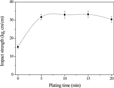
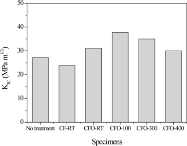
Park et al. [64] proposed a new method based on a nanoscale Ni-P alloy coating on CF surfaces to improve the interfacial properties between the fibers and epoxy matrix in the composites. Their results revealed that the O1s/C1s ratio or nickel and phosphorous amounts increased as the electroless nickel plating process progressed. In addition, ILSS also improved slightly. Further, impact properties were significantly improved in the presence of the Ni-P alloy coating on CF surfaces, thereby increasing the ductility of CF/epoxy composites, as shown in Fig 4. Park et al. [65] also investigated the effect of oxy-fluorination on the physicochemical properties of CF-reinforced epoxy composites. Their results showed that the oxy-fluorination reaction introduced fluorine and oxygen functional groups on the CF surfaces which were more efficient and reactive from the point of view of interfacial reactions with matrix materials. The formation of C-Fx physical bonds between the CFs and fluorine increased the surface polarity of the fibers, resulting in an increase in the mechanical interfacial properties of the CF/epoxy composites (Fig. 5), owing to an improvement in the interfacial adhesion between the fibers and matrix resins. Park and Kim [52] also studied the role played by acidic functional groups on CF surfaces in enhancing the interfacial adhesion of CF/epoxy composites. Their results indicated that oxygen functional groups such as −OH, O−C=O, C=O, and C−O, were attached to the CF surfaces after ozone treatment. The mechanical interfacial properties of ozone-treated CF/epoxy composites were improved compared to those of untreated CF/epoxy composites.
Moaseri et al. [66] introduced a microwave-assisted approach for the functionalization of CFs via aliphatic and aromatic diamines, in order to enhance the interactions between the CFs and epoxy matrix. Their results revealed that the proposed functionalization procedure was able to functionalize the CFs effectively without any discernible structural disruption. The functionalized CFs demonstrated better compatibility with the epoxy resin, leading to considerable improvements in the mechanical properties of the CF/epoxy composites.
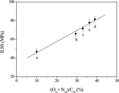
Ryu et al. [49] analyzed the interfacial properties of CF/ epoxy composites. Their results showed that the O1s/C1s and N1s/C1s ratios of the fiber surfaces increased with an increase in the current intensity during electrochemical treatment. The treatment is possibly suitable for incorporating CFs in a polar organic matrix, which would result in an increase in the ILSS of the composites, as shown in Fig. 6.
Siegfried et al. [67] investigated the effect of carbon nanotubes (CNTs) on the impact and residual properties of woven CF/epoxy composites. Their results indicated that the CNTs exert dual effects on the composite properties. While they improved the mode II interlaminar fracture toughness and damage tolerance of the composites, they also make the composites more susceptible to the onset of matrix cracks, leading to a larger delamination area after impact.
4.3. Phenolic resin-based composites
Choi et al. [68] studied the effect of a coupling agent on the electrical and mechanical properties of short CF/phenolic resin composites. The electrical conductivity of the composite was about 10-3-10-1 S/cm. Glutaric dialdehyde, which was used as a coupling agent, was able to improve the mechanical properties of the composite by improving the flow and dispersion of CFs in the matrix and by enhancing the chemical bond between the CFs and phenolic resin during compression molding.
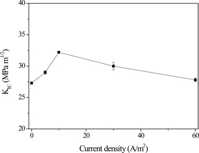
Park and Jang [59] investigated the interfacial characteristics and fracture toughness of CF/phenolic resin composites electrolytically plated with nickel. Their results revealed that the presence of oxygen functional groups and metallic nickel on the fiber surfaces significantly affected the mechanical interfacial behavior of the composites, resulting in increased surface polarity, as shown in Fig. 7. A good correlation between the concentration of the surface oxygen functional groups and the mechanical interfacial properties, and between wettability and KIC, was established, and a current density of 10 A/m2 was found to be the optimum condition for this system.
Li et al. [78] studied the effect of electropolymer sizing of CFs on the mechanical properties of CF/phenolic resin composites. Their results showed that the electropolymer-sized CFs tended to reduce the surface energy, owing to a decrease in dispersion, along with an increase in the polymer film on the CF surface, which plays an important role in improving the mechanical properties of the composites. Compared to the composites reinforced by unsized CFs, the impact strength, flexural strength, and ILSS of the composites reinforced with CFs sized by m-phenylenediamine were improved by 44%, 68%, and 87%, respectively. Similarly, composites reinforced with CFs sized by phenol showed improvements of 66%, 100%, and 112%, whereas those reinforced by CFs sized with acrylic acid showed improvements of 20%, 80%, and 100% for impact strength, flexural strength, and ILSS, respectively.
Marković and Marinković [79] investigated the pyrolysis of CF/phenol-formaldehyde resin composites. Two temperature regions could be distinguished in the pyrolysis of the composites, namely below 770 K, where the CFs held the composite structure, resisting the tendency of the resin to produce composite shrinkage; and above 770 K, where the volume and porosity of the composites abruptly increased, owing to a weakening of the fiber/resin adhesion.
Singh et al. [80] prepared phenolic resin composite sheets filled with a mixture of reduced graphene oxide (RGO), γ-Fe2O3, and CFs. Their results revealed the presence of nanoparticles of γ-Fe2O3 and CF, which gave flexural strength to the composite sheets. Their results also indicated that the nanoparticles of γ-Fe2O3 embedded between the RGO layers enhanced the interfacial polarization and the effective anisotropic energy of the sheets, which contributed to an increase in scattering and led to high shielding effectiveness compared to conventional materials.
4.4. Polyester-based composites
Vilčáková et al. [69] studied the electrical behavior of polyester resins filled with different amounts of short CFs. Percolation of the composites filled with CFs set in at low particle concentrations of 1-2 wt%. For certain filler concentrations above the percolation threshold, the semiconducting characteristics of the composites persisted only at lower temperatures and the composites started exhibiting non-conducting behavior, owing to the switching effect. Only at a somewhat higher CF content of 7 wt%, the composites exhibited clear conducting behavior, irrespective of the structural change of the matrix at the Tg. Vilčáková et al. [70] also investigated the electrical conductivity of polyester resin composites filled with short CFs and confirmed a very low percolation threshold (0.7-0.8 vol% CFs). In contrast to the S-shaped curves calculated according to the percolation theory of composites of globular particles, the dependence between conductivity and fiber content determined experimentally was almost linear, after a steep increase in the percolation region. This atypical behavior was explained by a different mechanism for the formation of fibrous versus globular conducting structures above the percolation threshold. An increase in the scatter of conductivity values observed at the percolation threshold as a consequence of the great fluctuation in the fiber arrangement manifested itself in the conductivity–temperature correlations.
Using optical retardation measurements, Wyatt and Ashbee [81] showed that debonding occurs in polyester thin films containing dispersions of completely embedded CFs. Resin swelling during immersion at 20℃ is insufficient to produce tensile interfacial stress. Untreated glass fibers are still rapidly debonded, whereas CFs retain their interfacial bond. This difference in behavior at low temperatures is attributed to the difference in the chemical nature of the two types of surfaces, i.e., untreated glass fibers are hydrophilic, whereas CFs are hydrophobic.
Sadeghian et al. [82] prepared carbon nanofiber (CNF)-reinforced glass fiber/polyester composites using vacuum assisted resin transfer molding (VARTM). They consistently observed a significant improvement in the critical energy release rates of mode I delamination (GIC), as 1 wt% of CNF was added to toughen the polyester resin. Microscopic pictures showed that the fracture surfaces of the 1 wt% CNF-reinforced polyester/glass fiber composites were more complex than those of regular polyester/glass fiber composites.
Hsiao and Gangireddy [83] investigated the spring-in phenomenon of CNF-glass fiber/polyester composites synthesized using VARTM. Their results showed that the spring-in angles of the L-shaped composites were effectively restrained by the CNFs. An analytical model and a 3D finite element analysis (FEA) model were developed to predict the spring-in phenomenon and to understand the role of CNFs in reducing the spring-in angle.
Srivastava et al. [84] implanted tricalcium phosphatepolyvinyl alcohol-filled CF-reinforced polyester composites into the bone marrow of rabbits. These composites showed a combination of advantageous properties including improved tensile strength, compressive strength, bending strength, and biocompatibility compared to CF-reinforced polyester composites. In addition, CFs showed high modulus and strength for implanted materials without causing any adverse effects. Thus, these materials may prove to be useful for novel applications in the biomedical field.
4.5. Polyimide-based composites
Yudin et al. [71] studied the carbonization behavior of polyimide resins reinforced with CFs. Their results showed that the polyimide resins based on acetyl derivatives of aromatic diamines exhibit low weight loss during carbonization, which makes them promising candidates for use in carbon–carbon composites. The low weight loss exhibited by CF-reinforced polyimide composites was due to strong fiber–matrix interactions, which could result from the cross-linking between the fiber surface and the matrix.
Mascia et al. [72] investigated the structure-property relationships of CF composites based on polyimide/silica ceramers. CF composites produced from ceramer solutions (CF/ceramers) were found to exhibit lower thermal expansion and a greater retention of flexural and interlaminar shear properties at elevated temperatures compared to polyimide-matrix composites (CF/polyimide). CF/ceramer composites were also found to exhibit better thermal oxidative stability at 350℃ compared to the corresponding CF/polyimide composites, although the ceramers with higher silica content developed a substantial amount of porosity.
Liu et al. [73] studied the effect of bond coat on the shear adhesion strength of erosion and thermal resistant coatings on CF-reinforced polyimides. Their results indicated that the substrate was thermally damaged when Ni3Al or copper was deposited as a bond coat, and the bond coat was delaminated from the substrate. Arc-sprayed and plasma-sprayed aluminum and zinc could be used as bond coat materials. In the case of zinc as a bond coat material, the deposition method had little influence on the shear adhesion strength.
Xie et al. [85] improved the adhesion between CFs and polyimides with atmospheric pressure plasma treatment. Their results showed that the oxygen concentration significantly increased after plasma treatment and the oxygen-containing functional groups reached their maximum levels after a treatment time of 32 s. The interfacial shear strength was improved by 21% after plasma treatment for 32 s.
Naganuma et al. [86] investigated the effect of a compliant polyimide nanocoating on the tensile strength of polyacrylonitrile-based CFs. Their results clearly demonstrated that the compliant polyimide nanocoating was effective in improving the tensile strength and Weibull modulus of CFs.
4.6. Vinyl ester-based composites
Xu et al. [74] studied the electrical and mechanical properties of vapor-grown CF/vinyl ester composites. Their results showed that the percolation behavior occurred along with a sharp drop in resistivity at a CF content of 2-3 wt%. Composites made from HNO3-oxidized CFs were insulators even at a CF content of 15 wt%. Incorporating CFs had little influence on the flexural moduli. In addition, it caused a decrease in the flexural strength and increase in the storage moduli.
Kumar et al. [75] investigated the thermo-mechanical properties and erosion performance of short CF-reinforced vinyl ester composites. Composites with 30 wt% CFs exhibited superior thermo-mechanical response along with high energy dissipation/damping ability, in addition to a constant storage modulus without any substantial decay until 60℃. A correlation was observed between the inverse of loss-modulus and erosion rate, which conceptually establishes a possible mechanistic equivalence between erosion and dynamic mechanical loading modes. Kumar et al. [76] also studied the erosion of fiber-reinforced hybrid composites consisting of vinyl ester resin and different weight fractions of short E-glass/CF. The storage moduli of the composites steadily increased up to 3927 MPa, corresponding to 40 wt% of fibers, which may be due to the maximum stress-transfer between the fibers and matrix. The Cole-Cole plots of the hybrid composites showed an imperfect semicircle, indicating the heterogeneity of the system and good interfacial adhesion between different hybrid configurations.
Verghese et al. [87] investigated the mechanical and viscoelastic properties of unidirectional CF/vinyl ester composites. The temperature sensitivity of the horizontal logarithmic shift factors (cooperativity) was found to vary with the sizing used to pretreat the CFs. The observed variations in the experimental trends of cooperativity as a function of fiber sizing for the composites were found to deviate significantly from theoretical predictions.
Wonderly et al. [88] compared the mechanical properties of glass fiber and CF-reinforced vinyl ester composites. The CF laminates proved to be mechanically superior under loading conditions, where the strength is mainly fiber-dominated (i.e., under tensile loading and indentation). The ratio of the CF laminate strength to the glass fiber laminate strength for laminates of equal thickness was similar to the ratio of the CF tensile strength to the glass fiber tensile strength. In the case of CF specimens, the failure was more localized and the strength values exhibited more scatter compared to the glass fiber specimens.
In this paper, we have reviewed the various surface treatment methods for CFs. Those surface treatment procedures mainly introduce chemical functional groups onto the fiber surfaces, thereby increasing the attraction between the fiber and polymer matrix. Sample preparation methods for CF-reinforced thermosetting composites are important for achieving uniform dispersion of CFs in the matrix and for increasing the interfacial adhesion between the CFs and the matrix. Furthermore, we have discussed the preparation methods for various types of composites in detail and have also reviewed the mechanical and electrical properties of the composites. Recent studies have focused on the preparation and characterization of CF/CNT/thermosetting ternary composites, in order to significantly improve the comprehensive performance of the resulting composites.

![Schematic diagram of fluorination reactor [46,47]. 1: F2 gas cylinder, 2: N2 gas cylinder, 3: O2 gas cylinder, 4: buffer tank, 5: HF absorber, 6: reactor, 7: pressure gauge, 8: F2 absorber, 9: glass cock, 10: liquid nitrogen, 11: rotary vacuum pump.](http://oak.go.kr/repository/journal/15600/HGTSB6_2015_v16n2_67_f001.jpg)
![Schematic representation of continuous electrolytic surface anodization process [49,50].](http://oak.go.kr/repository/journal/15600/HGTSB6_2015_v16n2_67_f002.jpg)
![Toughness properties expressed in terms of critical stress intensity factor (KIC) as a function of carbon fiber (CF) content for DGEBA/CF composites [48]. DGEBA: diglycidylether of bisphenol-A.](http://oak.go.kr/repository/journal/15600/HGTSB6_2015_v16n2_67_f003.jpg)
![Evolution of impact strength as a function of electroless nickel plating time [49].](http://oak.go.kr/repository/journal/15600/HGTSB6_2015_v16n2_67_f004.jpg)
![Fracture toughness (KIC) of oxy-fluorinated carbon fiber (CF)-reinforced composites [50]. No treatment: 7.02 (pH) and 15 meq/g (acid value), CF-RT: 6.98 and 18.2 meq/g, CFO-RT: 6.95 and 18.5 meq/g, CFO-100: 6.94 and 22.1 meq/g, CFO-300: 6.94 and 20.3 meq/g, CFO-400: 6.95 and 18.4 meq/g.](http://oak.go.kr/repository/journal/15600/HGTSB6_2015_v16n2_67_f005.jpg)
![Interlaminar shear strength (ILSS) of carbon fiber (CF)/epoxy composites as a function of (O1s + N1s)/C1s atomic ratio of CFs [34]. a: 0, b: 10 A/m2, c: 20 A/m2, d: 30 A/m2, e: 50 A/m2 (current density).](http://oak.go.kr/repository/journal/15600/HGTSB6_2015_v16n2_67_f006.jpg)
![Evolution of KIC of carbon fiber/phenolic resin composites with current density [44].](http://oak.go.kr/repository/journal/15600/HGTSB6_2015_v16n2_67_f007.jpg)