Carbon is a fundamental element found in a diverse range of natural structures, and can be obtained through versatile techniques. Carbonaceous structures are employed in a wide range of applications because of their outstanding mechanical, electrical, and thermal properties [1-4]. Over the last few decades, the development of novel carbonaceous structures, such as active carbon [5,6], carbon nanotubes (CNTs) or carbon nanofibers (CNFs) [7-10], carbon spheroids [11], carbon onions [12], fullerenes [13], and glassy carbon [14] have attracted much scientific interest. Among these structures, CNTs are the most relevant because their unique arrangement of carbon atoms produces remarkable properties, such as high aspect ratio, young’s modulus, and conductivity [15-17]. All these properties depend on the production method [18]. The first CNTs were initially synthesized by the arc-discharge method by Ijima in 1991 [19]. Since that discovery, numerous other production methods have been used to synthesize CNTs, including chemical-vapor deposition (CVD) [20-22], laser ablation [23,24], and electrochemical synthesis [25]. However, these production methods are usually difficult to control, highly expensive, non-continuous (batch process), and not scalable for large-scale synthesis [26], and they require a high degree of energy. To accomplish the large-scale production needed for industrial applications, the flame synthesis method can be used, which is a cost-effective process with controlled energy, high growth rate, scalability, and continuity [27,28].
Although this method is well established, it has not been extensively studied as a CNT production technique. Before the introduction of CNTs, carbon black was the most commercially available carbon material synthesized through flame synthesis. The earliest carbonaceous tube-like structures produced through flame synthesis were observed by Singer in 1950 [29]. The essential components for the catalytic CNT synthesis are basically gaseous carbon and a heat source as well as catalysts. Typically, a gaseous mixture of hydrocarbons is supplied at a constant pressure and temperature throughout the reactor; a metal nanoparticle catalyst acts as an interface between the gaseous reactants and solid carbon precursors by lowering the energy constraints for CNT growth [30]. In this method, gaseous hydrocarbons serve as carbon precursors, while the flame provides the high temperature required for the synthesis. Carbon monoxide, methane, ethane, ethene, and acetylene are typically used as inexpensive gaseous carbon sources. The metal catalyst, which provides the reaction sites for carbon, can be introduced into the system in the form of a substrate or aerosol deposition [31-33]. The structural properties of the CNTs can thus be controlled by scaling the temperature, pressure, and heating rate, or by selecting a specific catalyst, solvent, and fuel profile [34].
In comparison to conventional methods, flame synthesis is a rapid process that can be completed in the order of tens of milliseconds [35]. The growth mechanism can vary depending on the carbon precursors, catalysts, and operation parameters. Three major steps are involved in the growth mechanism of the CNTs [36,37]: 1) catalytic deposition of the carbon precursor molecule on the surface of a metal catalyst; 2) diffusion of carbon atoms over the catalyst particle until supersaturation; 3) formation of hollow graphitic tubes. Nanocatalysts ensure better results, as the solubility of carbon precursors onto the catalysts increases with the surface area of the catalysts. A variety of carbon structures can be obtained by altering the operation parameters such as the equivalence ratio (which is the ratio of the oxidizer to the fuel used), flame configuration, etc. [38]. These carbon nanostructures can be used in a variety of applications such hydrogen storage, field-emission displays, nanoelectronics, hydrogen production, and lithium-ion batteries [24,39-46].
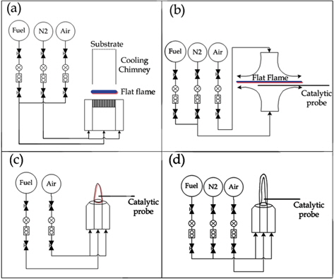
In the flame synthesis process, the type of synthesis is defined as either diffusion or premixed flame synthesis depending on the entrainment of the oxidizer. In diffusion flame synthesis, the oxidizer and fuel combine separately by diffusion; the three possible orientations of the diffusion flames are co-flow diffusion, inverse diffusion, and counter diffusion. When the fuel is introduced through the inner tube and the oxidizer from the outer tube, the orientation is defined as co-flow diffusion; if the positions of the fuel and oxidizer are reversed, this is defined as inverse diffusion. In counter diffusion, the fuel and oxidizer are introduced through different tubes, but their flow directions are different. In premixed flames, as contrasted with diffusion flames, the fuel and oxidizer are mixed before combustion. Fig. 1 shows the schematic representation of the arrangement of these different flame methods [47].
In this review, different flame synthesis techniques are described for a simple and large-scale production of CNTs. Additionally, the effects of various parameters, including flame configuration, catalyst properties, hydrocarbon choice, height and radial effects, are also discussed that may provide relevant information for the optimization of large-scale synthesis.
The formation of tubular carbonaceous structures from flame synthesis was firstly reported by Singer and Grumer, long before the discovery of CNTs by Iijima [19]. However, no evidence of CNT formation was provided in the Singer and Grumer studies because of rudimentary microscopes. A few years later, Saito
According to Saito
As the sampling time increases, the deposition of carbon onto nanotubes and the production rate increase. In addition, dilution with inert gas affects the morphology of CNTs by controlling soot formation [50]. Oxygen plays a vital role in the formation of metal oxides to catalyze the tube formation; however, the excess oxygen may damage CNTs by oxidizing them. Compared to non-coated steel grids, well-aligned and well-graphitized nanotubes can be obtained by using Co-coated steel grids.
The data reported in these aforementioned studies suggest that the supporting substrate controls the morphology and the growth rate of nanostructures due to electronic interactions. In 2000, Vander Wal
In 2002, Merchan-Merchan
Merchan-Merchan
In the same year, Hu
In 2009, Yang
According to the aforementioned studies, it can be inferred that soot formation takes place over a temperature range of 1300- 1600 K. In normal diffusion methods, soot formation occurs at the inner flame region, where the temperature is around 1600 K, and the formation of CNTs takes place in the sooting zone of the diffusion flame. Therefore, the inverse-diffusion method, where the oxidizer is in the center and fuel is outside, was used for CNT production [59-62]. Lee
Nanotubes and nanofibers form in the range of 800℃-1300℃. Nanofibers are dominant in the range of 800℃-1000℃, while the 1000℃-1300℃ range is suitable for multi-walled nanotube synthesis. Xu
The effects of fuel type on the formation mechanism were studied by Camacho and Choudhuri [64]. They reported that thin MWCNTs as well as nanorods and nanofibers can be produced by using methane, while only nanotubes were obtained when using propane. In addition, acetylene-fuel flames produced helically coiled and twisted nanotubes.
As stated above, the growth rate of CNTs or CNFs depends on the height of the burner [65], i.e., as the height above the burner increases, the growth rate decreases due to the decreasing temperature at higher locations, which suppresses the catalyst deactivation. In addition, as the height increases, the CO concentration decreases; this is the main factor responsible for the carbon precipitation. Manciu
According to Hou
Chung and Lin [69] studied the collective effects of acoustic excitation and N2 dilution on the synthesis of nanostructures. They found a uniform radial expansion of heat and adequate distribution carbon precursors in the flame due to acoustic excitation, which leads to an increased synthesis area.
Based on these properties, flame synthesis offers several advantages, as reported by Dhand
In a premixed flame, the fuel and oxidizer are mixed completely before ignition. Premixed flame synthesis methods have certain advantages over the diffusion flame method, including the availability of a broad range of fuels, continuous and multistaged processing, scalability of stoichiometry of reagent gases, flame temperature (can be reduced by using chimneys), reactive gas profile, and equivalent ratio [72].
A number of studies have been published on CNT formation through premixed flame synthesis. Initially, Howard
Such highly spherical fullerenic structures were formed due to the less energetic conditions of the hydrocarbon flames. Additionally, the yield of these structures is significantly lower (~10%) than those obtained with the arc-discharge method (~0%-75%); similarly, the observed aspect ratio of flame-generated CNTs is lower than that of the arc-discharge generated CNTs. This confirms that the flame synthesis is a simpler/better approach for the production of CNTs.
Duan and McKinnon [75] also synthesized CNTs by premixing benzene and air in a low pressure range, finding that the generated CNTs were MWCNTs with open and closed ends, resulting from the complex environment of the flames, i.e., O2 and CO2 in the flame reacted with the carbon on the cap, opening it. A new type of nanocluster with non-hollow cores, consisting of a series of concentric tubes, was also obtained; these were considered to be hydrocarbon crystals. It was proved that the formation of fullerene or graphitic onions is more favorable than that of nanotubes [76]. However, unlike the arc-discharge method, where high pressure supports CNT growth and low gas pressure supports fullerene synthesis, both fullerene and CNTs can be produced in flame synthesis in large quantity under the same conditions.
To satisfy the massive demand for SWCNTs, a cost-effective and large-scale synthesis method was reported based on the sooting flames of premixed various hydrocarbon fuels (acetylene, ethylene, benzene) and oxygen by adding metallocene. This cannot be achieved with the arc-discharge or laser-ablation methods [77]. It was found that acetylene and ethylene fuels contained SWCNTs with few MWCNTs, while in the presence of benzene, only MWCNTs with many defects, sporadic metal filling, and lengths of more than 10 μm were observed. The reason behind this is the rapid breaking of most of the benzene rings into acetylenic units during combustion. As mentioned earlier, soot formation occurs through PAH intermediates, which initially form a single aromatic ring i.e., benzene ring. Unlike acetylene and ethylene, benzene already contains a ring; therefore soot formation occurs earlier in benzene flames. Thus, soot formation starts when the metal particles have not sufficiently grown to catalyze the formation of SWCNTs. This flame technique favors the industrial-scale synthesis of SWCNTs over conventional methods.
Although several studies had earlier confirmed that flame synthesis was a cost-effective, large-scale continuous and scalable method for the production of high-purity CNTs, a systematic investigation of the parameters that affect CNT production was still to be done. Subsequently, Vander Wal et al. [52,78-84] conducted some detailed studies of CNTs synthesis in premixed hydrocarbon flames. In their studies, a McKenna burner was used with a stainless steel chimney at the top of the central fuel tube to stabilize the pyrolysis steam and collect the yield. Various hydrocarbon fuels (e.g., methane, ethane, propane, ethylene, and acetylene) with different metallic additives (e.g., cobaltocene, nickelocene, cobalt acetylacetonate, and ferrocene) were used by varying the flame equivalence ratios. In their setup, metallocene vapors were introduced within the inert gas (which was the main part of the pyrolysis flame), while the fuel-rich premixed flame was located in the outer part of the burner. The results of the study suggested that only the central flame that contained the cyclopentadienyl moieties of metallocene was not the main carbon source; instead, it synergistically supported the CNT growth with the hydrocarbon fuels [78].
As catalyst particles in aerosol form are necessary for flame synthesis, Vander Wal and co-workers investigated different approaches to introduce them into the flames. In one report, a nebulization technique was used to create an aerosol of liquid droplets containing the catalyst (a metal nitrate or ferrofluid) in soluble form, after drying these particles introduced within inert gas or CO [79]. It was observed that the particle size obtained by this method was controlled and uniform, which is favorable for producing uniform SWCNTs. Similarly, SWCNTs were synthesized within the pyrolysis flame using sublimed ferrocene as a metal catalyst precursor [80]; the sublimation temperature was controlled via the mass introduction rate by adjusting the height of the sample holder within the burner central fuel tube.
In another study, a filter paper was loaded with an iron nitrate solution and burned to create an aerosol of the catalyst particles [84]; this was then introduced into the fuel-rich region. In other studies, substrate-supported catalyst methods were used [72,81,84]. The substrate can also interact physically or chemically with the catalyst particles and may control their catalytic activity.
More recently, Height
Notably, several computational and experimental studies have been performed to achieve a deeper understanding of the controlling parameters and growth mechanisms for premixed flame synthesis [36,56,65,86-90]. On the basis of the above discussion, it can be concluded that the premixed flame synthesis of CNTs has several advantages over diffusion flame synthesis. In particular, the flame environment plays a vital role; its chemical and thermal profiles can be easily altered by varying the fuel-air equivalence ratio or by introducing/eliminating the gases that evade the varying gas-phase composition generated by the hydrocarbon pyrolysis processes. Moreover, this method is scalable, and a uniform temperature can be attained across the burner surface; this helps avoid steep spatial gradients in the temperature or species. Unlike the diffusion technique, the premixed flame synthesis is not complex and flame composition can be understood through thermodynamic equilibrium computational algorithms. This method favors rapid combustion and supports manageable flame for laboratory investigations. These benefits provide the basic understanding and potential scalability of the CNT synthesis. However, safety is still a major issue, as there is a constant probability of detonation.
It should thus be mentioned that both techniques present advantages and drawbacks; for instance, the diffusion method is less scalable, but the safety of the premixed flame method is of concern. Therefore, it is hard to establish which of the two techniques is the best. Nevertheless, both the methods enable the fast and large-scale production of CNTs and can be altered by controlling various critical parameters.
In particular, the height of the flame controls the morphology and the structures of the carbon material; the equivalence ratio plays an important role in the production yield, and large-scale production can be achieved by optimizing this parameter. Typically, investigations related to the equivalence ratio are performed on premixed flame as it possesses equal equivalence ratio throughout the flame. It was found that the diameter, length, and yield decrease as the equivalence ratio increases. The residence time is directly proportional to the growth rate. The temperature also has a significant role in the CNT growth. In particular, temperature and the availability of carbon precursors change with location in the flame; consequently, the growth mechanism changes. Acetylene and CO are the leading precursors which support the growth of CNTs. Various transition metals are used to catalyze the CNT growth; the mechanism varies depending on the catalyst properties, such as particle size, melting points, etc.
Suffice to say, numerous flame synthesis configurations can be used to synthesize CNTs in a cost-efficient and energy- efficient way. Moreover, by altering the operation parameters and conditions, various other carbon structures can also be obtained in addition to CNTs, with different morphologies. Furthermore, this simple method may meet the vast demand for large-scale production of SWCNTs for industrial applications such as energy storage, hydrogen storage, and composites. These various set-ups, configurations, obtained structures and other information are accumulated in Tables 1 and 2 [26].
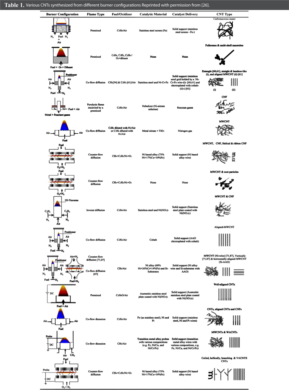
Various CNTs synthesized from different burner configurations Reprinted with permission from [26].
[Table 2.] Different burner configurations and produced SWCNTs Reprinted with permission from [26].
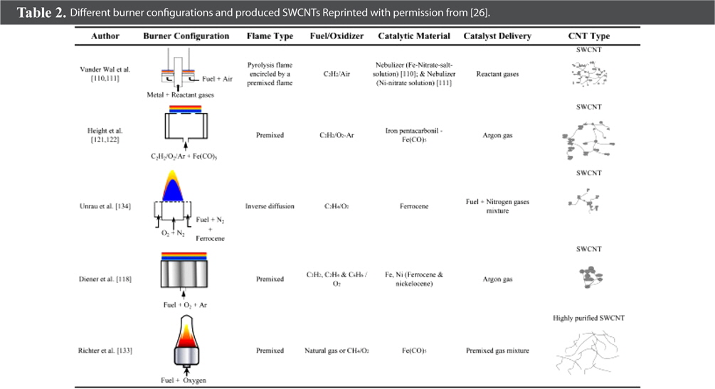
Different burner configurations and produced SWCNTs Reprinted with permission from [26].
This review outlines the economical approaches to large-scale production of CNTs and other carbon structures. Flame synthesis is acknowledged as a low-cost method, as it does not need any complex process or controlled temperature/pressure for its functionality. Several other nanostructures can also be obtained by altering various operating parameters, such as hydrocarbon precursors, burner configurations, additives, catalysts, temperature, distance, and height from the burner, respectively. A much deeper understanding of the factors that influence the synthesis is required for the development of a large-scale production of these flame synthesized nanomaterials, which in future will be used for various commercial applications.

![Schematic representation of the flame synthesis: (a) premixed flame, (b) counter-flow diffusion flame, (c) co-flow diffusion flame, and (d) inverse diffusion flame. Reprinted with permission from [47].](http://oak.go.kr/repository/journal/15585/HGTSB6_2015_v16n1_1_f001.jpg)
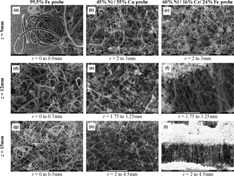
![Field-emission scanning electron microscope images of variation in carbon nanotube morphology corresponding to catalytic probe composition (column) and flame sampling height (row). Reprinted with permission from [60].](http://oak.go.kr/repository/journal/15585/HGTSB6_2015_v16n1_1_f002.jpg)
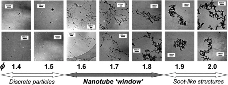
![Morphology variation with equivalence ratio (φ) for samples at 70 mm HAB. Reprinted with permission from [85].](http://oak.go.kr/repository/journal/15585/HGTSB6_2015_v16n1_1_f003.jpg)
![Various CNTs synthesized from different burner configurations Reprinted with permission from [26].](http://oak.go.kr/repository/journal/15585/HGTSB6_2015_v16n1_1_t001.jpg)
![Different burner configurations and produced SWCNTs Reprinted with permission from [26].](http://oak.go.kr/repository/journal/15585/HGTSB6_2015_v16n1_1_t002.jpg)