Electrocardiography (ECG) has been in existence for the past few decades. While the quality of the ECG signal has been extensively researched and the findings exhaustively applied to conventional in-hospital healthcare systems, the comfort of the patient and real-time measurement are usually ignored. An ECG is a test that identifies cardiac abnormalities by measuring the electrical activity generated by the heart as it contracts and relaxes. An ECG is useful in the diagnosis of a range of conditions such as arrhythmias, heart enlargement, inflammations, and coronary diseases [1]. In the event of cardiac arrest, the period between the onset of symptoms and drug administration is about 1 hour [2]. If patients could be treated within the first ten minutes by simply wearing an ECG T-shirt, cardiac damage could be greatly reduced. Moreover, if ubiquitous ECG monitoring of high risk patients was possible, early detection of any abnormalities could be possible and the proper medical precautions could be taken. Hospitals currently use the conventional wet type of ECG monitoring units, which require a long preparation time; also, a gel needs to be used between the electrode and the skin to ensure good electrical conduction. However, the gel causes irritation, allergic reactions, inflammation, and even a good environment to deter bacteria growth during prolonged use. Also, the gel can dehydrate during prolonged use, therefore reducing signal quality. Finally, cross-coupling between neighbouring electrodes may occur through leakage current during long-term use since it is extremely difficult to ensure the adhesives are kept completely separated from each other. Therefore, the wet ECG is not suitable for long-term use. Studies have proven that the continuous sensing of vital signs of high risk cardiovascular disease patients would go a long way to improve the diagnosis and treatment of most of the common cardiac diseases in our world today [3].
Therefore, the goal of this study is to provide more comfort to the user during prolonged ECG measurement and also to provide the user with the possibility of continuing their daily activities while taking vital signs by simply wearing the ECG T-shirt. To achieve this, a non-contact ECG electrode was suggested. Even though dry electrodes (capacitively coupled) also provide comfort to the user by eliminating the problems caused by gels, they still pose the threat of metal poisoning and skin irritation. Therefore, the capacitively coupled electrodes implemented in this work have no direct contact with the skin, although a thin insulator sheet is placed between a metal electrode and the skin.
In this paper, we will discuss the design of our ECG system and the type of sensing method to be employed. The pilot device system will be described and a discussion will be given of the results of the pilot device. Advice for future improvement and the conclusion will then be given.
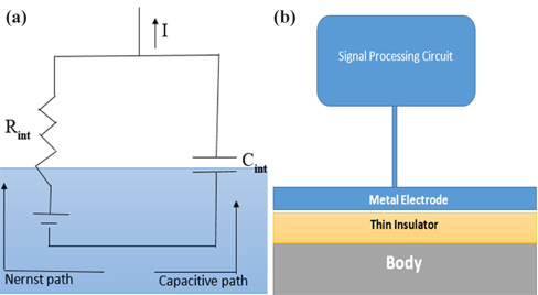
Considering the various types of ECG sensing methods such as resistive and capacitive sensing methods, the capacitive sensing method, a kind of non-contact sensing method, is proving to be a better alternative in providing user comfort than the conventional wet ECG, which uses the resistive sensing method. The capacitive sensing method is implemented using a metal electrode, an insulator, and the patient’s body, which together form a capacitor as shown in Fig. 1(b). The body-electrode electrical model shown in Fig. 1(a) consists of two paths. The path involving the interface potential and the resistor is called the Nernst path. This type of sensing method is known as the resistive sensing method and is employed in wet ECG, whereby a gel enables transfer of charges between the patient’s body and the electrode. The other path is called the capacitive path, in which the transfer of charges occurs through the capacitive coupled electrodes [3]. According to the literature, various insulators such as silicon dioxide [4,5], pyre varnish [6], anodized aluminum [7,8], anodic insulated tantalum oxide [9] or barium titanate [10] have been used as insulators for capacitive coupled electrodes because these materials exhibit high permittivity. In this study, a cotton cloth would be used instead of a rigid material to prevent any irritation, allergy, and discomfort to the user.
Besides being convenient, the advantages of capacitively coupled ECG sensing are that it can be installed in domestic environments that include items such as clothing [11-13], beds [14], and chairs [15,16] and can be configured to communicate through wires or wirelessly with domestic electronic gadgets such a computer, a phone or even monitors. Also, accurate measurement is obtained as the patient might not be aware that his/her vital signs are being recorded.
The disadvantage of capacitively coupled ECG sensing is that the signal quality is not as good as that of wet ECG because of the high impedance of the skin, making the body act as an antenna for noise. Motion artifacts are difficult to eliminate, as any slight displacement of electrodes would change the coupling capacitance, thereby affecting the signal quality.
3. CAPACITIVE COUPLED ECG SENSING SYSTEM
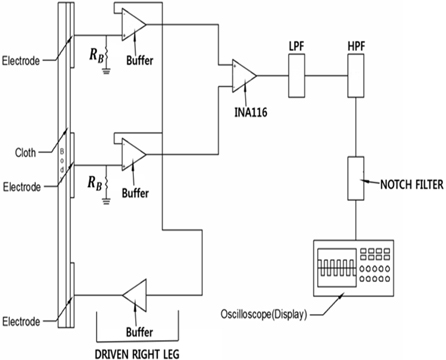
The proposed ECG system architecture shown in Fig. 2 has three electrodes, two of which will be placed on the subject’s chest for biosignal pick-up while the third electrode will be used as a reference electrode and will be placed on the subject’s hip or any other part of the body. The reference electrode would also be used to attenuate common mode noise. An RBias is placed between each electrode and the buffer amplifier as shown in Fig. 2 and shall function as a discharger of DC and of any electrostatic charge developed by the cotton cloth to ground. Very high input impedance buffers are connected between the electrodes and the instrumentation amplifier in order to match the high impedance of the skin. The biosignal obtained from the electrodes is amplified, differentiated, and filtered by the instrumentation amplifier. The amplified differentiated signal is then passed through a low pass filter (LPF), a high pass filter (HPF), and a 60 Hz notch filter to eliminate the unwanted frequency components from the signal. An oscilloscope is then used to display the analogue front-end of the output signal.
Our ECG system consisted of two flexible copper electrodes for biosignal pick-up and a reference electrode for common mode attenuation. LMC6001 was selected amongst other ICs as a buffer amplifier because of its very high input impedance. The biosignal picked up by these electrodes was amplified, differentiated, and filtered by INA116. Since the common mode noise is a major source of noise in capacitive ECG, INA116 was chosen for the system due to its high common mode rejection ratio, low voltage drifts, and low noise. The amplified differentiated signal was then passed through a low pass filter with a corner frequency of 795.8 Hz, a high pass filter with a corner frequency of 0.8 Hz, and a 60 Hz notch filter to eliminate the unwanted frequency components from the signal to obtain an ECG signal range of 0.1 Hz to 100 Hz. A TDS 2024B digital storage oscilloscope was used to show the output signal.
To power up the system, +3.3 and −3.3 biases were provided to the supply of the amplifiers in order to reduce the power consumption of the entire system.
Compared to wet-contact electrodes, capacitive electrodes (a type of noncontact electrode) have a much more complex skin-electrode interface and other processes enter the electrical interaction between the skin and the electrode. Therefore, the effectiveness of the electrode is critical given the small size of an ECG signal (1 mV). Capacitive coupling can be described as a layer of conductive and capacitive structures with a series of RC elements. Both conductance and capacitance are vital for the realization of an effective capacitive electrode. This can be performed by maximizing either the resistance (low conductance) or the capacitance in the skin-electrode interface [17].
To guarantee good capacitive coupling, three key factors were considered: increasing the electrode area, reducing the insulator thickness, and using materials with high dielectric constant. In order to increase the electrode area without compromising the comfort of the user, flexible passive electrodes were employed in this research. Also, a very thin layer of a user-friendly insulator with a high dielectric constant was required to produce a good quality signal. Therefore, several insulators such as wool, cotton, paper, polyester, etc. were considered, of which cotton was chosen because of its superior dielectric constant and user comfort.
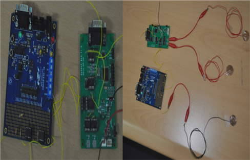
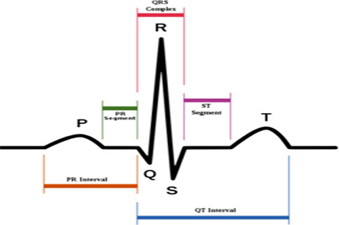
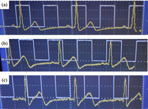
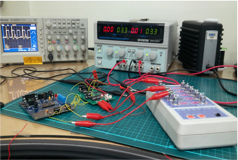
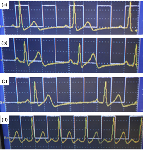
To prove that an ECG device is performing properly, it should be able to display the basic waveform shown in Fig. 4. In other words, the device should display at least three basic peaks, including the P-peak, QRS peak, and T-peak as shown in Fig. 4 because these peaks are vital for the diagnosis of any heart condition. An ECG simulator is a medical device or tool with the appropriate software and the ability to simulate both normal and abnormal ECG waveforms. It is used by medical professionals to assist them in the easy identification of different heart conditions in humans. In this research, an ECG simulator (Techman ES-100) acts as the human body to our pilot ECG device in the first test of device performance. The ECG simulator was used to simulate different forms of 1mV ECG signals such as normal ECG, bradycardia, myocardial infarction, tachycardia, etc. as input signals to the pilot ECG device. Figure 5 shows the connection between an ECG simulator and our pilot ECG system and Fig. 6 shows the output waveform of each simulated input signal. Myocardial infarction (also called cardiac arrest) is caused by insufficient supply of oxygen to the heart muscles due to a blockage of a coronary artery or arteries. With the normal ECG waveform (Fig. 6(a)) as reference, the waveform of the pilot ECG system (Fig. 6(b)) is smaller than the normal ECG waveform due to inefficient conduction of electric potential by muscle cells. Bradycardia (Fig. 6(c)) has large intervals between the QRS peaks. Therefore, a person with bradycardia has a slower heart rate than normal. A person with bradycardia experiences dizziness, weakness, and fatigue. In contrast to bradycardia, in tachycardia, the heart rate is faster than normal. Fig. 6(d) shows the waveform of a tachycardia patient where short intervals exist between the QRS peaks. Our pilot ECG device displayed all three basic ECG peaks as shown in Fig. 4, as well as the waveforms of the different heart conditions.
Since the performance of our ECG system using an ECG simulator has proved successful, electrodes designed from a copper tape were used for further testing of the performance of the pilot ECG system on a human subject. A 24 year old subject already wearing a NIKE Pro combat T-shirt was asked to sit on a chair while electrodes were placed in cotton pockets then integrated into his shirt. The NIKE Pro combat T-shirt was made to be tight so as to deliver adequate pressure on the coupling capacitor. An ECG recording was then taken for noncontact capacitive coupling through the cotton pocket and contact electrode coupling on the dry skin. The result obtained showed three basic peaks and an ECG waveform similar to the normal ECG waveform simulated by the ECG simulator as shown in Fig. 7.
Dry contact and non-contact ECG recordings obtained from a 24 year old subject were comparable to that of normal ECG simulated by an ECG simulator. Also, apart from building a good electronic circuit board for ECG signal processing, another area one must consider with a non-contact ECG is the electrode-skin interface. To obtain excellent signal quality, the electrode contact area, the insulator dielectric constant, the insulator thickness, and the conductivity of the electrode need to be considered. Motion artifacts, however, remains a serious challenge in mobile and wearable ECG systems because they are ill-defined in the literature and are subject to human mobility, unlike other parameters such as gain, power, noise, etc. that can be easily simulated and measured [17]. In this work, matters of motion artifacts have been managed by placing electrodes into a tight NIKE Pro combat T-shirt in order to prevent electrode displacement. Several low power electronic components were selected for this work to reduce the power consumption of the entire system. Even though the current device is portable and consumes less power, it is not as small as desired. Therefore, our future work will concentrate on achieving a very small size wireless ECG sensor system for real time vital sign monitoring.