Oil prices continue to climb due to the instability in the Middle East and the higher costs of the deep sea oil fields. The prices of bunker-C oil heavily used to fuel ships have jumped approximately seven fold from 90 dollars a ton in the 1990s to 630 dollars as of December 2012. The navigation expenses of the 13,000
A ship gains propulsion through a rotating propeller, but the residual swirl energy at the back of the propeller does not contribute - hence the loss of energy. The swirl energy will partially be retrieved as a thrust by the rudder when rectifying, but there is still remaining energy that goes to waste. This study aims to develop an ESD that will recover part of the swirl energy lost the propeller slipstream by employing a special rudder. Such an ESD taps into the swirl energy of the propeller slipstream, decreases the viscous loss behind the propeller hub, lowers the eddy or generates additional thrust to enhance the ship’s speed performance. One of the ESDs that recovers the swirl energy from the slipstream is the twisted rudder that uses the incoming flow angles (Kim et al., 2009; Choi et al., 2010). There are also means of attaching a rudder bulb, or an additional device in a hydrofoil (or a fin) on the rudder bulb to retrieve the energy loss (Mori et al., 1984; Ohtagaki et al., 1986; Okamoto et al., 1999; Sohn et al., 1994). Various types of ESDs have been developed since the energy crisis in 1973. Most of the devices are registered patents at home (Patent Numbers 0346512, 0346513, 0520771, 0853983, 0899737, 1010998, 0901391, 0958075, 0903066, 0903067, 0901393, 1185519, 1205355, 1184076, etc.) and abroad. The demand is now to develop strong performing ESDs that do not overlap with the existing patented devices.
This study designed a Z-twisted rudder, a ZB-twisted rudder, and a ZB-F twisted rudder that account for the flow characteristics of a large container ship’s propeller slipstream and have verified the performance through model tests. The second chapter will go over the objective ship and computational method. Chapter three will look into the design concept of the three twisted rudders; and the following chapter evaluates performance with model tests in a towing tank. The viscous flow analysis was done in Fluent version v.13 (Ansys, 2010).
OBJECTIVE SHIP AND COMPUTATIONAL METHOD
The principal particulars of the objective ship and propeller are laid out in Table 1.
[Table 1] Principal particulars of a ship and a propeller.
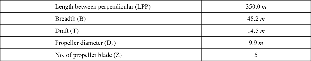
Principal particulars of a ship and a propeller.
The model-ship scale ratio is 45.7613, and FN=0.193, RNM=7.161×10⁶ at ship design speed (VS). FN and RN are non-dimensional values of VS and LPP. And the subscript M and S refer to the model and ship scale, respectively.
The governing equations are the continuity and the Navier-Stokes equations of unsteady turbulent flow. The turbulence model applied is the Reynolds stress model. This study does not go into what the computational method is, the details of which may be found in Choi et al. (2010). The free surface was treated as a double-body model. The computations are carried out at towing and self-propulsion conditions. The sliding-mesh technique was employed to simulate the flow around operating propeller.
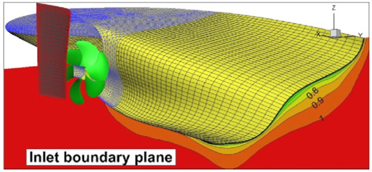
A partial computational domain was used to save computational time. A hybrid grid system that incorporates both structured and unstructured grids was used as seen in Fig. 1.
The grids were generated using Pointwise for structured grids (Pointwise Inc, 2011) and Hypermesh for the unstructured grids. Analysis of the interpretation drawn by altering the inlet boundary plane revealed that St. 3 was the optimal inlet boundary plane. The values of inlet boundary plane were drawn from those of the full computational domain. The time interval was 1° rotation, relaxation factor was 0.2, and a sub-iteration number of 45 were employed. The propellers rotate eight times. The number of grid cells is 3 million. The calculation was done by a 60 core (2.67
THE DESIGN CONCEPT OF THE TWISTED RUDDER
The objective ship is a 13,200
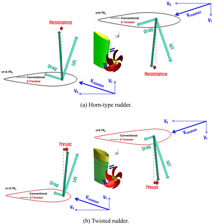
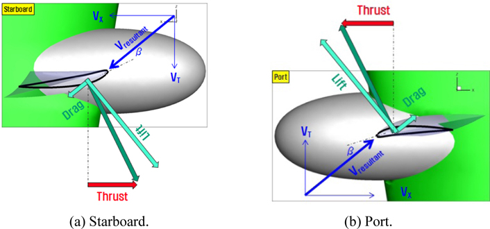
Fig. 3 shows the force diagram applied to the upper and lower planes of the horn-type and twisted rudder, and how the additional thrust is generated. The rotational flow in the slipstream creates opposing incoming flow angles as of the propeller shaft center. The total force in the y-direction due to the lift of the upper and the lower rudder cancel one another, whereas that in the x-direction adds up to increase and acts as thrust. And the total force in the y-direction due to the drag of the upper and the lower rudder also cancel one another, whereas that in the x-direction adds up to increase and acts as resistance. As may be seen in Fig. 3(b), the leading edge of the twisted rudder located above the shaft center is a port, while that of the lower rudder is twisted toward the starboard. Drag and lift of the twisted rudder may be smaller than those of the horn-type rudder, since the angle of attack of the twisted rudder is smaller than that of the horn-type rudder. The twisted rudder reduces unnecessary drag to generate additional thrust, enhancing the propulsive efficiency. This type of rudder also prevents cavitation that often occurs on the gap of the horn-type rudder.
The hub vortex generated on the propeller boss squanders energy. The rudder bulb reduces the loss by weakening the hub vortex and evening out the velocity distribution of incoming flow on the rudder. Theoretically the smaller the gap between the hub cap of the rudder bulb and propeller, the better. The structure and the probability of attachment need to be factored into the practical application. The rudder bulb is recommended not to install together with Propeller Boss Cap Fin (PBCF) that seeks the same objective, i.e., to cut the hub vortex. It is also known that it is not a good fit with the Contra-Rotating Propeller (CRP) on grounds of lack of space.
Fig. 4 shows how additional thrust is created by adding a fin to the rudder bulb. The thrust is generated by tapping into the rotational flow in the propeller stream with the suction side of the rudder starboard’s fin facing toward the bottom and that of the port facing the free surface. The fin is more effective as the rotational and the axial flow of the slipstream is stronger.
DEVELOPING AND EVALUATING THE TWISTED RUDDER
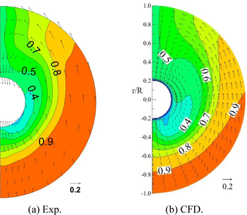
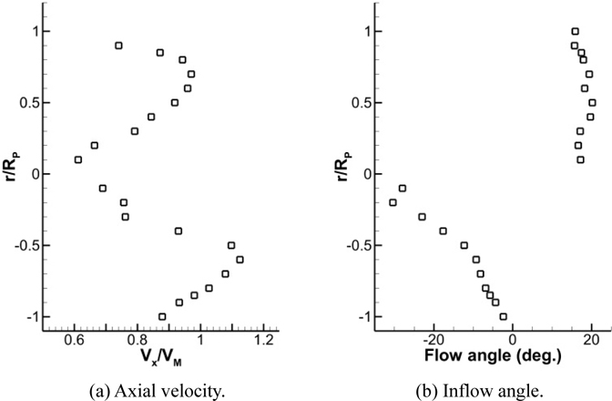
The rudder situated in the propeller slipstream interacts with the hull. Fig. 5 shows the incoming axial velocity to the horntype rudder and the incoming flow angle in the direction of the rudder height in a self-propulsion condition. The axial velocity (VX) is relatively smaller near the propeller shaft center and its maximums are at +/- 0.7RP (RP: propeller radius). The incoming velocity of the lower part is greater than that of the upper part. The incoming flow angle in the upper rudder is nearly constant, but changes in a straight line in the lower part. The Z-twisted rudder is an asymmetry type that has been designed with such incoming flow angles in mind.
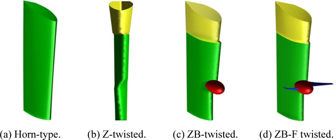
The Z-twisted rudder, the ZB-twisted rudder, and the ZB-F twisted rudder have been designed using a CFD, and have been verified through model tests. Fig. 6 shows the horn-type rudder, and the Z-, ZB- and ZB-F twisted rudders. The upper Z-twisted rudder is slanted toward the port in a certain angle; and the lower part is biased to the starboard from the shaft center; which linearly reduces towards the lower part. Seeing from the front, the lines linking the rudder’s leading edge are in a Z. The center of the rudder bulb is the same as that of the shaft and the propeller hubs. The suction side of the starboard fin faces the bottom, and that of the port fin look to the free surface. The rudder fin’s angle is shaped in a certain twist to incorporate the propeller slip. Note that the fin in port side is longer than that in starboard, since it depends on the strength of rotational flow.
Fig. 7 shows the limiting streamline and pressure coefficient of the horn-type and Z-twisted rudders. The pressure coefficient is non-dimensional value of ρ and VM. In the case of the horn-type rudder, the minimal pressure distribution is narrowly found on the leading edge of the suction side. In the case of the Z-twisted rudder, the minimal pressure is widely distributed with larger magnitude around the maximum-thickness region of the rudder of the suction side.
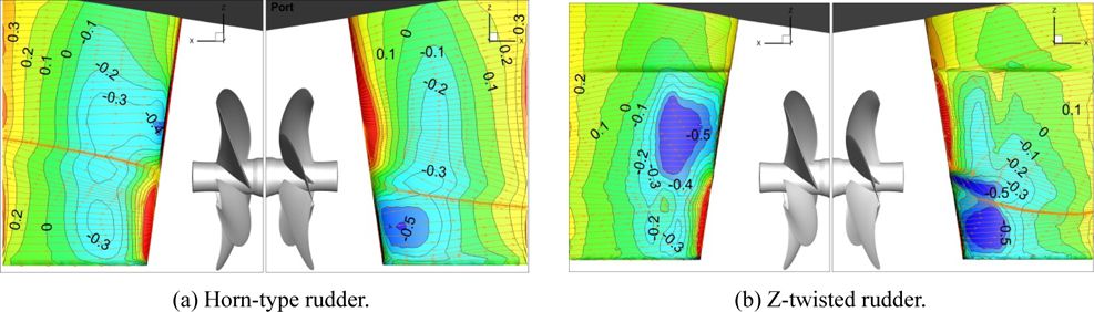
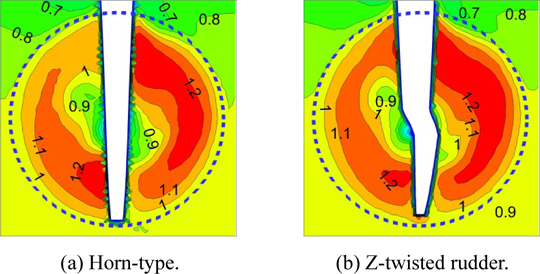
Fig. 8 displays the axial velocity contour at the maximum thickness plane of the horn-type and Z-twisted rudder. The dotted line denotes the rotational surface of the propeller. The flow around the Z-twisted rudder is more accelerated.
A parametric study was undertaken to identify the impact of the twisted angle of the Z-twisted rudder; the rudder bulb’s diameter and length, and the gap between the bulb and propeller hub of the ZB-twisted rudder; and the fin length, shape, and pitch angle of the ZB-F twisted rudder. The objective function is the minimal delivered power (=PDM=2π·nM·QM). The Q is the propeller torque. The calculation is done in the self-propulsion condition of the constant propeller’s rotational speed (nM=8.02 rps). The comparison would have best been taken at the self-propulsion point, but it has been presumed that there is a negligible change in nM due to difference in the twisted rudder’s design parameter. Table 2 offers percentage ratios of the propeller thrust (TM), QM and RVMSP of the model ships with the optimal Z-, ZB-, and ZB-F twisted rudder to those of the horn-type rudder derived from the parametric study. It may be deducted that the twisted rudder pushes down the TM and QM - though the RVMSP does increase - reducing t to cut the delivered power, enhancing speed performance.
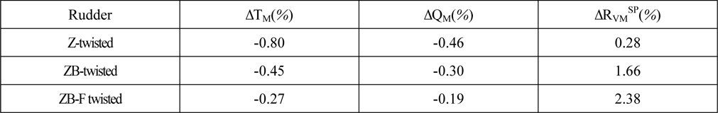
Percentage ratios of thrust, torque and viscous resistance of Z-, ZB- and ZB-F twisted rudder at the condition of nM=8.02 rps.
The model tests to estimate the speed performance with horn-type, Z-, ZB-, and ZB-F twisted rudder were carried out in the towing tank of Hyundai Heavy Industries (HHI). Table 3 displays the results of the self-propulsion tests. All the twisted rudders serve to slightly reduce (decrease) nM, TM, and QM. As a result, the delivered powers of Z-, ZB-, and ZB-F twisted rudder in model scale are reduced by 2.2%, 2.0%, and 2.8%, respectively.
[Table 3] Experimental data of self-propulsion tests.
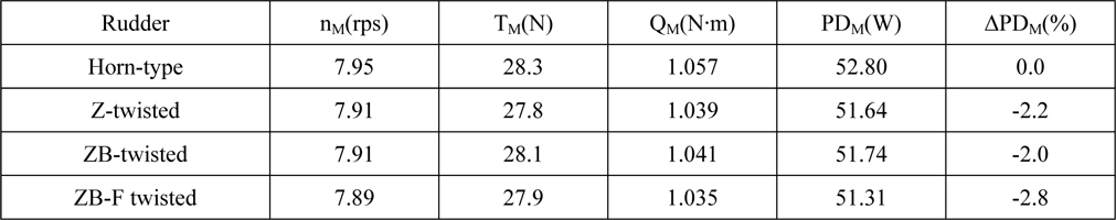
Experimental data of self-propulsion tests.
The speed performance has been deducted utilizing the ITTC-78 model-ship performance analysis method (hereinafter ITTC-78). The scaling of the ITTC-78 ship’s wTS taps into the Sasajima method that separates the potential and the viscous, indicating no scale effect of the potential and reducing that of the viscous by the resistance ratio of the ship and model. The wake due to the rudder is 0.04 which is assumed to be a potential. This study has estimated wTS using a direct method that looks over the scale effect from ESD (i.e., twisted rudder) as seen in Eq. (1).

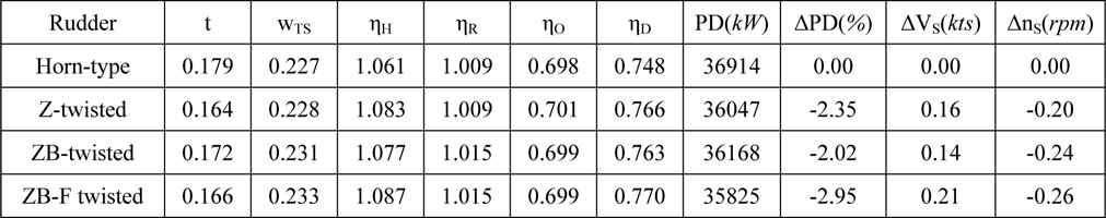
Table 4 relays the self-propulsion factors and the speed performances for the horn-type and twisted rudders.

Self-propulsion factors and speed performances of a ship for the horn-type and twisted rudders.
The main role of the Z-twisted rudder is to lower the t to raise the hull efficiency (ηH). The t drop (8.4%) is because the drag reduces as the incoming-flow angle coincides with the twisted angle as illustrated in Fig. 3. The aim of the rudder bulb is to weaken the hub vortex to reduce the t, but it was not met in this study; and thus requires further research. The rudder fin generates additional thrust to cut the t. There is little difference in wTS due to the twist in the rudder. The rudder bulb and the bulb fin cause the wTS to rise 1.8% and 2.6%, respectively. The hull efficiency (ηH) rises from the reduced t and increased wTS. The relative rotative efficiency (ηR) and the propeller open water efficiency (ηO) do not change materially. Therefore the propulsive efficiency (ηD) is enhanced driven by the increased ηH. In all three rudders, n declines slightly. Accordingly, Z-, ZB-, and ZB-F twisted rudder enhance the speed by 0.16, 0.14, and 0.21
Z-, ZB-, and ZB-F twisted rudders for large container ships were designed with CFD and verified via model tests. The Z-twisted rudder is an asymmetry type that enhances propulsive performance by aligning with the direction of the propeller slipstream to cut the drag on the rudder. The Z-twisted rudder boosted propulsive efficiency by 2.35% by reducing the thrust deduction fraction and raising the hull efficiency. The designing of rudder bulb to reduce the propeller hub vortex did not meet specifications and requires further research. The bulb fin enhanced not only the additional thrust but the effective wake as well to raise propulsive efficiency 2.95%. The research will contribute to strengthening competitiveness in gaining orders by cutting daily fuel oil consumption; increasing sales based on higher performance; and better responding to international environmental regulations by curtailing exhaust gas emissions.