When a ship travels in a rough sea, it frequently experiences various types of impacts from waves. The impact of a ship striking a water surface often causes an extremely large load with high pressure, which shows transient behavior. This can result in substantial damage to the ship's structures. Thus, the water entry problem has attracted much research for its practical importance in the field of naval architecture and ocean engineering (Korobkin, 1996; SNAME, 1993).
The pioneering work on the water impact problem was done by von Karman (1929). His linearized theory was able to calculate the slamming coefficient successfully. However, his theory was not able to estimate the induced free surface elevation. This limitation was improved by Wagner (1932) by taking into account the uprise in the free surface elevation. Mathematical approaches to the water-entry problem were attempted by Garabedian (1953) and Mackie (1969). Similarity solutions for wedges with arbitrary deadrise angle were proposed by Dobrovol'skaya (1969). The solution was expressed in the integral equation form which should be solved by numerical computations.
The solution is applicable for any deadrise angle,
This paper presents a comparison study of experimental data and numerical results. The potential code was developed by the present authors. This potential code was based on the boundary element method (BEM). The commercial code FLUENT was used to solve the water entry problem in terms of viscosity. The present study was carried out under the assumption of a two-dimensional problem. Most theoretical studies pertaining to the water entry impact load involved a two-dimensional analysis of a complicated body geometry (Arai et al., 1994; Faltinsen, 1990; Fraenkel, 1991; Hughes, 1972; Kim and Shin, 2003; Takemoto, 1984; Yamamoto et al., 1984). The two-dimensional assumption sounds like a severe limitation when one considers three-dimensional complex ship geometry. However, a three-dimensional analysis of ship slamming has not yet been realized. Therefore, it is a usual practice to analyze slamming for particular cross sections in ship yards. This means that even a two-dimensional computational tool for water entry problems needs to be developed.
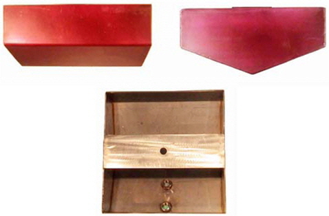
Experimental tests relying on free fall have been carried out to realize the slamming phenomenon (Chuang, 1966). The biggest advantage of the free fall test is the ease with which the desired velocity can be produced. That is to say, a velocity of 1.4 m/s can be achieved by dropping a specimen from a height of 0.1 m, and a velocity of 3.1 m/s can be obtained when the specimen falls from a height of 0.5 m. However, the free fall has several problems. First, a guide line is needed to ensure that the model falls to the free surface as desired. It is difficult to manufacture the guide line system. There might be serious friction in a free fall test when using equipment. Second, the moving distance of the drop test model becomes longer as we increase the velocity, which increases the length of the line between the sensor and amplitude and there is serious noise that makes it difficult to find the peak values of the impact forces. Third, it is difficult to obtain repeatability for the experiments. To overcome these problems, a pneumatic cylinder was introduced (Jung et al., 2002; Jung et al., 2002; Kwon et al., 2003). In other words, we attempted to induce the same velocity as s free fall test by using a pneumatic cylinder. The velocity was measured using a high-speed camera that takes pictures at 500 frames per second. The models were wedge shaped and had three holes in the bottom. The pressures acting on the model were measured separately at the locations of these holes. The pressure time history of the pneumatic cylinder showed a behavior that was different from that of a free fall test. As a result, there was a difference in the peak pressure values.
2. Development of Boundary Element Method Code
Let us describe the boundary value problem to be solved before we discuss the developed potential code. The present paper deals with a two-dimensional analysis. The z-axis takes the positive direction upward. The

The boundary condition on the wetted body surface

where


The new position of the free surface can be obtained by integrating the kinematic boundary condition (3).
On the side wall boundary,

The fundamental solution adopted here is the well-known logarithmic function. Its mathematical expression is

The above integral equation can be solved by dividing the boundary into straight line segments over which the potential values and their derivatives are assumed to be constant. The free surface boundary near the body was densely segmented so that the complex displacement of the boundary could be described. The pressure at any field point in the fluid domain could be calculated from Bernoulli's equation, which includes a nonlinear term

The evaluation was calculated according to Kim and Shin (2003) as follows
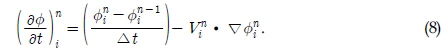
Where represents size of the time step,
The dynamic boundary condition was simplified as follows so that the computed potential values can be robust

Only half of the computational domain was considered due to the symmetry of the present problem. The initial free surface is assumed to be calm. The initial potential values of the free surface were set to zero. To initiate the BEM computation, we need to submerge a small portion of the body.
In the numerical evaluation, the free surface,
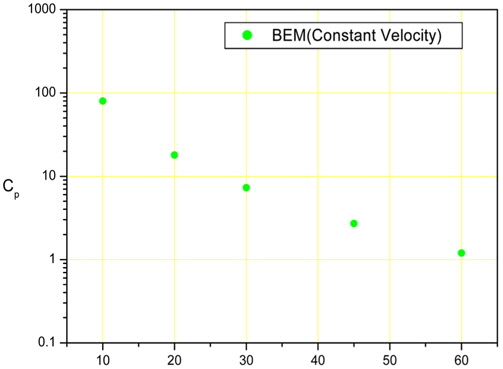
The constant body velocity was set to 1 for all computations. Every scale used in these computations was normalized. The number of meshes on the body, free surface, and wall were 96, 304, and 20, respectively. The time increment for all of the computations was 0.0001 s. The deadrise angles for the wedge models in the calculation were 10, 20, 30, 45 and 60 degrees. Fig. 1 shows the results of the BEM calculations for each case.
3. Application of Commercial Code
The viscous computation for the water entry problem was carried out using the commercial code FLUENT. The computational domain in FLUENT was discretized into a finite number of tetrahedral cells. The movement of the air-liquid interface was traced by the distribution of the volume fraction of the water in a computational cell. The slamming phenomenon was described by forcing a uniform flow to approach the body. The flow was assumed to be laminar. Any readers interested in FLUENT are referred to the FLUENT web site. Dense meshes were distributed near the body and the free surface around the body surface.
In the case of applying a dynamic mesh, FLUENT uses unstructured meshes in order to reduce the amount of time that is spent to generate meshes, simplify the geometry modeling and mesh generation process, model more-complex geometries than a user can handle with conventional, multi-block structured meshes, and let the user adapt the mesh to resolve the flow-field features.
Once we have determined the important features of the problem we want to solve, the basic procedural steps are as shown below.
(1)Create the model geometry and grid. (2)Start the appropriate solver for 2D modeling.(3)Import the grid.(4)Check the grid.(5)Select the solver formulation.(6)Choose the basic equations to be solved: laminar flow is chosen in this computation.(7)Specify material properties: air and water-liquid.(8)Specify the boundary conditions: wall boundary condition.(9)Adjust the solution control parameters.(10)Initialize the flow field.(11)Calculate a solution.(12)Examine the results.(13)Save the results.(14)If necessary, refine the grid or consider revisions to the numerical or physical model.
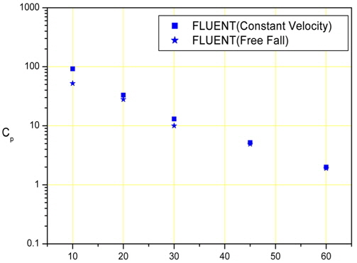
We calculated several model cases. The velocity conditions for the water entry had two cases for each model, constant velocity and variable velocity which took care of the interaction between the body and fluid. The latter seemed to describe the slamming phenomenon more accurately than the constant velocity case. All of the wedge models penetrated a free surface with a water-entry velocity of 1 m/s. the water-entry velocity of 1 m/sec. Fig. 2 shows the results of the FLUENT calculations for each case.
We calculated five different deadrise angle wedge-model cases. These cases were the same as the BEM calculation cases for comparison.
4.1 Equipments for Experiments
4.1.1 Model
The specimen was a wedge-shaped model. The size of this wedge-shaped model was 29 cm (
4.1.2 Pneumatic Cylinder Test
The pneumatic cylinder could be discharged at 3 m/s. This cylinder was produced by SMC in Japan. The inner diameter is 40 mm, and the shooting range is 100 mm. The inner diameter and shooting range are shown in detail in Table 1.
[Table 1] Specifications of instruments for experiment

Specifications of instruments for experiment
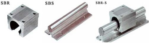
4.1.3 LM-Guide
The LM-GUIDE was introduced to carry out the free fall test in this experimental research. The LM-GUIDE consists of SBR and SBS. There is a ball-bearing at the inner side of the SBR to reduce the frictional resistance between SBR and SBS. The shape of the LM-GUIDE is shown in Fig. 4.
4.1.4 Pressure Gauge and Amplifier
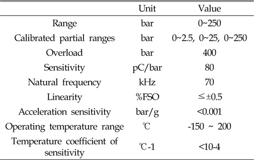
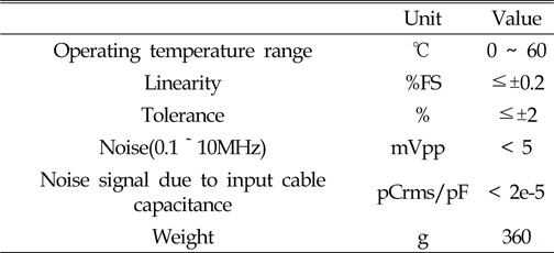
The pressure gauge was made by KISTLER in Switzerland. The model number was 701A. The maximum capacity of the gauge was 250 bar, and it was a piezoelectric type. The natural frequency was 70 kHz. The properties of this pressure gauge are given in Table 2 below. The amplifier was also made by KISTLER in Switzerland. The model number was 5011A, and the specifications are listed in Table 3.
[Table 2] Specifications of pressure gauge

Specifications of pressure gauge
[Table 3] Specifications of amplifier

Specifications of amplifier
4.1.5 A/D Convert
An A/D convert was used to convert the analog signal into a digital signal. The existing data were sampled between 60 kHz and 200 kHz, but we attempted to use a 20-MHz converter to more accurately the water-entry impact. This converter was made by ADLINK Technology in Taiwan (Nudak PCI 9812). We determined that there was no significant difference in the data for rates exceeding 5 kHz. Thus all of the experiments were carried out at 100 kHz. The specifications of the A/D converter are shown in Table 1.
4.1.6 High-speed Camera
A high-speed camera was used to measure the water-entry velocity of the specimens. This was a KODAK SR Ultra-C. The maximum recording rate was 10,000 fps, and total recording time was 1000 fps per 5.5 s. The specifications of this high-speed camera are shown in Table 1.
4.2 Free Fall Test and Pneumatic Cylinder Test
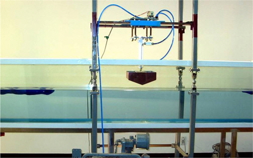
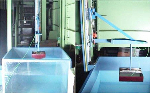
Fig. 5 shows the front view and side view of the equipment set-up for the free fall tests. The wedge model was fixed to the SBR and fell according to the SBS. The length of SBS was 3 m, which allowed it to fall from a height of 2.5 m. Experiments were attempted at heights of 31.85 cm, 20.38 cm, 11.46 cm, and 5 cm to obtain water-entry velocities of 2.5 m/s, 2.0 m/s, 1.5 m/s, and 1.0 m/s, respectively. The water tank had a box shape. The size of the tank was 1200 × 1200 × 800 (mm), and the material of tank had stainless steel. The tank had an observation window at one side. The free fall test was carried out using 10 degree and 20 degree deadrise angles with water-entry velocities of 2.5 m/s, 2.0 m/s, 1.5 m/s, and 1.0 m/s.
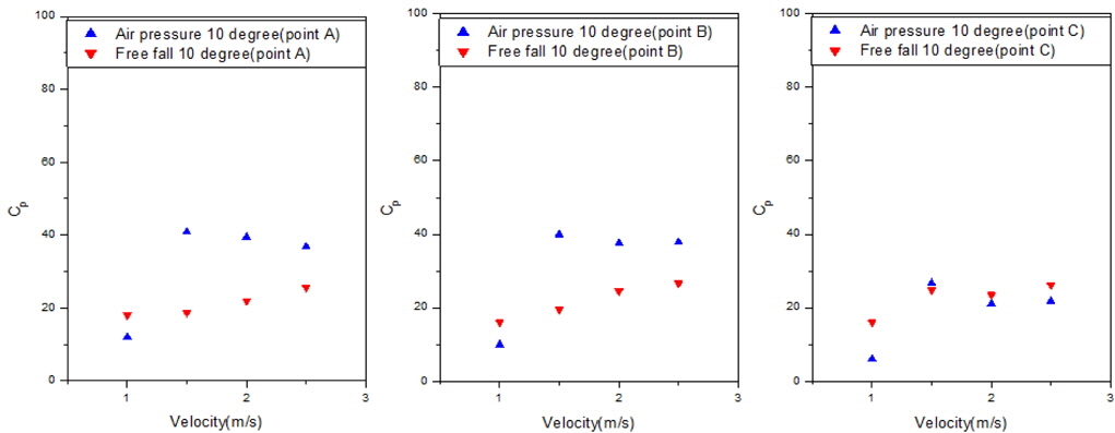
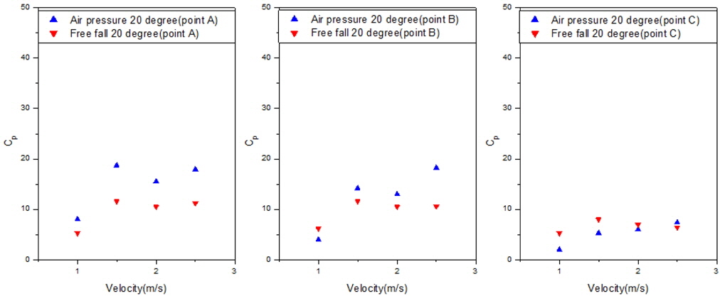
Fig. 6 shows the experimental set-up condition for the slamming impact test using the pneumatic cylinder. The guide was installed around the wave flume, and the cylinder was fixed on the guide. The wedge-shaped specimen was attached to the end of the cylinder. The cylinder was discharged by air pressure, and the specimen hit the water surface. The discharge velocity of the pneumatic cylinder was controlled by a regulator and we could manage water-entry velocities of 2.5 m/s, 2.0 m/s, 1.5 m/s, and 1.0 m/s, as determined by the high-speed camera. The pneumatic cylinder test was carried out using 10 degree and 20 degree deadrise angles with water-entry velocities of 2.5 m/s, 2.0 m/s, 1.5 m/s, and 1.0 m/s. Figs. 7 and 8 show the pressure results for points A, B, and C for each case.
5. Comparison Between Numerical and Experimental Results
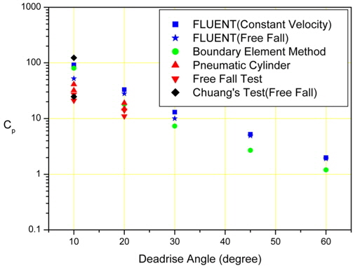
Fig. 9 shows a comparison of the experimental and numerical results. A comparison is shown of the 10 and 20 degree deadrise angles for the experimental results and 10, 20, 30, 45, and 60 degree deadrise angles for the numerical results.
All of the pointed values represent the mean values of the non-dimensionalized values.
In the case of the 10 deadrise angle, the computational result from FLUENT with a constant velocity is the highest value, and the result of the free fall test is the lowest value. In the case of the 20 deadrise angle, the computational result from FLUENT for a free fall is the highest value, and the result of the free fall test is the lowest value. The computational results from BEM are always located at the middle of the values, and the results of the pneumatic cylinder test are higher than the results of the free fall test. This means that the numerical results are generally higher than the experimental results.
The experimental and numerical results for the 10 deadrise angle are compared with the results of Chuang's drop test. The two points represent the maximum and minimum values of Chuang's results. Most of our results are located in the range of Chuang's test results.
A comparison of the conditions is shown in table 4 below.
This paper presented the results of two kinds of numerical computations and two kinds of experiments. When it comes to the numerical computation, one represents the potential code and another by viscous one in the numerical computations. The potential code was programmed based on BEM, which is the typical computational tool for a potential problem. The commercial code, FLUENT was utilized to simulate the viscosity and free fall motion. A free fall test is the traditional method used to determine the slamming impact, but we introduced the LM-Guide for an easy and exact test. This pneumatic cylinder test is a new and simple method proposed in the present research.
[Table 4] Ccomparison of conditions
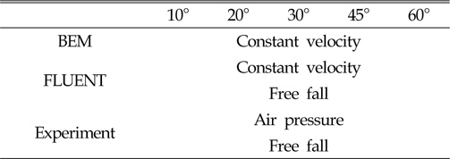
Ccomparison of conditions
The developed BEM code show good agreement with Fatlinsen's results. It seems that the developed BEM code complied with the slamming phenomenon. The required mesh generation and boundary condition imposition seemed suitable to describe the slamming phenomenon. When it came to the FLUENT code, the numerical values were higher than the BEM and experimental results. One promising feature derived from the FLUENT computation was that we could see the generation of a jet flow and its corresponding free surface evolution, which could not be achieved with BEM because it cannot simulate a separated flow.
The usual computations done in the field of slamming are based on the constant velocity assumption. This may be a very convenient assumption in the computation but does not seem to describe the actual slamming phenomenon. The present study considered the interaction between the body and the fluid using the UDF in the FLUENT calculation.
All of the experimental results were lower than the numerical results and these results were in good agreement with each other. All of the experimental and numerical results indicated that the deadrise angle is the most important factor in a slamming impact.