Amplified passive optical network (PON) architecture has been considered as a promising solution for the costeffective implementation of optical subscriber networks [1-5]. This is because the extended-reach of amplified PONs can enable us to reduce the number of network elements. Thus, various amplified PON architectures based on time-division multiplexed (TDM) and/or wavelengthdivision multiplexed (WDM) technology have been proposed and demonstrated by using different types of optical amplifier or reach extender [1-5]. For the cases of amplified WDM-PONs, the wavelength specific sources, such as distributed feedback (DFB) lasers and wavelength tunable lasers, have been usually used as WDM optical sources [4, 5]. However, it has been well known that broadband light source (BLS) based optical sources could be more costeffective than wavelength specific sources, and thus well suited for the implementation of WDM-PONs due to their colorless operation capability [6, 7]. In BLS seeded optical sources, an array of semiconductor devices, such as reflective semiconductor optical amplifiers (RSOAs) and Fabry-Perot laser diodes (FP-LDs), is used for the generation of WDM downstream or upstream signals with a single BLS. Here, the RSOA or FP-LD can be used for a modulation and an amplification of each downstream or upstream signal. However, due to the wide source bandwidth of the BLS based optical source, the chromatic dispersion of transmission fiber could limit the performance of BLS based extendedreach WDM-PON [8]. Another limiting factor in the extended-reach WDM-PON based on BLS seeded optical sources might be a round-trip transmission loss of BLS output for upstream signal generation, since both BLSs for downstream and upstream signals are generally located in central office (CO) [6, 9].
To resolve these problems, we have proposed and demonstrated a novel bidirectional reach extender module [10]. The proposed bidirectional reach extender located at remote node (RN) could not only amplify both downstream and upstream signals, but also provide a BLS output for upstream signal generation. In [10], using a dispersion compensating fiber (DCF) module located at CO, we have achieved an error-free transmission of both 1.25 Gb/s downstream and upstream signals over a 100 km single mode fiber (SMF) link. However, due to a high insertion loss of DCF module, the degradation of optical signal-tonoise ratio (OSNR) was observed especially for the downstream signals, which might be a main obstacle for the reach increase beyond 100 km. Moreover, using a single DCF module for both downstream and upstream signals might limit the flexibility of optical subscriber networks. Therefore, instead of using a DCF module, we have also evaluated the feasibility of chirped fiber Bragg grating (FBG) based channel-by-channel dispersion compensators in our proposed amplified WDM-PON architecture [11]. The chirped FBGs located CO and Optical Network Units (ONUs) were used for the dispersion compensation of upstream and downstream signals, respectively. However, placing a chirped FBG in each ONU would limit the colorless operation and increase the implementation cost of OUNs in the proposed amplified WDM-PON. Therefore, in this paper, we have modified and demonstrated an amplified WDM-PON architecture using the chirped FBGs based dispersion compensators which were located only at CO. From the measurements, we have confirmed that the OSNRs of downstream signals could be improved to be ~28 dB due to the low insertion loss of chirped FBG based dispersion compensator. In addition, we have evaluated the effect of various noise sources (such as OSNRs of downstream and upstream signals, gains of reach extender, output power of BLS) on the maximum reach of our amplified WDM-PON architecture. From the results, we believe that the proposed WDM-PON architecture can accommodate the different length of distribution fiber for each subscriber and the maximum reach of longer than 100 km.
II. PROPOSED AMPLIFIED WDM-PON ARCHITECTURE
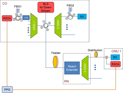
Figure 1 shows the proposed amplified WDM-PON architecture implemented with BLS seeded RSOA sources, chirped FBG based channel-by-channel dispersion compensators and a bidirectional reach extender module. Downstream WDM signals were generated with an array of RSOAs, an arrayed waveguide grating (AWG 1), a 3-dB coupler, two 4-ports circulators and a BLS. The output of BLS were spectrally sliced after passing through a 4-ports circulator and an AWG 1 and launched into each RSOA via a 3-dB coupler and a second circulator. Each RSOA was used to modulate and amplify each downstream signal. The output from each RSOA was launched into a chirped FBG (FBG1) for the pre-compensation of fiber chromatic dispersion, and then wavelength multiplexed with an AWG 1 again. The downstream WDM signals were launched into a feeder fiber after passing through a 4-ports circulator. The transmitted downstream WDM signals were amplified with a bidirectional reach extender module and demultiplexed with an AWG 2 at RN. Especially, an AWG 2 was assumed to have a cyclic characteristic, in order to transmit both downstream and upstream signals through a single distribution fiber to each ONU. Then each downstream signal was received at each ONU after passing through a distribution fiber and a WDM.
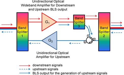
For upstream WDM signal generation, each OUN had an RSOA for a signal modulation and amplification, as shown in Fig. 1. Unlike a conventional BLS seeded optical sources based WDM-PON where a BLS for the upstream signal generation was located at CO [6, 9], a spectrallysliced BLS output was provided to each ONU from the bidirectional reach extender module located at RN [10]. Thus, in our proposed WDM-PON architecture, the BLS output for the upstream signal generation could be provided to each ONU without experiencing the transmission loss of feeder fiber, which, in turn, enabled us to increase the maximum reach of the proposed WDM-PON. Figure 2 shows a schematic diagram of the bidirectional reach extender module used in our proposed WDM-PON architecture [10]. The bidirectional reach extender module was implemented with three band splitters, two unidirectional amplifiers and a circulator. Two band splitters (1 and 2) were used to separate the paths of the downstream and upstream WDM signals. The downstream WDM signals could be amplified passing through a band splitter 1 and a wideband amplifier (having a gain of G1), a band splitter 3, and a band splitter 2. A wideband amplifier (G1) could not only amplify the downstream WDM signals, but also provide a BLS output for the upstream signals generation. Therefore, without a band splitter 3 and a circulator (port 1 and 2), the BLS output from the wideband amplifier could not be transmitted to each ONU, since the band splitters would filter out the BLS output for the upstream signals generation. In case of the upstream transmission, upstream WDM signals could be amplified after passing through a band splitter 2, a circulator (port 2 and 3), a unidirectional optical amplifier (having a gain of G2) and a band splitter 1 in our bidirectional reach extender module. Then, the amplified upstream WDM signals could be transmitted to CO via a feeder fiber link and demultiplexed with an AWG 3, as shown in Fig. 1. Finally, each upstream signal could be received after post-compensating the dispersioninduced distortion by use of a chirped FBG (FBG2) and a 3-ports circulator.
In order to demonstrate experimentally the feasibility of our amplified WDM-PON system, two C-band erbiumdoped fiber amplifiers (EDFAs) were used in the bidirectional reach extender module for the amplification of downstream and upstream WDM signals. Considering the output spectrum of conventional EDFA, we allocated the separated wavelength band for the downstream (ranging from 1542 nm to 1558 nm) and upstream (ranging from 1522 nm to 1538 nm) signal transmission. In our demonstration, the distribution fiber was temporarily placed in-between the bidirectional reach extender and an AWG 2 to evaluate the effect of bidirectional signal transmission over a single distribution fiber without using a cyclic AWG [10]. Then, center wavelengths of downstream and upstream signals were assigned to different output ports of AWG 2, which were 1549.3 nm and 1531.1 nm, respectively. Both downstream and upstream signals were modulated with a 1.25 Gb/s non-return-to-zero (NRZ) pseudorandom pattern of length 231-1. In addition, a 75 km and a 25 km SMF links were used as a feeder and a distribution fiber, respectively. In our BLS seeded RSOA sources, a 3-dB bandwidth of signal was determined by the passband of AWG which was measured to be ~0.4 nm in our experimental setup. Due to this wide 3-dB bandwidth of the BLS seeded RSOA source, the chromatic dispersion of transmission fiber could degrade the signal quality even for a 1.25 Gb/s transmission over a 100 km of SMF link. To mitigate the dispersion-induced distortion, two chirped FBGs were fabricated and used as the dispersion compensators for each downstream and upstream channel in the proposed amplified WDM-PON.
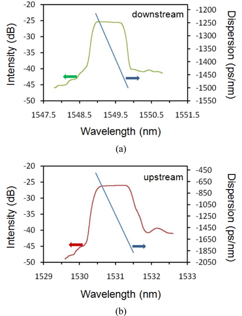
As shown in Fig. 3, we first measured the reflection spectra and the dispersion characteristics of two chirped FBGs used for the downstream and upstream signals. From the measured spectra, we confirmed that the center wavelengths of two chirped FBGs were well matched to ones of the downstream and upstream signals used in our experimental demonstration. Each chirped FBG had a 3-dB bandwidth of >0.8 nm, which was wide enough to pass the downstream or upstream signal without a significant narrowing of signal bandwidth. In addition, the insertion losses of two chirped FBGs were measured to be less than 3 dB including the insertion loss of a circulator. The dispersion values of two chirped FBGs were also measured to be -1320 ps/nm (@ 1549.3 nm) and -1150 ps/nm (@ 1531.1 nm), respectively. Thus, the accumulated dispersion of a 100-km SMF link (which would be ~1700 ps/nm) would be under-compensated with both chirped FBGs. Thus, the residual dispersions were estimated to be ~380 ps/nm for the downstream signal and ~650 ps/nm for the upstream signal, respectively. The dispersion slopes of two chirped FBGs were also estimated to be -285 ps/nm2 and -1380 ps/nm2 for downstream and upstream signals, respectively. From the results, we found that the dispersion slope characteristic of the chirped FBG for the upstream signal was very steep, compared to one of chirped FBG for the downstream signal. However, in order to evaluate the effect of dispersion slope on the system’s performance, we decided to use both chirped FBGs in our amplified WDM-PON instead of fabricating a new chirped FBG for the upstream signal.
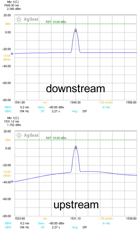
Then, the power levels of both signals were measured at various points in our amplified WDM-PON, as summarized in Table 1. The input powers into the bidirectional reach extender were measured to be -25.2 dBm for the downstream signal and -11.8 dBm for the upstream signal, respectively. From the measured power levels, the gains of our bidirectional reach extender module were estimated to be 27.5 dB in the downstream direction and 13 dB in the upstream direction, respectively. The output spectra of both signals after the bidirectional reach extender module were also measured with a 0.2 nm resolution of an optical spectrum analyzer (OSA), as shown in Fig. 4. From the measured spectra, the optical signal-to-noise ratios (OSNRs) of both signals were estimated to be 28 dB for the downstream signal and 32 dB for the upstream signal, respectively. In [10] where we used a dispersion compensating fiber (DCF) module in an amplified WDM-PON using BLS seeded optical sources, the OSNR of downstream signal was measured to be 15 dB due to a high insertion loss of DCF module. Thus, an additional power penalty of ~0.9 dB was observed owing to this low OSNR of the downstream signal [10]. We also confirmed that this additional penalty could be reduced by increasing an OSNR of signal to be more than 27 dB [10]. Therefore, in our new amplified WDM-PON architecture (@ OSNR of 28 dB in downstream signal), we believe that the low OSNR induced power penalty could be mitigated efficiently because of the low insertion losses of chirped FBG based dispersion compensators.
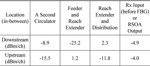
Measured powers of downstream and upstream signals at various points in our amplified WDM-PON
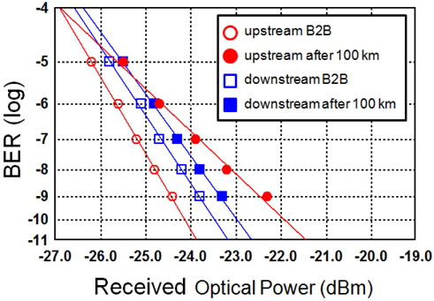
In order to evaluate the effect of dispersion-induced distortion on the performance of our proposed WDM-PON system, we measured the bit-error-rate (BER) curves of both downstream and upstream signals in a back-to-back configuration and after a transmission of 100 km SMF link, as shown in Fig. 5. From the results, we found that a penalty of ~0.5 dB in receiver sensitivity (@ BER = 10-9) was observed in the downstream signal transmission due to the residual dispersion (~380 ps/nm) [12]. In case of the upstream signal transmission, a penalty was increased to be ~2 dB due to the residual dispersion (~650 ps/nm) as well as the steep slope of dispersion. Even though these dispersion-induced penalties were induced by the under-compensation of dispersion value and the imperfection of dispersion slope characteristics of the chirped FBG based compensators, an error-free transmission over a 100 km SMF link was achieved without a BER floor in both directions.
From the measured results, we could also evaluate the impact of various noise sources on the maximum reach of the proposed amplified WDM-PON. In case of the downstream signal transmission, the input power into an optical receiver was measured to be -4.9 dBm, as shown in Table 1. Therefore, there existed about 19 dB power margin, since the sensitivity of our receiver was measured to be ~-24 dBm (@ BER = 10-9). This power margin could be increased by simply adjusting the gain of amplifier (G1) in the bidirectional reach extender module. Thus, we believe that the OSNR degradation due to the low input power into the bidirectional reach extender module would be the main limiting factor on the downstream signal transmission in our proposed amplified WDM-PON. In [10], we achieved an error-free downstream signal transmission with an OSNR of 15 dB and a power penalty of 2 dB. Thus, by considering the measured OSNR of 28 dB in the downstream direction, there was a 13-dB OSNR margin with a guideline of 2-dB power penalty. This ~13-dB OSNR margin might be simply equivalent to the feeder fiber increase of ~50 km (@ fiber transmission loss of 0.25 dB/km), since the OSNR of downstream signal would be mainly determined by the input power level of the reach extender. For the case of the upstream signal transmission, the input power into an optical receiver was measured to be ~-21 dBm from Table 1 and by including insertion losses of circulator, an AWG 3 and a chirped FBG. However, this input power could be also increased by adjusting the gain of amplifier (G2) in the bidirectional reach extender module. Thus, the output power level of BLS located at RN would be the main limiting factor on the upstream signal transmission in our proposed amplified WDM-PON [9]. From these considerations, we concluded that the main limiting factor on the maximum reach of our WDM-PON architecture would be the OSNR degradation of downstream signal due to the longer transmission length of feeder fiber than distribution fibers. Thus, unlike the conventional WDM-PONs using BLS seeded optical sources [6, 9]; the performance of downstream signals would limit the maximum reach in our proposed amplified WDM-PON architecture. From the results, we confirm that the proposed amplified WDM-PON with a 13 dB OSNR improvement in the downstream signal can easily accommodate a reach of longer than 100 km with high gain of amplifiers in the bidirectional reach extender module.
We have demonstrated an amplified WDM-PON using cost-effective BLS seeded RSOA optical sources in both downstream and upstream directions. An error-free transmission of 1.25 Gb/s signals over a 100 km SMF link was achieved even with the residual dispersion and the steep dispersion slope of chirped FBG based dispersion compensators. Moreover, due to the low insertion losses of the chirped FBG based dispersion compensators, we confirmed that the OSNRs of both downstream and upstream signals were measured to be larger than 28 dB, and then the maximum reach of the proposed amplified WDM-PON could be increased easily to be longer than a 100 km. Thus, we believe that the proposed amplified WDM-PON architecture would be well suited for the implementation of extendedreach PON systems.


![Schematic diagram of bidirectional reach extender module used in the proposed amplified WDM-PON architecture [10].](http://oak.go.kr/repository/journal/14661/E1OSAB_2014_v18n5_436_f002.jpg)