Recently, carbon nanofibers have attracted considerable attention in sensors, energy storage, and super-capacitors because of their physical dimensions, electrical conductivity, high mechanical strength, and high strength-to-weight ratio. Carbon nanofibers have also attracted increased attention as electrode material because they have the following advantages: 1) wide electrochemical stability window; 2) excellent biocompatibility; 3) low cost; and 4) chemical inertness.
Fabrications of the nanofiber electrode were introduced by using an electrospinning method.
The electrospinning technique enables cost-ffective production of continuous nanofibers for various materials compared to the conventional mechanical fiber spinning techniques [1,2]. With the reduction in fiber diameter, the fiber’s mechanical properties are known to be considerably improved and provide a larger surface-area-to-volume ratio and higher length-todiameter ratio [3,4]. There are many types of precursors, such as polycrylonite (PAN)/N, N-dimethlformamide (DMF) solution, pitches, and hydrocarbon gases used in the synthesis of carbon nanofibers by electrospinning. However, there is few researches on the electrospinning of epoxy-based negative photoresist SU-8 as the polymer precursor and subsequent pyrolysis of SU-8 [5-7 ].
SU-8 photoresist derived carbon nanofibers using carbon-micromechanical systems (C-MEMS) technology can be an answer for compact energy storage or conversion devices such as micro batteries and fuel cells. Moreover, SU-8 allows cost-effective microscopic patterning by conventional lithography without using reactive ion etching or patterned collector, and its fabrication process is compatible with the general semiconductor process. Despite the unique potential of electrospinning technique for low cost electromechanical control of SU-8 fiber and integrated manufacturing of two-and three-dimensional nanofiber assemblies, few studies have reported SU-8 derived electrospun carbon nanofibers electrodes for electrochemical energy storage system [8].
In this paper, we adopted negative PR SU-8 derived carbon nanofibers for further studies on developing the electrode of a Lithium ion battery. We investigated characteristics of SU-8 electrospun fibers with the variation of governing parameters to determine the average nanofiber diameter. Patterning was performed with a standard ultraviolet (UV) photolithography process. The resistivity went down as the terminal temperature increased, and pyrolysis yielded very similar material to glassy carbon.
An epoxy-based negative photoresist SU-8 2025 (Microchem. USA) was used for the fabrication of nanofibers. The apparatus for the electrospinning system consisted of a high voltage dc power supply (ESN-HV30, Nanonc, Inc., Korea), a syringe pump (KDS 100, KD Scientific, Inc., USA), and a 5 ml syringe with a 0.4 mm diameter tip. SU-8 has very low electrical conductivity and, therefore, very high voltages were applied during electrospinning. To investigate the variation of diameters of electrospun fibers, the applied voltage and distance between the syringe tip and target varied, ranging from 11 to 19 kV and from 7.5 to 25 cm, respectively. Also, the flow rate of the syringe pump varied from 1.25 to 20 ml/h. In photo-lithography process, electrospun fibers deposited on silicon were exposed for 180 seconds with a 365 nm UV exposure system (OS-1K, JSE, Inc., Korea).
To completely polymerize the fibers before carbonization, post exposure baking needs two minutes at 65℃ followed by six minutes at 95℃. Hard baking is then needed at 150℃ for 30 min. The hard baking step on photoresist-derived electrospun fibers for cross-linkage prevents the patterned electrospun fibers from being burned away during carbonization. The pyrolysis process was performed at 700, 750, 800, 850, or 900℃ under inert N2 atmosphere and the electrospun SU-8 nanofibers were converted to carbon nanofibers for each condition.
The weight loss during the pyrolysis of SU-8 electrospun fiber mat was measured using thermogravimetric analysis (TGA). For the TGA, a free-standing fiber network was collected on a rectangle type copper frame by electrospinning. The free-standing fiber network was removed from the rectangle type copper frame after drying for 1 h. It was exposed to the 365 nm UV exposure system for 5 min. A post exposure bake was performed at 65℃ for 2 min. and at 95℃ for 6 min. A subsequent hard bake was performed at 150℃ for 30 min. to complete the polymerization. TGA was performed by using the Shimadzu’s TGA-50 measurement machine in the temperature range of 30℃ to 900℃ at a heating rate of 10℃/min. N2 atmosphere was maintained with the flow rate of 100 ml/min.
The SU-8 fibers were pyrolyzed and shrunk into carbon nanofibers. Then their diameter and surface morphology were analyzed by FE-SEM (Sigma, Carl Zeiss, Inc., Germany) and XPS (Maker : PHI 5000 VersaProbe(Ulvac-PHI). To see the extent of graphitization, the resistivity of SU-8 derived carbon film was measured by four-point-probe (CMT Series, Chang Min Co., Ltd., Korea) under a variety of terminal temperatures of pyrolysis. The carbon nanofibers’ graphitization and physical properties were further analysed via Raman spectroscopy.
SU-8 fibers were electrospun on stainless steel 304 as a current collector and then used as the working electrode after pyrolysis. During the electrospinning process, the parameters were fixed at 15 kV applied voltage, 5.0 ml/h flow rate, 15 cm working distance, and 5 min processing time. In contrast with the process in SU-8 film, a soft bake was not performed to avoid the melt-down of SU-8 fibers. The electrospun SU-8 fibers which were deposited on stainless steel 304 were exposed for 10 min with 365 nm UV exposure systems (OS-1K, JSE, Inc., Korea). A post exposure bake was performed at 65℃ for 2 min and at 95℃ for 6 min. A subsequent hard bake was performed at 150℃ for 30 min in a convection oven to complete the polymerization. The pyrolysis process was performed at 900℃ under inert N2 atmosphere and the electrospun SU-8 nanofibers were converted to carbon nanofibers.
To investigate the electrochemical characteristics of SU-8 derived carbon nanofibers anode, SU-8 fibers were electrospun on stainless steel 304 as a current collector, and after pyrolysis, were then used as the working electrode. Lithium cobalt oxide (LiCoO2) was applied to the counter electrode and polypropylene was used as the separator. The nonaqueous electrolyte was 1M Lithium Hexafluorophosphate (LiPF6) in a mixed solution of 1:1:1 volume of ethylene carbonate (EC), diethyl carbonate (DEC) and dimethyl carbonate (DMC) and the cell type was self-producing. All the manufacturing of lithium ion cells were processed at room temperature inside an argon filled glove box. The electrochemical properties of carbon fibers were studied via potentiostat/ galvanostat (EG&G Princeton Applied Research, Model 273A), impendence measurement unit (IM6ex,
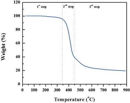
Figure 1 shows the TGA profile of SU-8 electrospun fiber mat. During the first step, there is no remarkable decrease in weight. The notable weight loss of SU-8 occurs in the second step between 350℃~450℃ and continues all the way up to 900℃ in third step with a heating rate of 10℃ /min at N2 atmosphere. Distinct weight loss begins around 350℃, and the inclination decreases after 450℃.
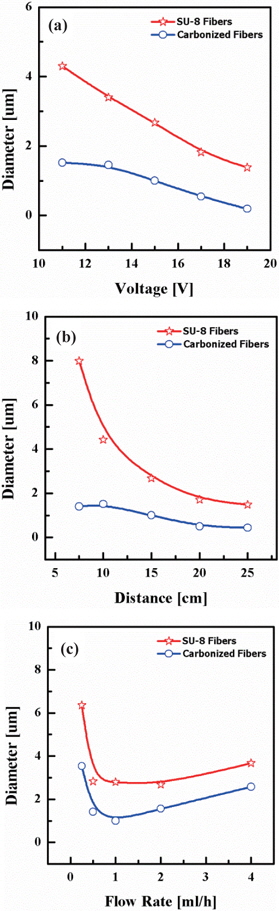
SU-8 photoresist was used for the electrospun fibers with the various conditions of parameters. One of the most significant quantities in the relation to electrospinning is the average diameter of fibers. three governing parameters were determined to control the diameter of electrospun fibers: the applied voltage, electrospinning distance between syringe tip and collector, and flow rate of the syringe pump. Figures 2(a), (b), and (c) show the effect on the diameters of fibers as functions of the working distance, the applied voltage induced between syringe tip and collector, and the flow rate of the syringe pump.
In Fig. 2(a) the diameters of electrospun fibers tended to decrease when the applied voltage or the distance increased. The applied voltage varied in the range of 11 kV~19 kV. The flow rate in the syringe pump and working distance were fixed at 5 ml/ h and 15 cm, respectively. As the applied voltage increased the average diameter of electrospun fibers decreased. The terminal diameter of the polymer jet is determined by the interaction among the viscosity, electrical field induced between the two electrodes, and surface tension. Electrical charges applied on multiple jets have characteristics of repulsing other jets, and then the electrostatic charge repulsion from the electrospinning path of jets contributes to the reduction of fiber diameter [9]. More multiple jets were ejected from the Taylor cone at the tip as higher voltage was applied. The electrical force and the number of multiple jets affected the factors: the volume of polymer jet ejected from the syringe tip and the elongation level of the jet. The balance among these factors can influence the average diameter of terminal fibers on the grounded collector [10]. A reduction in diameter during heat treatment confirms the weight loss in TGA plot of Fig. 1. After pyrolysis, the average fiber diameter reduced to 35%.
As the upper graph of Fig. 2(b) shows, the average diameter of electrospun fibers decreases with increasing working distance. The applied voltage and flow rate of polymer solution did not vary, but were fixed at 15 kV and 5.0 ml/h, respectively.
While jets travelled the distance between tip and collector, the whipping jets became dramatically thinner. The longer distance they travelled, the more solvent that evaporated, and as well, the path of the jets changed [9].
Figure 2(c) shows that in determining the average diameter of fibers, the volumetric feed rate was less effective than the distance and the applied voltage. The applied voltage and working distance were fixed at 15 kV and 15 cm, respectively.
The average diameters of fibers show that the inclination was decreasing until 5.0 ml/h, and increasing after 5.0 ml/h of volumetric flow rate. When the flow rate was low, the insufficient amount flow of polymer through the syringe tip didn’t make the Taylor cone properly and the jet intermittently cut off while coming out from the syringe tip, which contributed to the agglomeration of the fibers and the increase of fiber diameters. On the other hand, when the flow rate was high, the uncharged solution dripped out of the syringe tip before arriving at the target collector, and some drips, which were charged, arrived at the target collector, contributing to increasing of the average diameter of fibers.
By the optimization of flow rate, it can be determined that a flow rate of 5ml/h is needed to yield uniform fiber diameters. Figs. 2(b) and (c) also show the shrinkage of carbon nanofibers during the carbonization process with the terminal temperature of 900℃. The average diameters of the carbon nanofibers decreased to 26.5% and 55.1%, respectively from the original SU-8 fiber diameter.
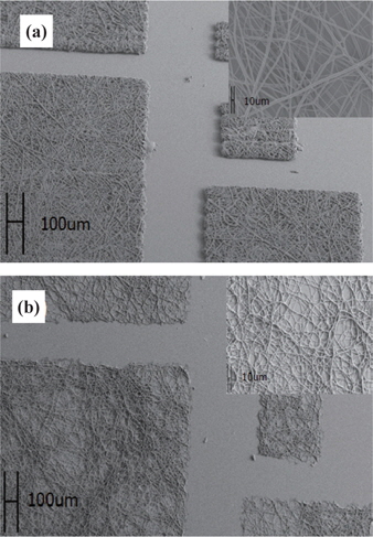
As shown in Fig. 3(a), SEM images of patterns developed by exposing UV light would be cross-linked and remanent. SU-8 electrospun fibers were patterned and carbonized with pyrolysis as shown in Fig. 3(b). Comparing the upper right image in Fig. 3(a), the diameters of the upper image in Fig. 3(b) decreased, as described in Fig. 2, and the morphology of SU-8 electrospun fibers was conserved through the pyrolysis process.
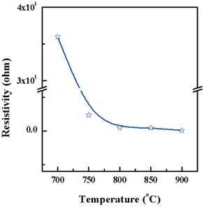
A carbonized thin film was prepared for resistivity measurement after pyrolysis using a four-point-probe. Figure 4 shows the resistivity decreases dramatically when increasing the tem- perature of pyrolysis. This result means that the graphitization progressed with an increasing of temperature [11]. There is a contrast in the resistivity of 35.9775 Ω·cm at 700℃ and the resistivity of carbonized film of 0.0396 Ω·cm when the terminal temperature of pyrolysis is 900℃.
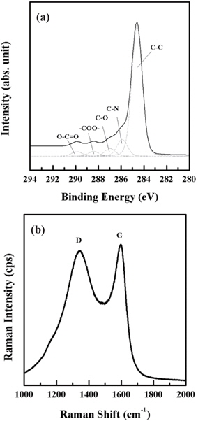
Figure 5(a) shows the C 1s peaks of XPS with the deconvoluted spectra. The C 1s peak can be deconvoluted into three peaks: C-C, C-N, and C-O bonds. C-N bond results from carbonization process under the N2 atmosphere. C-O bond is due to the result of autoxidation after the pyrolysis. Carbonization of the photolithographically defined SU-8 yields a complete glassy carbon as expected. Carboneous material can be also identified by the Raman spectra of SU-derived carbon fibers as Fig. 5(b) shows. We observed D and G peaks centered at around 1,342 cm-1 and 1,597 cm-1. The high peak intensity ratio (ID/IG) near to 1.0 shows the high amorphous nature of carbon and low crystallinity [12].
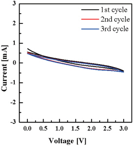
Figure 6 shows a cyclic voltammogram of SU-8 derived carbon nanofiber measured over the range from 3.0 V to 0 V with a scan rate of 5 mV/s. The voltage was swept between two voltage values, 0 V and 3.0 V. When the voltage increased from 0 V to 3.0 V at a scan rate of 5 mV/s, the scan inverted and the voltage swept back to 0 V. Each curve shows lithium intercalation into the carbon nanofibers electrode.
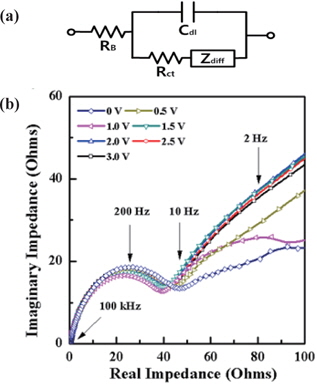
Impedance spectroscopy data can be explained with the equivalent circuit shown in Fig. 7, where RB is the ohmic resistance, Rct is the charge transfer resistance or the polarization resistance, Cdl is double layer capacitance in the interface between the electrolyte region and the electrode region, and Zdiff is the diffusion impedance of Lithium ions. At high-frequency, the value on the real impedance axis confronting the impedance plot is the ohmic resistance, RB. In Fig. 7(b), the value of RB was around 0.44 Ω at 0 V. The semicircle between 100 kHz and 10 Hz is formed by the charge transfer resistance (Rct) in parallel with the double layer capacitance (Cdl). The contact point of semi-circle virtually extended to the real impedance axis corresponds to the sum of the value of the charge transfer resistance and the value of the ohmic resistance (RB + Rct). The charge transfer resistances for each voltage have relatively stable values and were observed under the resistance of 60 Ω. Diffusion of lithium ions toward the surface of electrode occurring at the low frequency region below 10 Hz is due to the diffusion impedance (Zdiff), which has two elements of diffusion capacitance (-1/ωZdiff) for the direction of the vertical imaginary impedance axis and diffusion resistance for the direction of the real impedance axis. The impedance plot shows the Warburg impedance, which is about 45° degree from the real impedance axis.
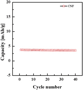
Figure 8 shows the cycling performance for carbon nanofibers electrode using a C/5 rate. The capacity at the first cycle was 3.79 mAh/g and the capacity decreased to 3.75 mAh/g at the second cycle. As the cycle number increased, the discharge capacity maintained 94% of its initial value and the capacity at the 40th cycle was 3.58 mAh/g. The variation of the discharge capacity shows the lifetime reliability of the manufactured energy storage device with SU-8 derived carbon nanofiber electrode.
In conclusion, we investigated the morphological, electrical, and electrochemical characteristics of pyrolyzed SU-8 derived carbon nanofibers for a full lithium ion cell electrode. We also suggest a simple and cost-effective process to produce the micropatterned carbon nanofiber. Various parameters including the applied voltage, the distance between syringe tip and target collector and the flow rate of the polymer can affect the diameter of SU-8 electrospun nanofibers. As inferred in the weight loss tendency of TGA data, we verified that shrinkage occurred during pyrolysis, and then fiber diameter decreased with retaining its morphology. To achieve the patterned electrospun fibers, the conventional lithography process was performed with UV exposure. The resistivity dramatically decreased, resulting in the characteristics of electrodes as pyrolysis temperature increased. All SU-8 polymer components changed into an amorphous carbon as shown in the XPS analysis and Raman spectra.
Given the advantages of carbon nanofibers having externally high surface areas and electrical conductivity, we applied SU-8 derived carbon nanofiber to the anode of a full lithium ion cell. SU-8 fibers were electrospun on the stainless steel 304 as a current collector, and after pyrolysis, were used as the working electrode. The electrochemical characteristics of the electrode were investigated by cyclic voltammogram and electrochemical impedance spectroscopy plots. The cycling performance for carbon nanofibers electrode confirmed the characteristics of lifetime reliability of the SU-8 derived carbon nanofiber electrode for the full lithium ion cell.