검색 전체 메뉴
PDF
맨 위로
OA 학술지
Neural Network Compensation for Impedance Force Controlled Robot Manipulators
  • 비영리 CC BY-NC
  • 비영리 CC BY-NC
ABSTRACT
Neural Network Compensation for Impedance Force Controlled Robot Manipulators
KEYWORD
Neural network , Impedance control , Robot manipulator
  • 1. Introduction

    Robot tasks have become increasingly sophisticated and complicated as our desire for robots has grown. Robots are gradually being used in our daily lives in more varied ways. Through their ability to manipulate objects, service robots are now required to interact more frequently with humans, beyond simple house cleaning chores. The corresponding technologies are necessary for robots to perform more challenging and sophisticated tasks including not only position control but also force control for two-arm manipulation.

    Indeed, in the near future, service robots should be able to handle objects to satisfy the specifications of their given tasks and to interact and cooperate with humans in a natural manner [1]. Robot interaction with humans and the environment requires active force control techniques.

    In robot research communities, force control is a sophisticated control methodology for robots interacting with their environment, including humans. To achieve successful force tracking performances, several problems need to be solved a priori. First, a direct force tracking capability for following the desired force command is required for the formulation of a control law. Second, accurate position tracking control should be achieved by compensating for uncertainties in robot dynamics. Third, uncertainties in estimating the environment, such as stiffness and location, should be properly addressed.

    Various control algorithms have been proposed to alleviate the aforementioned problems of force control tasks. From the pioneering works of impedance control and hybrid force control algorithms, to intelligent force control algorithms, many researches have been presented on this subject [2-5], and force control algorithms have been modified for an improved performance [6-10].

    The trend of merging the concept of intelligence into a system has yielded methods of intelligent force control. Neural network, which is known to be an intelligent tool, is utilized along with robot controllers to improve the tracking performance [11-22]. Neural networks are well known for their nonlinear mapping, adaptation, and learning capabilities, and many successful results have been reported in the literature. Fuzzy logic is also a well-known intelligent tool that interprets human expressions for a machine system. Although fuzzy logic controllers are considerably practical and can be easily implemented through hardware, fuzzy logic suffers from the setting of optimal fuzzy rules. Determining the optimal fuzzy rules is a time-consuming process [23].

    In a force control framework, neural network algorithms have been used for industrial manipulators to address both unknown objects and unknown robot dynamics [11-17]. A combined control structure for the both aHcontrol method and a neural network has been proposed [18]. In addition, to accelerate the advantages of fuzzy logic and neural networks, a combined structure called a neuro-fuzzy control scheme was proposed [19, 20, 24].

    In our previous research [11], a neural network was used for impedance control formulation to nullify any uncertainties. Experimental studies on regulating the contact forces for an x-y table robot have shown that a neural network performs considerably well for force tracking tasks in an on-line manner. Neural networks compensate for uncertainties at the control input level. This has led to modifications of the internal force control structure. In reality, however, many robots were designed for position control using sealed control structures that do not allow modifications of the control algorithms.

    In this paper, a different structure for the use of a neural network in a force-controlled robot manipulator [11, 13] is proposed. Here, a neural network is used to compensate for all uncertainties at the input trajectory level. This scheme is known as reference compensation technique used for the position control of robot manipulators [25, 26]. This structure provides a remarkable advantage from a structural point of view in that it does not require a modification of the pre-installed controllers in many applications used. Extensive simulations were conducted to show the feasibility of the proposed control method.

    2. Review of Impedance Control

    A dynamic equation of an n degree-of-freedom robot manipulator in the joint space coordinates can be given by

    image

    where vectors q, and are the n × 1 joint angle, n × 1 joint angular velocity, and n × 1 joint angular acceleration, respectively; D(q)is the n × n symmetric positive definite inertia matrix; C(q, ) is the n × 1 vector of the Coriolis and centrifugal torques; G(q) is the n × 1 gravitational torque; 𝜏is the n × 1 vector of the actuator joint torque; and 𝜏e is the n × 1 vector of the external disturbance joint torque.

    Denoting h = C(q, )+G(q) can simplify Eq. (1) as

    image

    The Jacobian relationship between the joint velocity and Cartesian velocity allows the development of a robot dynamic equation model in the Cartesian space. The Jacobian relationship for the acceleration is

    image

    Substituting (3) in (2) yields the following Cartesian dynamic equation:

    image

    where D* = JT–1 DJ–1, h* = JT–1 hD* J–1 , Fe is the external force, and F is the control input force.

    The impedance force control method regulates the contact force by correctly selecting the impedance parameters [10]. The force tracking impedance function can be given by

    image

    where E = XeX, Xe is the environment position, and M, B, K are the impedance parameters. Setting K = 0 in (5) and assuming Fe = −KeE yield a stable impedance function.

    image

    In this formulation, without knowing the exact environment stiffness Ke, the force tracking Fe = Fd is guaranteed under a steady state. If the environment position Xe is not accurately available such that X'e = Xe + δXe, impedance function (6) with uncertainty can be represented as

    image

    where E' = E+δXe, and δXe is uncertainty in the environment position.

    However, to achieve force tracking Fe = Fd by realizing the ideal impedance function, uncertainties in robot dynamics have to be concurrently compensated. Herein, we propose the use of a neural network to handle the uncertainties in both robot dynamics and the environment.

    3. Neural Network Force Control

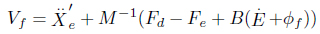
    The role of a neural network is to generate signals to compensate for uncertainties to minimize the tracking errors of position and force control. The force control law in the Cartesian space can be given by [9, 10]

    image

    Further, the control input is given as

    image

    Based on the impedance law in (5) and (6), can be modified by adding compensating signals from a neural network. The position control can be written as

    image

    where Mp, Bp, Kp are the position control gains, and ϕp is the output signal of the neural network used to compensate for uncertainties in the position controlled direction.

    The force control can be written as

    image
    image

    where ε = XdX, Xd is the desired trajectory, ϕf is the output of the neural network used for the compensation of the force controlled direction, and , where Vp indicates the position controlled direction, and Vf is the force controlled direction.

    Substituting the control law (8) in the Cartesian robot dynamic Eq. (4) yields

    image

    where and which are considered to be modeling errors. Arranging (12) provides the following closed loop error equation:

    image

    The force controllable direction is considered separately by substituting Vf of the contact in (11) in (13). We then have the following equation:

    image

    where the uncertainty terms are Thus, Eq. (14) can be simplified as a closed loop force error equation:

    image

    Therefore, the neural network compensating signal ϕf can compensate for those dynamic uncertainties, as

    image

    After driving a neural network to converge to zero, the neural network output becomes equal to the dynamic uncertainty.

    image

    The desired impedance function can then be realized as

    image

    where Fe = −KeE.

    In the same manner, we can obtain the following equation for the position controlled direction:

    image

    where ϕp is a neural network output for the position controlled direction. After convergence, the neural network output for the position controlled direction becomes

    image

    The desired position control can then be realized as

    image

    where Mp = I for a typical case.

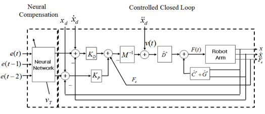
    The proposed neural network force control structure is shown in Figure 1. There are two control parts: a compensation control part and an impedance force control part. The robot manipulator is controlled using an impedance force control method. The compensation part is a totally separable structure from the impedance force control part such that it can be easily separated. The idea here is to modify the input trajectory signals to have effects of modifying gains in the internal controller. Therefore, next is how to drive neural network to generate compensation signals to make tracking errors go to zero.

    4. Neural Network Learning Algorithm

    Next is to design the training signal for driving the neural network to satisfy the goal. Our goal is to achieve Fe = Fd in the force controlled direction and X = Xd in the position controlled direction. A neural network is trained and learned in an on-line adaptive manner by minimizing the objective function composed of training signals.

    The learning algorithm is similar to those presented in [11, 13]. Therefore, we can determine the training signal from Eq. (7) as

    image

    Eq. (16) then becomes

    image

    where If the environment position profile is not flat, good force tracking results cannot be achieved owing to the , terms. To overcome this problem, we use a neural network to cancel out these terms in (23).

    Hence, the training signal for a neural network should be properly designed such that the force tracking error is minimized. Two separate training signals, 𝜐position, 𝜐force, were designed for the position control and force control, respectively. The training signals for 𝜐force are obtained from Eq. (5) for two cases: one in a free space, and the other in a contact space.

    image
    image

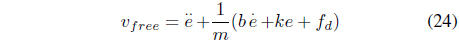
    The objective function to be minimized can be defined as

    image

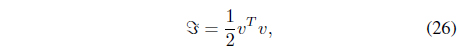
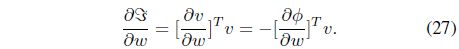
    where Employing the definition of v in Eqs. (24) and (25) yields the gradient of as 𝔍

    image

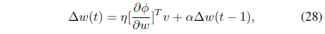
    The neural network output is The back-propagation update rule for the weights with a momentum term is

    image

    where 𝜂 is the update rate and 𝛼 is the momentum coefficient.

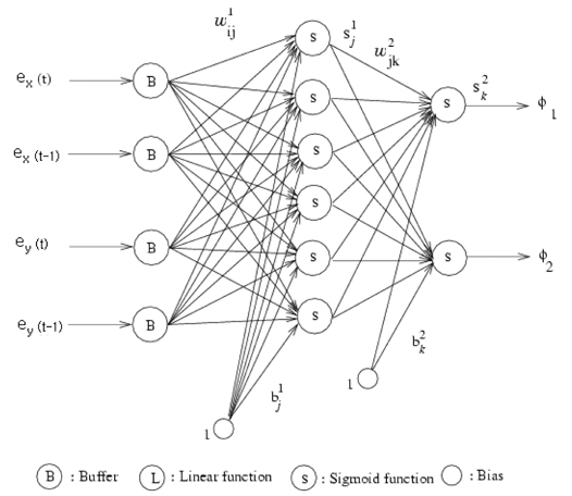
    A two-layered feed-forward neural network is used as a compensator, as shown in Figure 2. The output of the hidden units is filtered using a nonlinear function,

    image

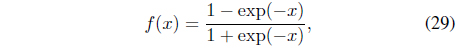
    while the output units are linear. We chose six hidden neurons for our experiments. The back propagation algorithm parameter 𝜂 was optimized, and 𝛼 = 0.9 was used. In addition, weights with small values were randomly selected.

    5. Simulation Results

       5.1 Simulation Setup

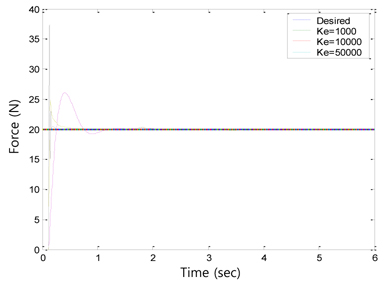
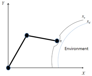
    To validate the proposed force control algorithm, simulation studies on a two-link robot manipulator were conducted. The link length is 0.4 m and the weight is 5 kg for two links. Robot dynamic uncertainties include cases in which the robot dynamics model is assumed to be unknown and each joint has friction terms. The environment was assumed to have an unknown stiffness of 10,000 N/m, and the desired force was set to 20 N. The force normal to the environment along the x axis was regulated. The sampling time was 0.005 sec. The robot was required to follow the environment along the y axis while regulating the desired force along the x axis, as shown in Figure 3.

       5.2 No Uncertainties in Robot Dynamics

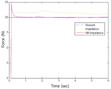
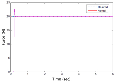
    First, the robot was required to track through an environment with a stiffness of 10,000 N/m. The desired force was 20 N. The force tracking results are shown in Figure 4. The position controller gains were kp = 100 and kd = 20, and the force controller gains were m = 1 and b = 100. From its initial position, the robot moved slowly and made contact with the environment at about 0.13 sec.

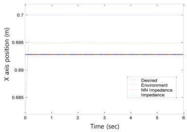
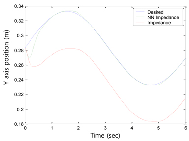
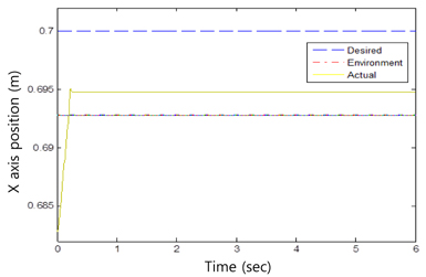
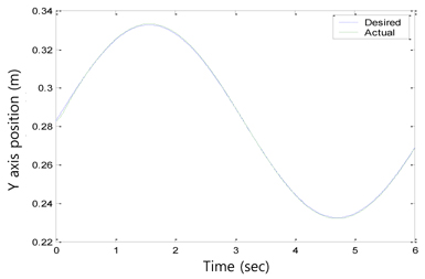
    Without knowing the environment stiffness or the position information, the impedance force control algorithm was sufficiently robust to perform force tracking control well. Tracking performances of x axis position and y axis sinusoidal trajectory are shown in Figures 5 and 6, respectively.

       5.3 Uncertainties in Robot Dynamics

    However, when uncertainties in robot dynamics such as joint friction and model mismatches are present, the force tracking performance is significantly degraded, as shown in Figure 7. The position tracking results for the y axis show a notable tracking error, as presented in Figure 8. This error should be alleviated to achieve a better force tracking performance.

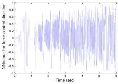
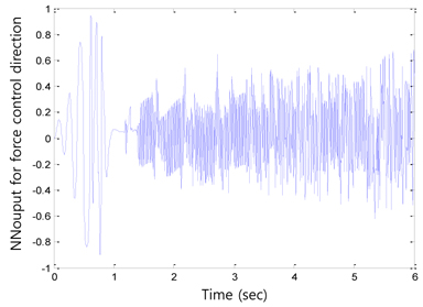
    After compensating for these uncertainties in robot dynamics, the force tracking performance was improved, as shown in Figure 7. The force overshoot was reduced to within 0:5 sec. The corresponding position tracking results in Figure 8 indicate that the environment position is estimated inside the environment. The position tracking along the y axis was also improved by the neural network controller, as shown in Figure 9. The initial tracking errors were also quickly minimized as the neural network learned. Figures 10 and 11 show the neural network compensation signals for the force and position controls, respectively.

       5.4 Different Environment Stiffness

    The next simulation was conducted to determine the effect of different environment stiffness. The desired force was set to 20 N. As expected, a larger force overshoot could be observed for a stiffer environment. For a stiffness of ke = 50,000 N/m, we obtained the largest force overshoot, as shown in Figure 12. However, it reduced quickly. For a stiffness of ke = 1, 000 N/m, which is considered to be a soft environment, the force response time was slower and a smaller force overshoot was obtained. The force tracking performance in Figure 12 shows that the controller is sufficiently robust to handle all cases of environment stiffness. The force overshoot caused the robot to exert more force on the environment than desired, which may have caused an undesirable contact with the environment.

       5.5 Different Force Tracking Tasks

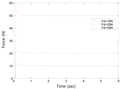
    In the next simulation, the robot was tasked to regulate different desired forces for the same environment stiffness of ke= 10,000 N/m. Different forces should be regulated under the same conditions. Figure 13 shows the tracking performance for each desired force tracking task. The proposed neural controller could handle different forces with the same controller gains within the same environment.

    6. Conclusion

    When the robot used force control, its performance was greatly affected by the robustness of the position controller. Robot dynamics uncertainties are one of the important problems that need to be solved in advance. Because a neural network is a nonlinear controller, uncertainties can be compensated in terms of not only the position controller but also the force controller. The performance of the proposed controller was confirmed through extensive simulations. One advantage of the proposed control scheme is that there are no modifications required for a pre-designed controller. Uncertainties can be compensated at the input trajectory level, which may lead to many advantages in real applications such as teleoperation control, haptic devices, and other nonlinear control systems. Future research will seek advantages by applying the proposed algorithms to applications.

참고문헌
  • 1. Kim D. M., Choi H. J., Kim J. S., Lee W. K., Song D. H., Jung S. 2007 “Tracking control of a moving object for robokers with stereo visual feedback,” [in IEEE International Conference on Integration Technology] P.52-57 google cross ref
  • 2. Hogan N. 1985 “Impedance control: an approach to manipulation. Part ITheory,” [Journal of Dynamic Systems, Measurement, and Control] Vol.107 P.1-7 google cross ref
  • 3. Hogan N. 1985 “Impedance control: an approach to manipulation. Part IIImplementation,” [Journal of Dynamic Systems, Measurement, and Control] Vol.107 P.8-16 google cross ref
  • 4. Hogan N. 1985 “Impedance control: an approach to manipulation. Part IIIApplications,” [Journal of Dynamic Systems, Measurement, and Control] Vol.107 P.17-24 google cross ref
  • 5. Raibert M. H., Craig J. J. 1981 “Hybrid position/force control of manipulators,” [Journal of Dynamic Systems, Measurement, and Control] Vol.103 P.126-133 google cross ref
  • 6. Anderson R., Spong M. W. March 31-April 3, 1987 “Hybrid impedance control of robotic manipulators,” [in Proceedings of the IEEE International Conference on Robotics and Automation] P.1073-1080 google cross ref
  • 7. Liu G. J., Goldenberg A. A. 1991 “Robust hybrid impedance control of robot manipulators,” [in Proceedings of the IEEE International Conference on Robotics and Automation] P.287-292 google cross ref
  • 8. Seraji H. May 8-13, 1994 “Adaptive admittance control: an approach to explicit force control in compliant motion,” [in Proceedingsof the IEEE International Conference on Robotics and Automation] P.2705-2712 google cross ref
  • 9. Jung S., Hsia T. C. May 10-15, 1999 “Adaptive force tracking impedance control of robot for cutting nonhomogeneous workpiece,” [in Proceedings of the IEEE International Conference on Robotics and Automation] P.1800-1805 google cross ref
  • 10. Jung S., Hsia T. C., Bonitz R. G. 2004 “Force tracking impedance control of robot manipulators under unknown environment,” [IEEE Transactions on Control Systems Technology] Vol.12 P.474-483 google cross ref
  • 11. Jung S., Yim S. B., Hsia T. C. May 21-26, 2001 “Experimental studies of neural network impedance force control for robot manipulators,” [in Proceedings of the IEEE International Conference on Robotics and Automation] P.3453-3458 google cross ref
  • 12. Dapper M., Maass R., Zahn V., Eckmiller R. May 16-20, 1998 “Neural force control (NFC) applied to industrial manipulators in interaction with moving rigid objects,” [in Proceedings of the IEEE International Conference on Robotics and Automation] P.2048-2053 google cross ref
  • 13. Jung S., Hsia T. C. 2000 “Robust neural force control scheme under uncertainties in robot dynamics and unknown environment,” [IEEE Transactions on Industrial Electronics] Vol.47 P.403-412 google cross ref
  • 14. Hu S., Ang V. M. H., Krishnan H. October 22-28, 2000 “NN controller of the constrained robot under unknown constraint,” [in 26th Annual Conference of the IEEE Industrial Electronics Society] P.2123-2128 google cross ref
  • 15. Mallapragada V., Erol D., Sarkar N. October 9-15, 2006 “A new method of force control for unknown environments,” [in IEEE/RSJ International Conference on Intelligent Robots and Systems] P.4509-4514 google cross ref
  • 16. Zhao Y., Cheah C. C. December 1-3, 2004 “Position and force control of robot manipulators using neural networks,” [IEEE Conference on Robotics, Automation and Mechatronics] P.300-305 google cross ref
  • 17. Passold F., Stemmer M. R. June 17-20, 2004 “Force control of a Scara robot using neural networks,” [in Proceedings of the Fourth International Workshop on Robot Motion and Control] P.247-252 google
  • 18. Hwang M. C., Hu X. 2000 “A robust position/force learning controller of manipulators via nonlinear Hinfinity control and neural networks,” [IEEE Transactions on Systems, Man, and Cybernetics, Part B: Cybernetics] Vol.30 P.310-321 google cross ref
  • 19. Kiguchi K., Fukuda T. 1997 “Intelligent position/force controller for industrial robot manipulators-application of fuzzy neural networks,” [IEEE Transactions on Industrial Electronics] Vol.44 P.753-761 google cross ref
  • 20. Kiguchi K., Watanabe K., Izumi K., Fukuda T. CA, April 24-28, 2000 “Application of multiple fuzzy-neuro force controllers in an unknown environment using genetic algorithms,” [in Proceedings of the IEEE International Conference on Robotics and Automation] P.2106-2111 google cross ref
  • 21. Song D. H., Lee G. H., Jung S. 2008 “Neural network compensation technique for standard PD-like fuzzy controlled nonlinear systems,” [International Journal of Fuzzy Logic and Intelligent Systems] Vol.8 P.68-74 google cross ref
  • 22. Cho H. T., Kim S. S., Jung S. 2008 “Experimental studies of real-time decentralized neural network control for an x-y table robot,” [International Journal of Fuzzy Logic and Intelligent Systems] Vol.8 P.185-191 google cross ref
  • 23. Kim H. W., Jung S. 2012 “Fuzzy logic application to a two-wheel mobile robot for balancing control performance,” [International Journal of Fuzzy Logic and Intelligent Systems] Vol.12 P.154-161 google cross ref
  • 24. Lee G. H., Jung S. 2009 “Neuro-fuzzy control of inverted pendulum system for intelligent control education,” [International Journal of Fuzzy Logic and Intelligent Systems] Vol.9 P.309-314 google cross ref
  • 25. Jung S., Hsia T. C. 2000 “Neural network inverse control techniques for PD controlled robot manipulator,” [Robotica] Vol.18 P.305-314 google cross ref
  • 26. Jung S., Cho H. T. 2004 “Decoupled neural network reference compensation technique for a PD controlled two degrees-of-freedom inverted pendulum,” [International Journal of Control, Automation, and Systems] Vol.2 P.92-99 google
OAK XML 통계
이미지 / 테이블
  • [ ] 
  • [ ] 
  • [ ] 
  • [ ] 
  • [ ] 
  • [ ] 
  • [ ] 
  • [ ] 
  • [ ] 
  • [ ] 
  • [ ] 
  • [ ] 
  • [ ] 
  • [ ] 
  • [ ] 
  • [ ] 
  • [ ] 
  • [ ] 
  • [ ] 
  • [ ] 
  • [ ] 
  • [ ] 
  • [ Figure 1. ]  Neural network force control structure.
    Neural network force control structure.
  • [ ] 
  • [ ] 
  • [ ] 
  • [ ] 
  • [ ] 
  • [ ] 
  • [ ] 
  • [ ] 
  • [ Figure 2. ]  Neural network structure.
    Neural network structure.
  • [ Figure 3. ]  Force tracking environment.
    Force tracking environment.
  • [ Figure 4. ]  Force tracking performance.
    Force tracking performance.
  • [ Figure 5. ]  X axis position tracking result.
    X axis position tracking result.
  • [ Figure 6. ]  Y axis position tracking result.
    Y axis position tracking result.
  • [ Figure 7. ]  Force tracking performance under robot dynamics uncertainty.
    Force tracking performance under robot dynamics uncertainty.
  • [ Figure 8. ]  X axis position tracking results under robot dynamics uncertainty.
    X axis position tracking results under robot dynamics uncertainty.
  • [ Figure 9. ]  Y axis position tracking results under robot dynamics uncertainty.
    Y axis position tracking results under robot dynamics uncertainty.
  • [ Figure 10. ]  Neural network compensation signal for force control direction.
    Neural network compensation signal for force control direction.
  • [ Figure 11. ]  Neural network compensation signal for position control direction.
    Neural network compensation signal for position control direction.
  • [ Figure 12. ]  Force tracking results for different environments.
    Force tracking results for different environments.
  • [ Figure 13. ]  Different force tracking when ke= 10,000 N/m.
    Different force tracking when ke= 10,000 N/m.
(우)06579 서울시 서초구 반포대로 201(반포동)
Tel. 02-537-6389 | Fax. 02-590-0571 | 문의 : oak2014@korea.kr
Copyright(c) National Library of Korea. All rights reserved.