Terahertz (THz) radiation, which is defined as the electromagnetic wave with frequency ranging from 0.1 THz up to 10THz, has attracted widespread attention in recent years because of its unique possibilities in many fields [1-4]. However, an efficient THz waveguide, which is of great importance for practical THz application, is still a major challenge that researchers are currently facing while trying to satisfy the strong demand for compact, low-cost and robust THz systems. In this paper, we propose a new high birefringent polymer THz fiber with a suspended elliptical core which will have potential in high-bit-rate communication system, polarization-maintaining fiber loops for gyroscopes, filtering and sensing. Different from previously reported THz waveguides that bear external perturbations [5-10], the proposed suspended elliptical core THz fiber effectively isolates the core-guided mode from interacting with the surrounding environment, and prevents external perturbations from affecting the THz signal waveform. Moreover, the introduction of elliptical core can enhance asymmetry to realize high mode birefringence. Since dry air possesses negligible THz absorption, by introducing an air hole in the central core region of the solid core fiber, the relative absorption loss can be effectively reduced. On the basis of these, a suspended hollow elliptical core fiber is also discussed in the paper.
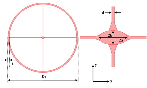
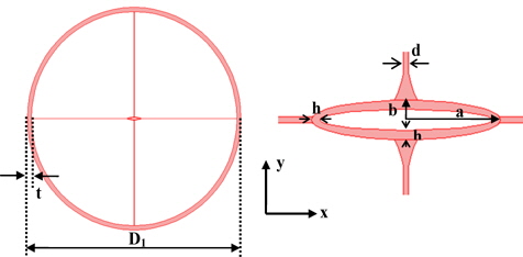
Recently, some suspended core THz fibers are reported, which aim to provide low-loss THz guidance [11, 12]. Considering the potential applications of a high birefringent THz waveguide, a suspended elliptical core THz fiber which incorporates an elliptical core suspended inside a large porous outer cladding is proposed in the paper. The whole cross-section of such THz fiber is shown in Fig. 1. The major and minor axes of the suspended elliptical core are 2a and 2b, and the thickness of four long supporting struts is d. The diameter of the fiber is D1, and the thickness of the outer tube is t. The pink area in the cross section represents the polymer material and the remainder is air. Since the refractive indexes of most polymer materials for THz guiding are around 1.5 in the frequency region of interest[13], the refractive index of the polymer material and the surrounding air is assumed to be n1=1.5 and n0=1, to simplify analysis.
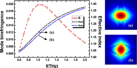
A full-vector FEM [14] with the perfectly matched layer (PML) boundary conditions is used to get modal effective indexes (neff). The mode birefringence is the difference in the real part of neff for the two polarizations, that is B=neffx-neffy. In our discussion, only the two fundamental orthogonal polarization modes (namely, the x-polarized mode and the y-polarized mode) are investigated.
In the analysis, the parameters of the suspended elliptical core THz fiber are supposed to be a = 106 μm, b = 53 μm, d = 20 μm, D1 = 2.55 mm, t = 0.1 mm and ellipticity ρ = 0.5. Keeping the parameters unchanged, the mode birefringence versus frequency in a range of 0.6 to 2 THz is calculated. As shown in Fig. 2, there is an increasing functional relationship between the effective indices and frequency. The mode birefringence increases with frequency initially and reaches the maximum Bmax = 0.01981 at f = 1 THz. The corresponding time average power flow distributions of the x- and y-polarized modes at f = 1 THz are shown in insets (a) and (b), respectively. It can be seen that the x-polarized mode is better confined than the y-polarized mode. Although the design can provide good confinement for the x-polarized mode, large relative absorption loss will occur as well, which is evidently shown in Fig. 4. Furthermore, it is obvious that the THz fiber exhibits high mode birefringence on a level of 10-2 over a wide frequency range.
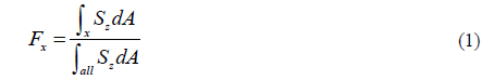
The power fractions of the mode power (F) in polymer material (region I) and porous cladding (region II) of the proposed suspended elliptical core THz fiber can be defined as:

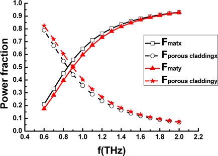
where Sz is the time average Poynting vector along the propagation direction (z axis), the subscript x={I, II} represents each region, ‘all’ refers to the integral over the whole cross section. Figure 3 shows the fraction of power with respect to frequency for the two regions. It can be seen that for both x- and y-polarized modes, when f increases, the power fraction in the polymer material region is increasing, but decreasing in the porous cladding. It means that less power will leak to the porous cladding and the leaky loss of waveguide becomes lower as f increases. Moreover, we can see that the x-polarized mode is better confined in the suspended elliptical core than that of y-polarized mode when the major axis lies in the x-direction, and vice versa. In another word, the leaky loss is low and the y-polarized mode experiences much less loss caused by material absorption, which is also shown in Fig. 4 for clarity.
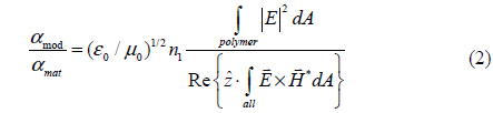
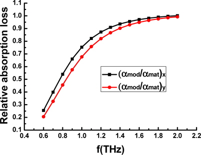
To investigate the modal absorption loss of the waveguide, as a result of material absorption, we calculate the following relative absorption loss for the fundamental modes of the proposed suspended elliptical core THz fiber [15]:

Where αmod and αmat are the absorption coefficients of the fundamental polarization modes and the bulk material (polymer), respectively. ε0 and μ0 are the permittivity and permeability of free space, respectively. and are respectively the electric and magnetic fields. As Fig. 4 shows the relative absorption loss of the x-polarized mode is larger than for the y-polarized mode and the difference between them became smaller when f increased. It can be explained that the x-polarized mode has larger power fraction in polymer material than that of the y-polarized mode(see Fig. 3), so it experiences more material absorption. Furthermore, most mode power will be confined in the suspended elliptical core with larger f for both x- and y-polarized modes, so the difference of relative absorption loss between them is subtle in the high frequency region.
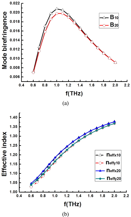
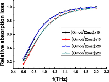
In order to optimize our design, the influences of d and ρ on fiber mode birefringence, the effective indices and relative absorption loss are discussed in the following steps. First, the values of a = 106 μm, b = 53 μm, D1 = 2.55 mm, t = 0.1 mm and ellipticity ρ = 0.5 are fixed, while the size of d becomes 10 μm. The calculated results show that the larger thickness (d) of the supporting strut will result in larger effective indices as shown in Fig. 5(b). This can be understood due to the fact that the larger d ensures more mode power distributed in the polymer material, which essentially contributes to the larger relative absorption loss as shown in Fig. 6. However, as a large part of mode power is confined in suspended elliptical core in the high frequency region, the difference between them is not obvious. As shown in Fig. 5(a), the maximum of mode birefringence increases from 0.01981(d = 20 μm,f = 1 THz) to 0.02081(d = 10 μm, f = 1 THz). It means that the mode birefringence increases with decreasing d.
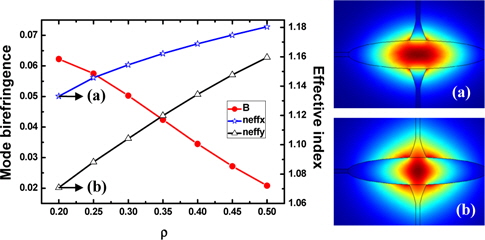
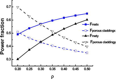
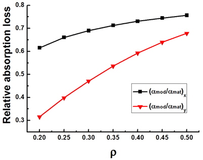
Secondly, the values of d = 10 μm, D1 = 2.55 mm, t = 0.1 mm, f =1 THz and elliptical core area S ( S =π ab =π * 106 μm*53 μm) are fixed, while the size of ellipticity ρ is different. Figure 7 illustrates that the mode birefringence decreases with ρ while the effective indices of x- and y-polarized modes are both increasing, and an extremely large mode birefringence(≈0.06226) is obtained when ellipticity is 0.2. The corresponding time average power flow distributions of the x- and y-polarized modes at ρ = 0.2 are shown in insets (a) and (b), respectively. It means that the asymmetry of elliptical core can be enhanced by decreasing the ellipticity ρ. Moreover, when ρ increases, more mode power will be distributed in polymer material (as shown in Fig. 8), which means higher material absorption loss. It is consistent with Fig. 9, and the relative absorption loss increases with ρ. Thus, one can conclude that smaller d and ρ permit high mode birefringence to be easily realized on suspended elliptical core THz fiber.
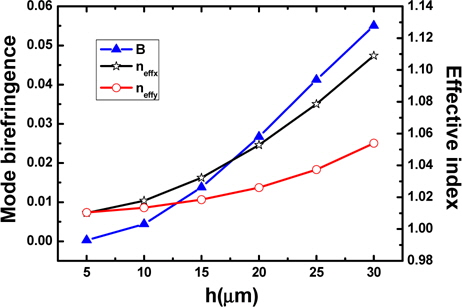
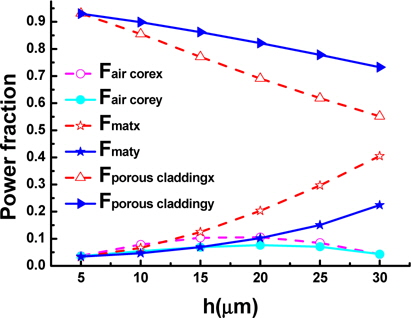
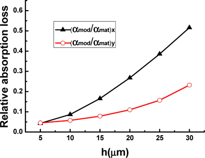
Finally, considering almost all materials are highly absorbent in THz region and dry air is the most transparent transmission medium for THz wave, a suspended hollow elliptical core fiber(as shown in Fig. 10) is also discussed in the paper. As mentioned above, a high mode birefringence (≈0.06226) is obtained when ellipticity is 0.2 (a = 167.6 μm, b = 33.52 μm, d = 10 μm, D1 = 2.55 mm, t = 0.1 mm, ρ = 0.2 and f = 1 THz). Keeping the parameters unchanged, the thickness (h) of the elliptical ring is varied. Figure 11 shows that the effective indices for both polarizations increase with h. The mode birefringence increases from 0.000278 to 0.055046 when h changes from 5 μm to 30 μm, which indicates that it is easier to achieve high mode birefringence for elliptical ring with large thickness. It can be explained that for both x- and y-polarized modes, when h increases, more THz wave will propagate in the air core and the elliptical ring (as shown in Fig. 12) and the effect of the asymmetric core becomes apparent. The power fractions of the two polarizations in different parts are shown in Fig. 12, which will affect the effective index, the mode birefringence, and the relative absorption loss of the THz fibers. Obviously, the mode power in porous cladding decreases with h, and the power fraction of x-polarized mode in polymer material is higher than y-polarized mode. In another word, the leaky loss is low and the y-polarized mode experiences much less loss caused by material absorption, which is also shown in Fig. 13 for clarity. Furthermore, the relative absorption for both x- and y-polarized modes increase with h (as shown in Fig. 13), which is consistent with Fig. 12. Compared with Fig. 11, we find that high mode birefringence and low relative absorption loss cannot coexist in such a kind of fiber.
In the paper, a novel high birefringent polymer THz fiber with a suspended elliptical core is proposed Dependence study of mode birefringence on thickness of the supporting strut and ellipticity, the power distribution of mode power and the relative absorption loss are investigated with a full-vector FEM. Simulation results show that the suspended elliptical fiber exhibits high mode birefringence on a level of 10-2 over a wide frequency range. The decrease of d and ρ is helpful to enhance mode birefringence, and a high mode birefringence (≈0.06226) is obtained when ellipticity is 0.2. Compared with other birefrigent THz fiber[16-18], the mode birefringence is extremely large. A suspended hollow elliptical core fiber is also investigated, which proves that smaller air core is easy to achieve high mode birefringence but endures high loss caused by polymer material absorption. Moreover, the proposal for the THz fibers based on a suspended elliptical core structure indicates a method to achieve unique property for THz fibers with complex cross section.
Finally, we note that the fabrication of such THz fiber designs could be realized by several methods, such as a capillary stacking technique, a polymer casting technique, a hole drilling technique, a combination of drilling and stacking, and so on[11,19].