Various methods can be used to create a stereoscopic image, and the most common of these methods acquires multiple images from stereo and multi-view cameras to create a three-dimensional (3D) image. Recently, depth images have been widely used to generate images at the desired viewpoints, which are then used to create a 3D image. In addition, 3D images have been generated from multiple texture and depth images. This widespread use of depth and texture images has led to extensive studies on their encoding. Digital information, such as that used in images, has the advantage of being easy to transfer and store; however, it has the disadvantage of being easily copied and modified. Therefore, to effectively protect the copyright and prevent illegal copying, counterfeiting, or modification, several studies on digital watermarking have been conducted even for 3D images that use depth and texture images [1].
Advancements in the watermarking technology have ensured that its application has gradually moved from the spatial domain to the frequency domain. In comparison with the spatial-domain watermarking technology, the frequencydomain watermarking technology is more robust to attacks, although the frequency characteristics do not allow the exact selection of the watermarking embedment location. In the case of frequency-domain watermarking, the watermark is embedded by changing the frequency coefficient. Ruanaidh [2] proposed a water-marking method in which watermarks are embedded in the phases using discrete Fourier transform (DFT), and Cox et al. [3] and Barni et al. [4] proposed a method in which the critical frequency coefficients are selected using discrete cosine transform (DCT), and in which watermarks are embedded in the order of the magnitudes of these coefficients.
The prevalence of stereoscopic images has led to studies on the protection of stereo images, and studies related to the topic of this paper are briefly discussed here. After carrying out a dual-tree complex wavelet transform (DT-CWT), Lee selected coefficients considering depth-image-based rendering (DIBR) characteristics and quantized them for watermarking. Wang et al. [5] selected a region that was nearly unaffected by various attacks from a scale-invariant feature transform (SIFT), carried out DCT on this region, and then embedded a watermark by applying the spread spectrum technique to the coefficients. In addition, Lin and Wu [6] proposed a technique in which the part correspondding to the front view is selected using depth information, as this prevents damage to the watermark embedded in the image of the arbitrary viewpoint produced by DIBR; the watermark is embedded by extracting the information corresponding to the objects in the selected part. Seo et al. [7] proposed a watermarking method that protects the copyright of a 3D image generated from depth and texture images by using 3D warping. Furthermore, in [8], a midviewpoint image generated by 3D warping at an arbitrary position was returned to the original view-point by finding the moving distance of the viewpoint. A watermark detection method implemented at the original time is presented.
The rest of this paper is organized as follows: Section II describes 3D warping; Section III discusses the watermarking method; Section IV presents the test results; and Section V presents the conclusions.
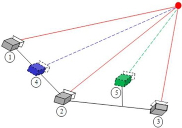
To generate an image of a virtual viewpoint on the basis of the geometric configuration of a camera, information pertaining to the depth of an image and the intrinsic and extrinsic parameters of the camera are used to calculate the actual 3D coordinates of the image. In addition, in virtual cameras, the calculated 3D coordinates are projected onto the location.
The geometric configuration of the camera is used to capture an image, and this is shown using the pinhole camera model in Fig. 1. The image captured by a pinhole camera appears as an inverse image at the –f location on the Z axis. In this case, however, it is difficult to interpret the image in 3D coordinates; therefore, the image plane needs to be moved by the camera’s focal distance f on the Z axis before it is interpreted.
The relationship of the actual projection of an object in a 3D coordinate system onto an image plane can be analyzed using the trigonometric proportion method, as shown in Fig. 1, and is represented as Eq. (1):

where x and y denote the 2D coordinates of the object projected onto the image plane,

X, Y, and Z denote the 3D coordinates of the projected object. In general, a depth image shows an object’s depth as a converted value between 0 and 255. To generate a virtual viewpoint image, the actual 3D co-ordinates, X, Y, and Z of the image are required, and Z can be obtained using Eq. (3) as follows:

where Z(
To obtain the actual 3D coordinates of an image, the inverse matrix of


If Eqs. (6) and (7) are rearranged for X and Y, we can obtain Eqs. (8) and (9) as follows:


To project an image from a virtual viewpoint, the virtual viewpoint of the camera must first be defined, and the image of the actual reference viewpoint is then projected onto the location of the virtual viewpoint of the camera by using the actual 3D coordinates, X, Y, and Z, of the image, obtained from Eqs. (8) and (9), and the intrinsic and extrinsic parameters of the camera.
This study proposes two techniques and investigates the robustness of digital watermarking techniques for middle viewpoint images generated using 3D warping. In the first technique, watermarking is carried out by discrete wavelet transform (DWT) on the region that survived maximum warping; in the second technique, watermarking is carried out after conducting DWT on a local region with the smallest area of disocclusion, which was found using a search of the region that survived maximum warping.
>
A. DWT on Entire Overlapping Region
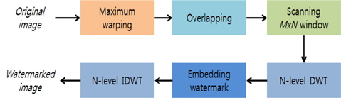
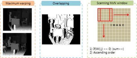
The first method is shown in Fig. 2. To begin with, a given depth image is used for 3D warping in both the right and the left direction. Theoretically, the maximum range of 3D warping is infinite, but it is generally limited to the range in which stereo and multi-view images remain as valid images. Although this maximum range can be set subjectively, there is sufficient general agreement on the range of 3D warping so that dimensionality is maintained. Warping at the maximum range will produce two images (right and left stereo images). These two images are then overlapped to find their common region, which corresponds to the upper-right image of Fig. 3. This common region does not include dis-occlusion regions, irrespective of the extent of 3D warping required to make the stereo and multi-view images. In a watermarked disocclusion region (a region that can be removed by 3D warping), the water-mark will naturally disappear during normal image processing when producing stereo and multi-view images by using depth and texture images. Therefore, to maximize the survival of a watermark during such image processing, it is necessary to find a common region that can survive 3D warping.
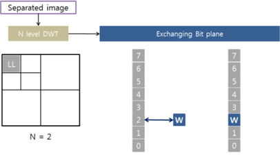
When the overlapping region is obtained, DWT is performed and a watermark is embedded in the LL region by using the bit substitution method. In this paper, the watermark is embedded using a relatively simple method to determine the effect of 3D warping on watermarking.
Replacing a specific bit plane with a watermark bit is equivalent to adding or subtracting a fixed value to a DWT coefficient. Table 1 shows the watermarking characteristics according to the level of DWT used. 3D warping entails moving to the right by a distance of 6.43 cm. The experimental results presented in Table 1 confirm the recovery of the watermark after a blurring attack according to the DWT level. Superior characteristics are shown at Level 3; therefore, in this study, watermarking was carried out at Level 3 of DWT.
[Table 1.] Watermarking characteristics according to DWT level
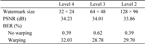
Watermarking characteristics according to DWT level
>
B. Searching the Overlapping Region to Select a Region
It is known that the overlapping region that is watermarked by using the first method includes some areas of disocclusion. Therefore, to minimize these regions of disocclusion, it is first necessary to search the overlapping region for such areas of disocclusion. A watermarking algorithm that includes this search process is shown in Fig. 3. The algorithm identifies the overlapping region by using register scanning to find regions with a small amount of disocclusion. DWT is then performed for the searched regions, and the watermark is embedded in the DWT coefficient. Lastly, inverse DWT is carried out to obtain an embedded watermark image.
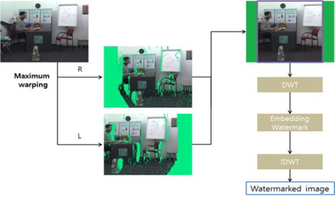
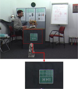
Fig. 4 shows the schematic for the second water-marking method. A stereo image is produced after performing left and right 3D warping at maximum. An overlapping image is then created by obtaining a common region (that was not removed by warping) by using the stereo image but without performing a hole-filling action.
Lastly, blocks that have regions with smaller amounts of dis-occlusion are found by performing a scanning action. These blocks are arranged in order and are watermarked according to the number of watermarks. As in the first algorithm, watermarks are embedded using the LL sub-band bit exchange method after conducting DWT.
>
C. Watermark Bit Embedding and Extraction
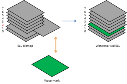
This section explains the bit exchange method of watermarking. As shown in Fig. 5, multiple sub-bands are generated when DWT is applied to an image. Among these sub-bands, a watermark is embedded in the LL sub-band that has the lowest frequency. Fig. 5 shows the bit exchange method used, in which an applicable bit plane value is exchanged with the watermark bit ‘W.’ The action that extends this to all bit planes is shown in Fig. 6, where the third bit plane is exchanged with a watermark bit plane. Bit plane exchange is easier to perform if the LL sub-band size after performing DWT is the same as the size of the watermark bit plane.
>
D. Watermark Extraction by Viewpoint Recovery
If the moved viewpoint of an image can be known, the extraction of the embedded watermark from this image will be considerably easy.
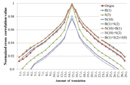
In the proposed extraction method, the correlation values between the reference image and the moved viewpoint image are calculated, and their trend is then used to find the viewpoint. Although many types of correlations exist, the normalized cross correlation (NCC) value is used here.
Fig. 7 shows the trend of NCC values when view-point movement and various types of attacks are applied. The amount of viewpoint movement is indicated on the x-axis, along with the NCC values of a multi-view image for an image in which the viewpoint was moved by 15Δ. Furthermore, B(1) represents a blurring attack at σ = 1; S(3), a sharpening attack at Level 3; N(10), a 10% salt-andpepper noise attack; and J(0), a JPEG quality 0 attack.
As shown in Fig. 7, the blurring attack and the salt-andpepper attack increase the NCC value, the sharpening attack reduces the NCC value, and the JPEG compression attack barely changes the NCC value. However, the NCC value is the largest at a certain viewpoint under any of these attacks; therefore, this viewpoint is considered the current viewpoint.
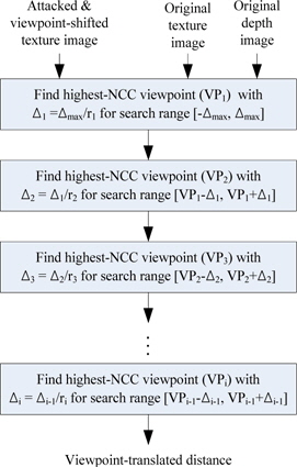
The viewpoint of an image moved to an arbitrary viewpoint cannot be found by an absolute calculation using a relative NCC value. Therefore, we propose the rough-tofine method, as shown by the schematic in Fig. 8.
As already mentioned, non-blind watermarking is assumed. Therefore, in addition to the moved viewpoint and the attacked images, the original reference view-point image and depth information are provided during watermark extraction. Furthermore, in this method, the maximum amount of movement in the left and the right direction is assumed (denoted as
The tracking method translates the reference image into various viewpoints by using the corresponding depth information, and finds the viewpoint of the highest NCC value for the translated image and the corresponding image. In this process, the amount of movement is first set as a large value, and the viewpoint is found by subdividing the viewpoint at which the NCC value is the highest. This process is then repeated to find the exact viewpoint.
This section presents the quantitative and visual test results for the proposed techniques described above.
>
A. Quantitative Test Results for the First Method
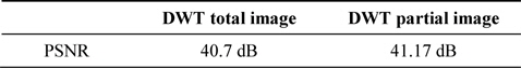
In the first method, the size of the overlapping region was 768 × 768 pixels, and Level 3 DWT was carried out. The watermark size was 48 × 48 pixels. The peak signal-to-noise ratio (PSNR) values of the watermarked image are given in Table 2. The total image represents the PSNR of the watermarked total image (measured as 40.7 dB), and the partial image represents the PSNR of the overlapping region (measured as 41.17 dB).
[Table 2.] PSNR value after watermarking
PSNR value after watermarking
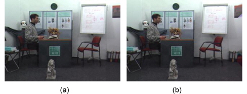
Fig. 9 shows the watermarked image (Fig. 9(a) shows the original image; and Fig. 9(b), the watermarked image). A comparison of these two images confirms almost no degradation of visual resolution by water-marking, and therefore, the invisibility required by the watermarking algorithm is considered to be satisfied.
[Fig. 9.] Result of embedding a watermark in an image: (a) original image and (b) watermarked image.

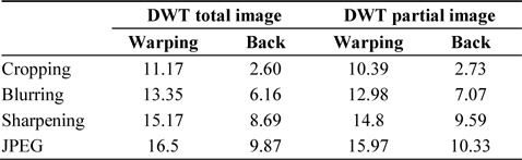
Table 3 shows the results of the robustness against attacks in terms of the bit error rate (BER) for both the total image and the partial image. Furthermore, for the two types of images, it also shows the experimental results of robustness when the watermark was extracted by restoring the image after finding the viewpoint, and when the watermark was extracted without restoring the image.
[Table 3.] Results obtained using the first method
Results obtained using the first method
Cropping, blurring, sharpening, and JPEG compression attacks were applied to all four types of images. The results show that the best BER was obtained in the case when the watermark was found after tracking the viewpoint, detecting the viewpoint, and then, restoring it to its original image location. The BER values for each type of attack were 2.60%, 6.16%, 8.69%, and 9.87%, respectively. In this experiment, 6.42-cm 3D warping and Gaussian blurring were carried out. The JPEG compression rate was 5 out of a compression rate range of 0–10.
>
B. Quantitative Results of the Second Method
This section provides the quantitative results obtained using the second technique. In this method, a block size of 256 × 192 pixels was used to find regions of fewer disocclusions, and Level 3 DWT was performed as in the preceding experiment. Therefore, the embedded watermark size was 32 × 24 pixels, which is the same size as that of the Level 3 LL sub-band. Furthermore, the fourth bit plane was exchanged with a watermark in the LL sub-band. Fig. 10 shows an example of a block selected for watermarking, where the PSNR of the watermarked image is 49.85 dB.
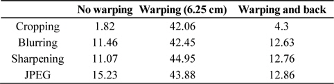
The BER values of the second method are provided in Table 4. As in the preceding experiment, the best BER was obtained after warping and restoring the viewpoint to its original viewpoint. However, although this method was predicted to have a higher robustness than the first method because it included fewer disocclusion regions, the BER of the first method was found to be higher.
[Table 4.] Results of the second method (BER)
Results of the second method (BER)
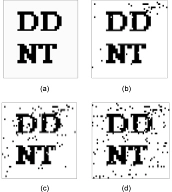
Fig. 11 shows the extracted watermarks according to BER, which are examples of the experimental results presented in Tables 3 and 4.
Because a copyright can be easily verified by checking the original watermark even when the BER decreases, the proposed algorithm can be used to watermark stereo and multi-view images generated from texture and depth images to protect their copyright.
Two watermarking techniques were proposed for stereo and multi-view images generated from texture and depth images. In the first method, a depth image is used to generate a stereo image with the largest viewpoint difference on the left and the right. The overlapping region in the stereo image that does not disappear after warping is then obtained, and DWT is applied to this region in order to embed a watermark in the LL sub-band. In the second method, where the effect of the disocclusion regions is reduced, the region with fewer disocclusion regions in the overlapping region is watermarked. The BER characteristics of these two techniques were found to be about 3% and 16%, respectively, for various attacks, and the characteristics of the original watermark were all visually confirmed. Therefore, we concluded that the proposed watermarking methods can be widely used for stereo and multi-view images generated from texture and depth images.