Flash memory uses non-movable elements for the execution of data access, fetch, and data retrieve operations. Non-volatile memory chips retain data even in the case of power loss. The form factor and capacity integrate a solidstate drive (SSD) into a mass storage device within a system rather than using it as a portable device because of a few of its complexities and limitations [1].
>
A. SSD and Premature Wear-Out Problem
Although they offer the advantages of faster access time, reduced noise, low power consumption, and high durability, SSDs are facing a major roadblock for growth in terms of their endurance period. The lifetime of a flash memory is defined in terms of the endurance period, which is dependent on the number of program and erase (P/E) cycles. NAND flash blocks typically have bit 1 stored in them, and every time they are programmed, they acquire bit 0. The floating transistor gate of the NAND flash loses its oxide layer with repeated erase operations. Further, on the basis of the statistical average calculated from industry implementations by memory design companies, we can approximate that single-level cells become read-only after 100,000 P/E cycles, and multi-level cells, after 10,000 P/E cycles [2].
>
B. Causes of Wear: Write and Erase
For any data update, hard disk drives (HDD) provide an overwrite feature, but in the case of SSDs, this feature is not possible. Therefore, whenever a data request comes in, SSDs address this by performing functions, such as out-ofplace update, wear leveling, and garbage collection. Further, with every out-of-place update, the number of write operations performed increases, and this factor is known as Write Amplification. While a junk copy remains in the memory block, free space needs to be created for other memory operations. At this point, garbage collection is performed; this handles the function of tracking garbage or junk data and then, performing an erase operation.
The main obstacle in dealing with the write and erase procedure is that although program write and read can be done in terms of pages, the erase operation needs to be done in terms of blocks [3]. Therefore, for the case wherein there is a miniscule amount of data present in the memory and a memory write request comes in, many algorithms have been designed in such a way that they initiate an operation to erase the whole block from the initial stage, thus decreasing the endurance period and defeating the whole purpose of out-of-place update, wear leveling, and garbage collection.
>
C. Options for Improving Endurance
In this study, we attempt to decrease the write amplifycation concerned with an out-of-place update to a certain extent through efficient handling of write requests up to the threshold level, which results in an increased endurance period.
II. WEAR LEVELING AND FLASH MEMORY MANAGEMENT
Two basic wear leveling types, namely static wear leveling and dynamic wear leveling, have been followed [3]. The basic principle of any wear leveling algorithm includes the following: 1) taking advantage of hot and cold data, 2) placing hot and cold data, and 3) avoiding additional data migration.
In this study, hot data were frequently updated, and cold data remained idle for a considerable amount of time without any update.
Dynamic wear leveling allows a block to be repeatedly programmed and erased to its set limit and then, proceeds to use other blocks. However, this type of algorithm does not attempt to move cold data, and hence, some cold data may remain in a block without update, thereby leading to overutilization of some frequently used blocks and thus, in an uneven wear-out of blocks.
Static wear leveling involves moving cold data to the more worn-out blocks and hot data to the less worn-out blocks; thus, this algorithm tries to even out the number of erasures in a relatively efficient manner. However, there is a risk of increasing the endurance if additional data migration is not effectively handled, with added power loss.
The NAND flash controller manages a memory operation with the following three important policies: out-of-place update, wear leveling, and garbage collection. Typically, it handles the logical to physical block address translation. All these are termed to be part of the flash translation layer.
III. DIFFERENT STATIC WEAR LEVELING IMPLEMENTATION TECNIQUES
Three static wear leveling algorithms have been thoroughly researched for this project. They are as follows:
Like every wear leveling algorithm, the aim of the rejuvenator [4] is to even out the erase count of all the memory blocks so that no single memory block reaches its maximum erase count because if any one of the blocks reaches its maximum erase count, the entire memory will be out of use. The rejuvenator separates hot data and cold data and arranges them in order to wear them evenly [4]. Hot data identification is an integral part of the rejuvenator.
It has a window-based scheme to identify the hot data. At any point of time, the logical address with the highest counter value is considered hot.
The dual pool [5] algorithm is based on two key ideas: to cease the wearing of blocks by storing cold data and to smartly leave alone blocks until wear leveling takes effect.
This algorithm logically divides the logical block addressing (LBA) into two pools, namely hot pool and cold pool. When an address in the hot pool gets hotter or any address in the cold pool gets colder, it is moved to the other pool, thereby maintaining even erasure cycles. Two main processes that are included in the dual pool algorithm are cold-data migration and hot-cold migration. Cold data should be moved away from young blocks, and conversely, old blocks should start storing cold data [5].
This algorithm is an extended version of dual pool [5]. Apart from the hot and cold pools, it introduces another pool called the neutral pool. The neutral pool contains blocks that have an erase count of around the average erase cycle of the entire block array.
The fundamental principle of this algorithm is that whenever there is a swapping of data from the hot pool to the cold pool, it is performed through the neutral pool. The decision making of which address to put in which pool is taken depending on the addresses in the neutral pool [6].
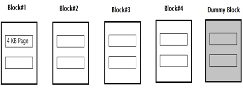
In this study, a miniature version of an industrial SSD is taken into consideration. A memory of 32 kB is considered, which is split into 4 blocks, each having two 4-kB pages. This is similar to the format of a practical NAND flash memory.
One dummy block is kept as overprovisioning, which is used while transferring or switching data between two blocks. This extra block seems to be an overhead since the memory under consideration is very small. For bigger memory, this block costs a very low percentage of the whole memory. The overhead may manifest in term of space, but it makes data migration significant.
A schematic representation of a memory used for testing in this study is shown in the Fig. 2.
As mentioned above, the premature wearing of the memory is due to the spatial locality of the workloads. The workload here refers to the write requests coming in to the memory. This algorithm takes into consideration only the write requests. The reason for this assumption is that only write requests cause the rewriting of data inside the memory. Serving a read request involves a simple pointing out of the address for which the read request has been encountered. Hence, the focus of the proposed algorithm is to uniformly distribute the write requests coming in, to a concentrated part of the memory.
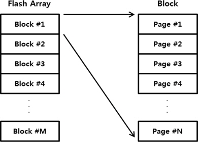
The stimuli of the proposed algorithm are as follows: 1) a specified address and 2) data to be written at this address. When a write request is encountered, a series of actions is triggered. Every write request comes with 8-bit data and 25- bit address. According to the mapping table, a physical address is directed for the particular data. There is a blockwise mapping of write operations.
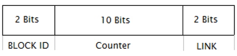
A counter is allotted to every block. The counter has a very specific structure wherein the two most significant bits (MSBs) are called Block ID and the two least significant bits (LSBs) are called LINK. The middle ten bits show the actual count value and are incremented with each write request served (Fig. 3). A saturation level is set (and can be modified) for every counter corresponding to the number of write operations within that block. Whenever this saturation level is sensed for a block, all the future write requests coming to it will be diverted to some other fresh block, which has a lower counter value implying a less-used block.
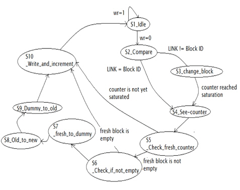
The design was implemented in Verilog code in the statemachine format. There are 10 states carrying out different tasks (Fig. 4).
Throughout write processing, a register is used as an indicator whenever a write request is being processed and the read operations are kept at bay when a particular write request is being processed.
The simulation results obtained in this study are in terms of the number of write operations that the memory can handle. Table 1 shown below keeps a record of the number of write requests accepted by the memory with and without the proposed algorithm.
[Table 1.] Analytical comparison
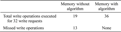
Analytical comparison
The simulation results presented below are obtained using the proposed algorithm with 36 write requests, of which 34 were concentrated to only two blocks as shown below. The saturation level set for every block is 16 write operations. The same test bench is run through both the memories with and without the proposed algorithm. It can be observed that the number of write requests served significantly changes upon the implementation of the algorithm.
Different test benches give different values for the maximum number of write operations executed. This variation is due to the spatial locality of the write requests. The more concentrated the write requests are, the smaller is the number of write operations that it can handle before reaching the saturation set for it.
The proposed design has been tested for various cases; in the following paragraphs, we discuss four of these different cases that the design has handled.
Case 1: The proposed design is checked for handling all the available blocks with a write request for each block.
Case 2: Write requests are sent to a single block till its threshold is reached in order to observe how the design behaves.
Case 3: One block is filled completely, and all the other blocks are filled one short of the threshold.
Case 4: The proposed design is checked for data handling by using a dummy block.
It can be analytically concluded that the increase in the endurance of the memory is related to the saturation level set for each block and the number of blocks in the memory. If S is saturation level set for each block and B is number of blocks, then the maximum number of write requests handled by the memory that are concentrated for a single block without the proposed algorithm is S, whereas the number of write requests handled by the memory with the proposed algorithm is S × B.
One of the major contributions of this study is decreasing the additional overheads due to the data migration. Again, following this algorithm, the number of data swaps between the blocks, which adds to the overhead, is directly related to the saturation level set for each block. The relative dependence of the number of block data swaps and the saturation level set are discussed in the next section.
In this study, the issue of wear leveling faced in the case of the SSD controller design has been addressed with respect to write request handling based on the static rejuvenator algorithm [4]. Memory blocks have been simplified as a two-dimensional array, and the data are written into it; further, the concept of a write-protected memory block has been implemented and analyzed along with different counters that act as flags to simulate different conditions.
The main feature of the proposed algorithm is to delay out-of-place updates till the threshold is reached, resulting in a low overhead. In addition, it increases endurance by a factor of the threshold level multiplied by the number of blocks in the memory.