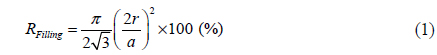
Optical films based on the microlens array (MLA) technology are widely used for brightness enhancement in illumination systems [1]. For example, backlights for liquid crystal displays usually adopt one or two MLA films, in addition to prism films and/or a reflective polarizer, to achieve low power consumption [2-3]. In general, MLA films consist of randomly positioned hemispherical lenses, the filling factor of which is in the range of 65-70%. The luminance gain of the MLA film is greater than that of a light diffuser film, but less than that of a one-dimensional prism film. The filling factor is defined as the ratio of the projection area of the lenses to the entire surface area of the film. A schematic structure of a conventional MLA film is shown in Table 1 (denoted as “conventional type”). Hemispherical microtextures 50-60 μm in diameter are randomly arranged with a filling factor of 65-70% on the MLA film of this type. It is known that the brightnessenhancement performance of an MLA film can be enhanced by increasing the filling factor of its microlenses [4, 5].
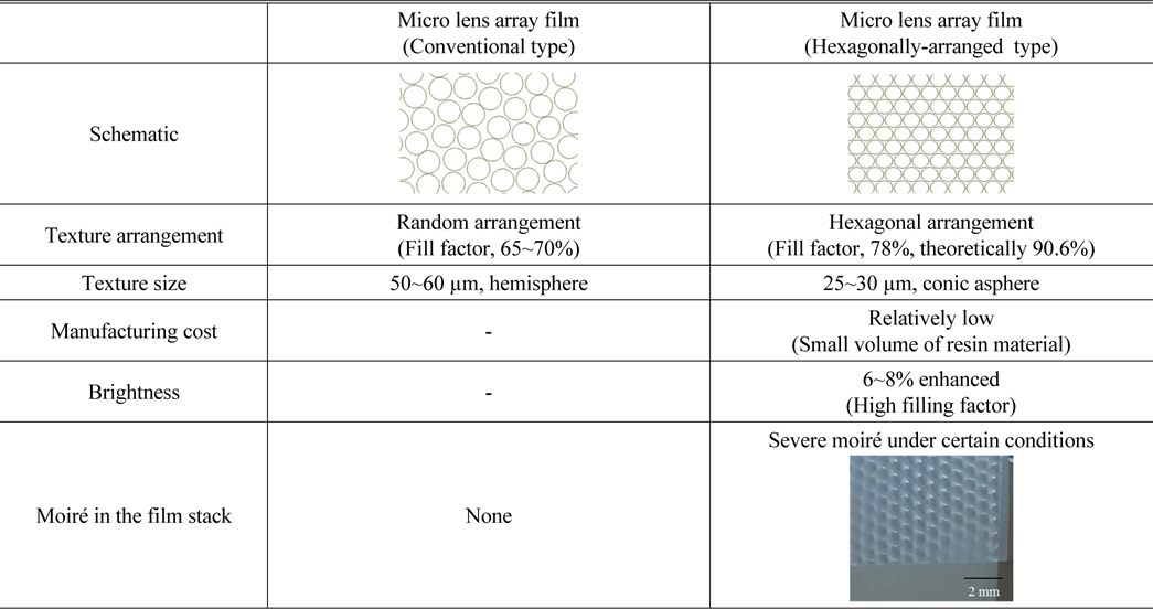
Comparison of two microlens array structures: conventional randomly-arranged type versus hexagonally-arranged type
Recently, optical films based on a hexagonally-arranged microlens array (HA-MLA) have attracted great attention because of their high potential for achieving better brightness-enhancement capability and lower production cost compared to conventional MLA films [6]. As compared in Table 1, the filling factor of the HA-MLA is around 70-80%, which is higher than that of the conventional film. The upper limit of the filling factor
In addition, the hemispherical lens can be switched to an aspheric lens, which can be optimized for better brightnessenhancement capability [7, 8]. It is known that adopting one HA-MLA film in a backlight improves the on-axis brightness by approximately 8-10%, compared to a conventional MLA film. Also, low production cost can be realized, because the amount of resin used in the manufacturing process can be reduced by decreasing lens diameter to 25-30 μm. However, an HA-MLA may bring about moiré problems in a doubleor multiple-layer stack, due to the periodic modulation of the microlenses on the film substrate. The moiré phenomenon degrades the picture quality of a display and thus should be avoided in such applications. Much effort has been spent to analyze and reduce moiré phenomena [1, 9, 10]. One approach toward a moiré-free platform is to randomize the periodic microstructures to some degree [11].
In this respect, it is necessary to optimize the optical structure of an MLA film to remove or reduce the moiré phenomenon in an optical device such as a backlight. Usually 1-3 MLA films are adopted in a backlight, and a moiré pattern may be formed when the number of the MLA films is at least two. In this study, several approaches for avoiding moirés between two HA-MLA films were investigated by optical simulation based on the ray-tracing technique [12]. In general, moiré formation between the MLA and the LCD pixel array is regarded as a more serious problem in LCD. Although the interference effect between the MLA and the LCD pixel array is not discussed in detail in this study, we do suggest a possibility for reducing this problem based on our approach.
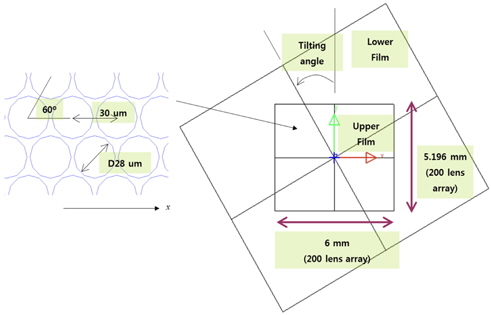
Figure 1 shows the schematic view of the MLA geometry adopted in the present moiré simulation. This model consists of two MLA films, the upper and the lower. The distance between upper and lower films was 0.15 mm, which was determined by considering the thickness of the base film (usually 0.125 mm) and the height of the MLA (10-30 µm). Circular holes with a diameter of 28 µm were hexagonally-arranged on the upper film at a pitch of 30 µm along the χ direction. The dimension of the upper film was 6.000× 5.196 mm2, on which 200× 200 holes were arranged. The moiré fringe is recognized generally when the moiré period is larger than 0.5 mm. Therefore, the present observation area of 6.000 × 5.196 mm2 seems large enough for scrutinizing the moiré problem. The lower film was placed beneath the upper film. The area of the lower film was 12.0× 10.2 mm2, and it was tilted with respect to the upper film by a certain angle. The hole texture of the lower film was prepared according to four possible approaches to reducing the moiré pattern, while the hole arrangement of the upper film was fixed. The four simulation conditions are summarized in Table 2.
[TABLE 2.] Simulation conditions: four possible approaches for avoiding moires
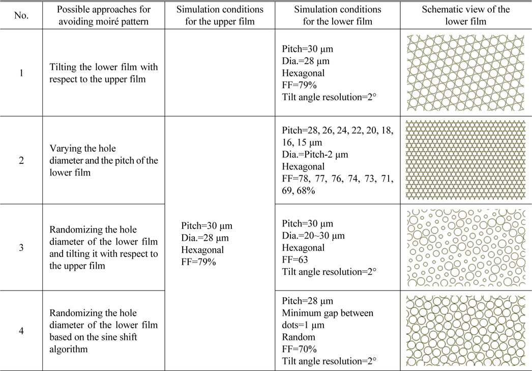
Simulation conditions: four possible approaches for avoiding moires
The first approach adopts the same hexagonally-arranged hole texture as that of the upper film, and only the relative orientation was changed systematically, i.e. the lower film was tilted with respect to the upper film at a step of 2°. In the second approach the pitch between the holes of the lower film was changed from 15 µm to 28 µm. The diameter of each hole was set to be smaller than the pitch by 2 µm, so that the fill factor was varied from 68 to 78%. The third approach was to randomize the hole size of the lower film in the range of 20-30 µm in diameter, and to tile the film with respect to the upper film. Finally, in the fourth approach the hole size was fixed to be 28 µm and the holes were randomly arranged using the sine shift algorithm [13].
During the simulation collimated light rays were incident upon the film stack from the bottom side of the lower film, and the transmitted rays were gathered by a receiver located at the top of the upper film. The resolution of the receiver (i.e. the mesh size) was 3.00×2.58 µm2. The transmittance of the holes was set to be 100% and the surface other than the holes absorbed the incident light completely. Commercially available software (LightTools, ORA Co.) was used as the ray-tracing simulator.
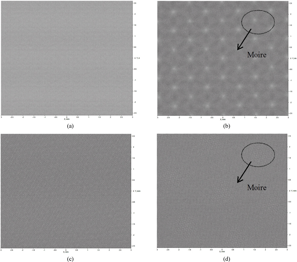
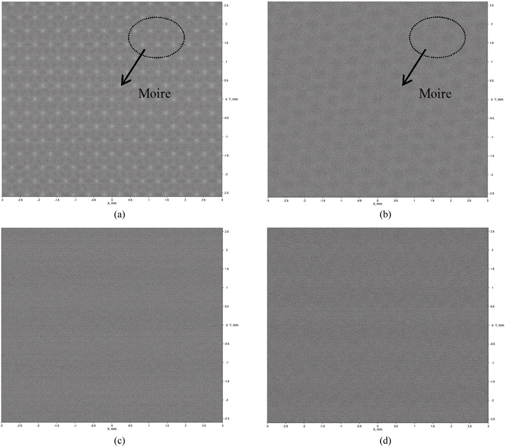
Figure 2 shows the simulation results for the first approach (denoted as “approach 1” in Table 2), where two films with the same hole texture were tilted relative to each other at a certain angle. Fig. 2(a) shows that there is no moiré fringe when the tilt angle of the lower film is 0°, which means the moiré period is infinite. However, as Fig. 2(b) shows, severe moiré fringes occur even at a very small tilt angle such as 2°, due to the long period of the moiré. The moiré pattern becomes weaker as the tilt angle increases, until an angle of ~24°, where the moiré fringes are almost invisible. Upon further increasing the tilt angle beyond 24° the moiré pattern becomes stronger, and then it finally disappears again at an angle of 60°. Since the hexagonal arrangement repeats every 60°, the moiré pattern also disappears at every 60°, when the hole arrangements of both films match. However, these angles cannot be optimal, because the allowable tolerance of the tilt angle is very small. Instead, the tilt angle of 24° is favorable, from the view point of tolerance. However, another moiré pattern might form due to interference between the MLA film and the LCD pixels, because the periodic arrangement of the microlenses still remains. Overall, this first approach is not a good solution to the moiré problem, because severe moiré fringes are formed in the vicinity of zero tilt angle, around which the period of the moiré fringe is very large.
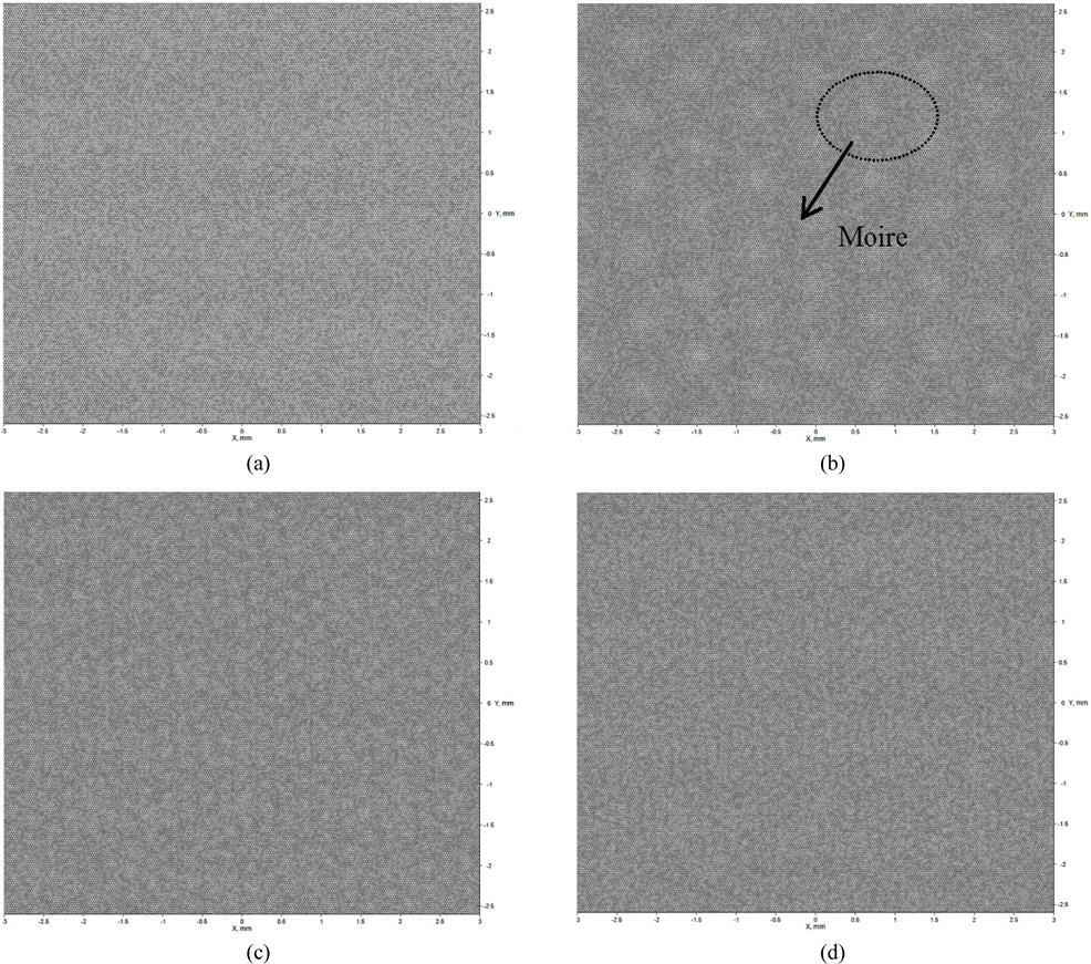
Figure 3 shows the simulation results for the second approach, where the pitch of the holes of the lower film was adjusted between 15 and 28 µm. The hole diameter was set to be smaller than the pitch by 2 µm for all cases. This approach is worth trying because the pitch mismatch between the two films is expected to be favorable for reducing moiré fringes. Figure 3 clearly shows that the moiré fringes become weaker as the pitch decreases, and that the moiré pattern is negligible at small pitches of 20 and 15 µm. However, the filling ratio decreases as the pitch increases, and the filling ratio of the film with a pitch of 15 µm is only 69%. This value is similar to that of a conventional MLA film (usually 65-70%). The filling ratio increases to 73% at a pitch of 20 µm, which is a little bit larger than the value for a conventional MLA film. It is thus expected that, compared to a conventional MLA film, the brightness of a backlight can be improved by adopting a hole pitch of 20 µm. However, there is still some possible formation of moiré fringes due to the interference effect between the periodic microlenses on the MLA film and the LCD pixels.
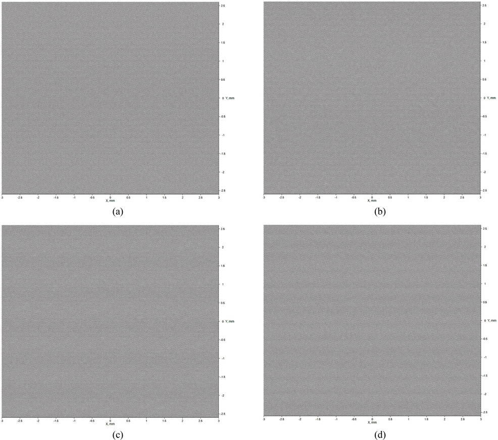
Figure 4 shows the simulation results for the schematic of the third approach shown in Table 2, where the hole diameter was randomly adjusted in the range of 20-30 µm. The average diameter was 25 µm. Centers of holes were arranged in a hexagonal lattice, and the tilting angle was changed by steps of 2°. This approach was aimed at investigating whether the degree of the moiré fringes shown in Fig. 2 could be reduced by randomizing the hole size. Figure 4 shows that although the overall moiré visibility becomes weaker in this approach, one can still detect moiré fringes under most simulation conditions. The fringes become weaker at a tilting angle of 10°. The most serious drawback of this approach is that the filling ratio is only 63%, due to the decrease in the average area of holes, which is even smaller than the filling ratio of a conventional MLA film.
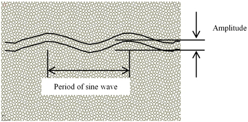
Figure 5 shows the simulation result for the last approach, where the hole position was randomly arranged while its diameter was fixed to be 28 µm. The randomization of the hole position was carried out using the sine shift algorithm, which is schematically shown in Fig. 6 [13]. According to this algorithm, the amplitude and the period of the sine modulation are adjusted to randomize the holes while keeping the filling ratio at a high value. This sinusoidal modulation was added along both
Finally, we would like to discuss the effect of the condition of the incident light on moiré formation. In practical cases, diffuse light is incident on the films, rather than collimated light. We carried out an additional moiré simulation based on diffuse light, which was generated using the Gaussian scattering model (diffusion angles of 0 and 5°). The results showed that the moiré pattern and its period are the same, irrespective of the diffuseness of the incident light. Only the moiré visibility shows some difference. We thus think that using collimated light in the simulation is an effective way to scrutinize the existence of the Moiré pattern due to MLA films.
Optical simulations were carried out for two stacked MLA films to find an optimized lens array for removing moiré fringes. The upper MLA film consisted of hexagonally-arranged circular holes, the filling factor of which was 79%. Four different lens configurations were adopted on the lower film and investigated by optical simulation. The first approach was to tilt the lower film with respect to the upper film while the same lens configuration was used in both films. The optimum tilt angle was found to be 24°, but we cannot exclude the possibility that an additional moiré pattern might be generated due to the interference between the periodic lens array of MLA films and the LCD pixels. The second approach was to change the hole diameter and pitch of the lower film, which showed that the moiré fringes were minimized at a pitch of 20 µm and diameter of 18 µm. In addition, the filling factor was 73%, which was larger than for a conventional MLA film, indicating that on-axis brightness would be enhanced. However, the interference between the MLA films and LCD pixels may not be completely removed, due to the periodic lens array on the MLA films. The third approach was to randomize the hole diameter in a certain range, which was found to be effective in reducing the moiré fringes under all conditions. However, the filling factor was very low, suggesting there is no advantage of this design over a conventional film, from the viewpoint of efficacy. The last approach was to randomize the lens positions while keeping the filling factor at a high value, above 70%. The holes were randomly arranged according to the sine shift algorithm, and it was found that the moiré fringes were effectively removed, thanks to the random configuration of the microlenses. The filling factor was 70% when the minimum distance between holes was 1 µm, and may be increased to 81% if this gap is set to zero. Moreover, an additional interference pattern between the MLA films and LCD pixels may not occur, thanks to the randomized configuration of microlenses. This study suggests that randomizing the lens configuration while keeping the filling factor high is an effective way to develop high-gain MLA films for backlight applications.